After Jim finished up some SEI checkouts and Mitch some ACB hardware swaps at WBSC10, Travis, Jason and I put the final touches on the pitch alignment. (Recall it was out of the pitch tol yesterday after we removed the First Contact sheet on the HR surface. The ISI is unlocked, and so is the ETMy and TMSy.
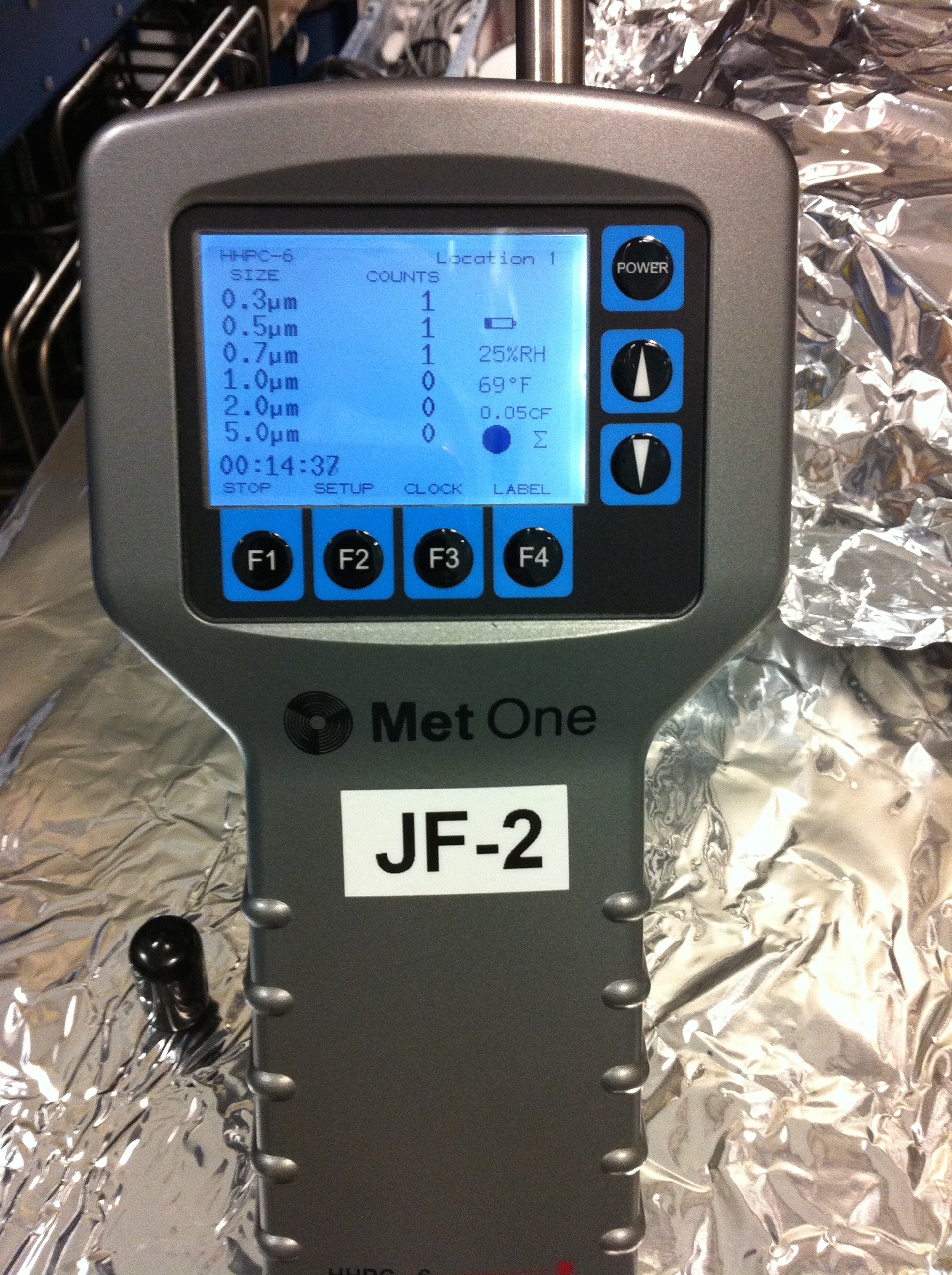
While in-chamber, we observed more particulate on places that we had previously cleaned. So, I took more PCL samples for Kate near the purge air port (to look for migration) and on a repeat place from a prior sample. For the most part, "we" have been cleaning the floor and large easy to get to surfaces in-chamber every day. I also went upstairs and clened the entire surface of the walking plates which have had little attention, hoping to limit what is getting stirred up and dumped in from above. I left a box of wipes there for SEI to keep up better mainenance there from now on. ;)
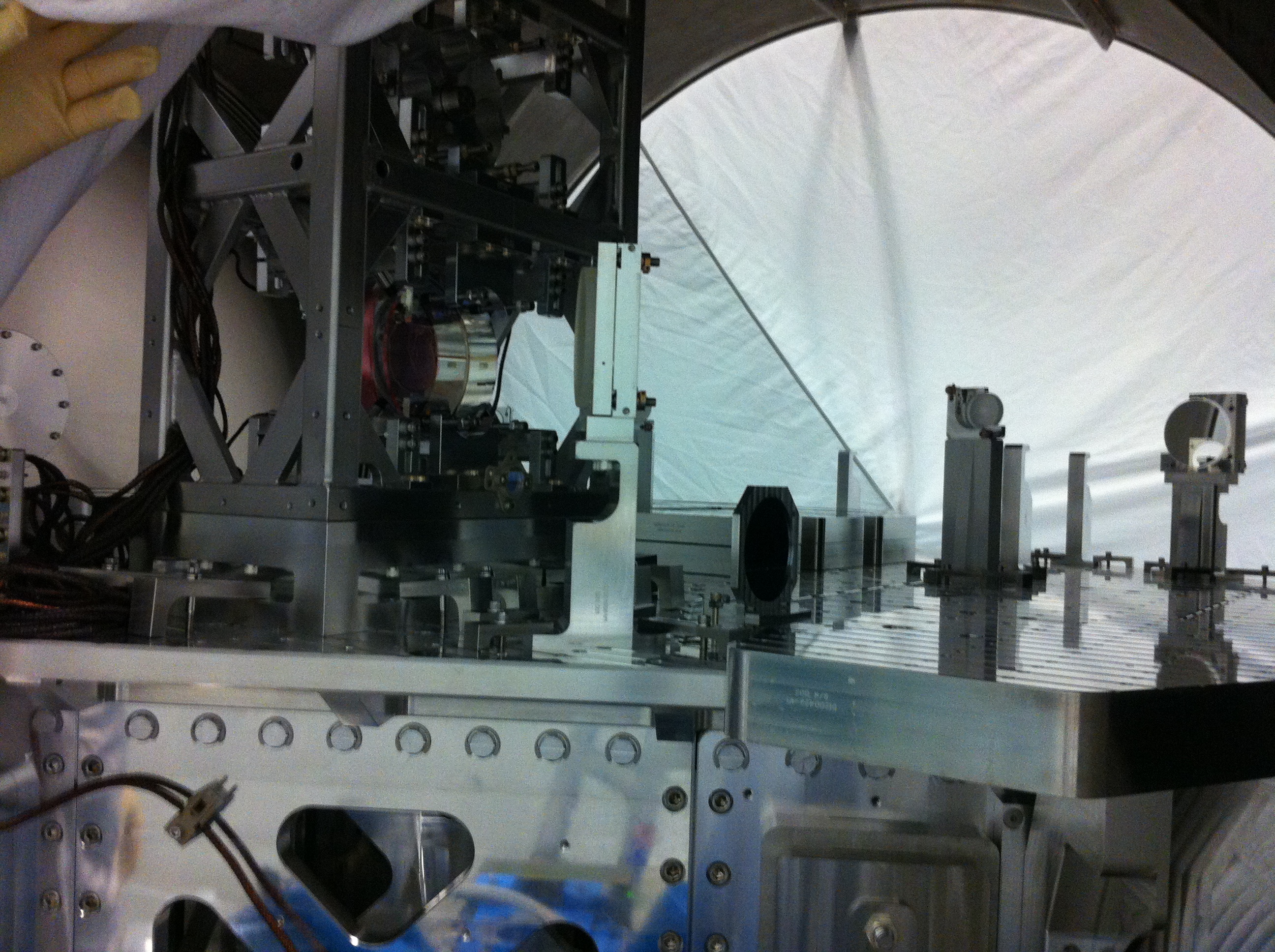
I left a witness plate and a 1" optic in the tube under the ACB (between the purge and the chamber optics) for Kate to do further studies on.
We'll keep hunting.

Note, the 1" optic serial number from the bag was: 1.0-FS-PL-1113