In addition to realigning the TMS, I also moved ETMX, ITMX, PR3, PR2 and IM4 tonight.
I initially aligned the straight shot to ISCT1 using TMS and the baffle diodes, then PR3 for the camera spot. Then I locked the cavity and tried engaging WFS. I was able to engage PIT DOF1 and YAW DOF 1, and although the error signals were eventually brought to zero, the cavity build up dropped compared to the hand alignment. The spot position also moved away from the spot on the camera that I had centered the single shot beam to. I tried engaging PIT DOF2, but the gain was set to 0, and has been for a few days. I tried a gain of 1, which was bad, and a gain of 0.1 which seemed to have no impact.
I gave up on the WFS and alinged the cavity by hand. By moving TMS in pitch I was able to get the cavity build up to 800 counts again, so I decided to abandon WFS for tonight and go on to locking COMM. The ALS_XARM guardian now has states for WFS.
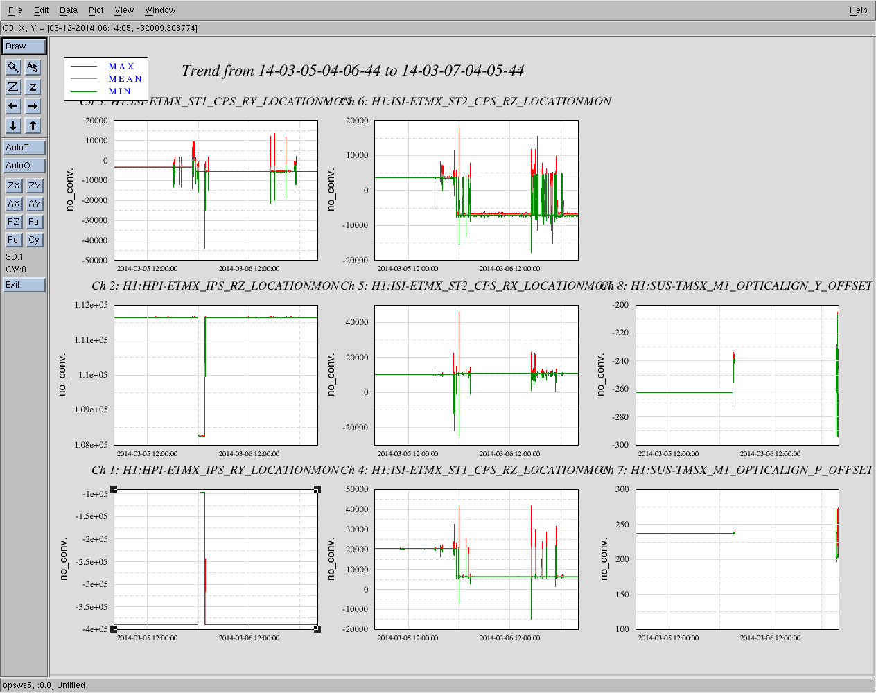
I was able to lock COMM using the guardian, and it was stable tonight with high gain ( I mean that the lock didn't drop unless I did something). The noise measured by the linearize error signal is a bit worse tonight, 200Hz. The first higher order modes were resonanting at the frequency were we though we had found the 00 mode last night. I found the 00 mode at -5990Hz, and tweaked up the alingment using IM4 and PR2.
Right now IM4 is at PIT -3077 YAW -5707 PR2 at 445 YAW at -383.1 I didn't save these using the IFO align screen in case the red team wants to restore their alignment from this morning using the current saved offsets.
I did save TMSX, ETMX, ITMX and PR3.

Jim and Travis connected all of the TMS cables to the in-vacuum feedthrus. This required completely rerouting 2 of the cables which were destined for feedthru's further away than where they were found mounted. None of them are screwed in. Although the ones that Corey mentions in the table above are missing hardware, they are a tight fit on the feedthru so I would advise just leaving them as is. The task of adding the screws to the connectors is too risky for the cable this late in the game. Adding the screws requires one to partially disassemble the cable which could cause a break inside of the connector.
And I enabled the damping and it's working.
However, it seems like LF coil is totally out, so TMSY might not be completely free.