Unassisted nominal ion pump current on-scale for the past three days -> OK
I have installed the latest PEM models into h1pemey, h1peml0 and h1pemmx. There were some naming errors and the MAG BLRMS channels which were mistakenly added have been removed. The DAQ was then restarted.
The DAC and ADC numbers for the simulink models of HAM2-HEPI and HAM3-HEPI were adjusted. Models are re-compiled and commited to the SVN.
The ground STS that will help evaluating SEI controls performance on the IMC was wired in these models (STS A). Its readouts initially looked like the sensor was railed. We re-cetered the sensor's test mass by pushing the centering button of its interface. Readouts make more sense now.
We measured a spectrum of the ground motion with this STS and compared it with the same measurement performed with the STS that is set on the ground at EY. Spectra have similar shape but different amplitude which make sense since the perturbation level is higher in the LVEA during work day (Friday, early afternoon), than it is at EY.
Folder arborscence was adjusted for HAM2-HEPI commissioning. HAM2-HEPI comissioning scripts were created from ETMY templates and added to these folder. Input filters and coordinate transform matrices are loaded. Same operations will be performed for HAM3-HEPI.
Why recentering the STS? It was centered already. Railing during the day is normal.
This ground STS is not railing now and has not been re-centered since last week. So, I would not say railing is the normal state of this sensor, even during the day.
This sensor does not rail at LLO.
Trends of the last 10 days. Last week was a 4-day week.
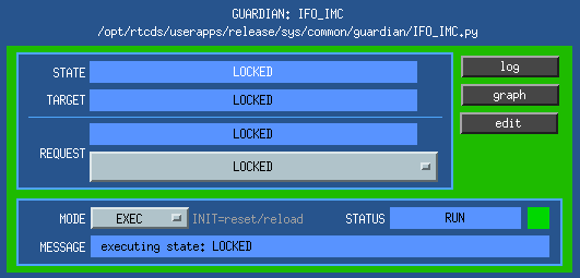
Yesteday, after the MC2 model was replaced, recompiled and burt restored to the settings of the preceeding night, we noticed a change of behaviour of the locking loop. It would no more lock easily with the usual settings, and with the higher gain settings it would trigger an oscillation at 21 Hz that we didn;t observe before. Today Matt worked at re-measuring the cross-over frequencies and re-tuning the filters and we'll write an entry about the changes he made and the new suggested operating settings.
In the meanwhile, I'm leaving the IMC locked for the weekend with mild gains, so to increase the chances of a spontaneous re-lock should an un-lock occour:
- common mode board: common gain at -5 db, compensation enabled, boost disabled, fast gain to -2 (as always)
- MC2: MC3_LOCK filters 5 and 8 engaged, gain to -1000; MC2_LOCK filters 2, 3 and 4 engaged, gain 0.03.
[Cheryl, Giacomo]
A couple of IMC activities were started today and not completed:
- the setup for the measurement of the cavity pole was prepared: using an SR785 signal analyzer, a swept sine is injected in the "inner loop transfer function input" on the PSL ISS front end on the field rack. The output of one of the ISS PD (A or B, we used the one that is not used int he loop in loop) is taken from the same field rack and sent to one of the channels. A Thorlabs PDA100A photodiode sits on the IOT1 table and is connected to the other channel fo the signal analyzer using one the the (unfortunately currently available) WFS RF cable. The PDA100A is put in the REFL path with the IMC both unlocked and misaligned to measure the relative TF of the two PD. Then it is moved to the TRANS path, the IMC locked, and the measurement repeated. The ratio of the two TF should give the IMC transfer fucntion. A quick measure was taken late this evening, but it still needs to be analyzied (and checked for errors).
- with the goal of computing a power budget, we checked if all the beams were coming out pretty much in the expected positions:
- the forawrd and backward beams were coming out from their (common) viewport pretty much in the expected positions (they pretty much covnerge at maybe 20 inches from the viewport).
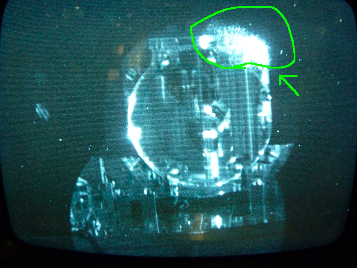
- the parking beam was not visible, and it seemed to be clipping on the baffle right in front of IM4.
- IM3 and IM4 also showed to have drifted during pumpdown in pitch and yaw, much more thean IM1 and IM2. Note that bringing them back to the "in-air" positions (as read by the OSEMs) did not make the parking beam reach its target, and apparently spoiled the position of the IM4 forward and backward transmitted beams (they were still coming out of the viewport, but convergin much farther away)
We played with the IM suspensions to try to reroute the parking beam to its intended location, but we started late due to other activities going on and we only got to the point in which the beam is badly clipped by the parking baffle (but at least is visible!). We are not far, but not quiete there yet. We'll resume next week.
Matt, Lisa With the fixed laser calibrator head we could finally make a measurement of the RF signal chain of the IMC LSC RFPD (24.078 MHz, S/N: S1203396). - Laser Head: 4 mW @ 980 nm; - Laser Head RF input calibration: 13e-3 W/V; - LSC RFPD DC Transimpedance = 200 Ohm; - LSC RFPD RF Transimpedance = 476 Ohm; Calibration using the DC response * Measured REFL_DC = 480 counts => Resp = 480/(1638 [counts/V] * 200 [V/A] * 4e-3 [W]) = 0.37 [A/W] RF Signal chain - RF input modulation to the Laser Head Calibrator: 0.1 Vptp sine @ 24.078473 MHz; => Expected RF to the demod board = 476 [V/A] x 0.37 [A/W] x 13e-3 [W/V] x 0.1 [Vptp] = 230 mVptp * Measured RF_in to the demod board: 240 mVptp => Expected I/Q monitor of the demod board = 10 (demod board gain) x 1/2 (mixer) x 240 [mV] = 1.2 Vptp @ 100 Hz * Measured I/Q monitors of the demod board: 1.3 Vptp * Measured TEST1 input of the common board: 1.3 Vptp The measured values are withing 10% of what we expected.
Mostly important only to me. Needed to move the DI mounting points on the North side to make room for the Pier Pod modules. This just means that I needed to record the before and after numbers cause they are no longer the same.
A few weeks ago, Vincent reported some of BSC2's St2 cps-es were "weird". With no changes to the system, some were reading ~ +/-15000 cts. Today, in preparation for fixing the system, Vincent and I checked the sensors again and they were back to normal. Grounding issues are suspected, and a better connection to ground was added this afternoon. Hopefully, the sensors are now fixed, but power spectra still show some noise in some of the sensors. Vincent will be taking TF's over the weekend, in preparation for the impending BS glass install.
The slow controls are working now for the IMC WFS whitening filters.
Kyle Removed bellows tie-rods from spool connecting BSC9 to BSC5 -> Started pumping X-end -> Noticed that BSC5 gauge pair was missing and a that the filter connection installed for the X-mid to X-end move of BSC5 was still connected to the gauge pair port -> Stopped pumping X-end -> Vented X-end -> Removed filter connection and installed conflat blank -> Restarted pumping of X-end 1530 hrs. local -> Valved-out pump from X-end -> will resume pumping on Monday (Rough pumping must be attended)
Observed a delayed signal response initially this morning when retesting the NE bellows -> Pumped annulus volume and applied instrument air to external leak test ports closest to NE bellows -> Retested -> OK HAM6 bellows pass leak testing.
_ clean room work in the LVEA _ ITMY work aligning with IAS and then OSEM work to recover centering _ IO transfer functions and additions to IOT2L and the PSL _ HAM2 East got a camera mounted on a viewport last night _ MC locking needed help after the reboot and installation of the LLO MC2 model yesterday _ Cables pulled around HAM1/2 _ Photon Calib. hardware brought into the LVEA _ Dust monitors - the MEDM means nothing about where these dust monitors are, just FYI Still coming today: ___ DAC reboot
I've installed the liquid cooled dump 2 of 2 (for the IO) on the PSL table near the PMC output. I did not connect the water lines since the laser was in use at the time although it doesn't appear that loop has flow meters installed. The dump is not in a beam path at the moment since the power meter is still in use in its intended location.
Filiberto and I ran the PZT controller cables through the rack feed-through to the PSL. I did not connect them to the controller since they weren't terminated at the time. I've zip tied them to a bolt on the table surface near the controller.
Arnaud P and Mark B. Starting a round of tfs after the alignement of suspensions
Done with the measurements that can be found here : /ligo/svncommon/SusSVN/sus/trunk/QUAD/H1/ITMY/SAGM0/Data/2013-01-25_1300_H1SUSITMY_M0_*_WhiteNoise.xml /ligo/svncommon/SusSVN/sus/trunk/QUAD/H1/ITMY/SAGM0/Data/2013-01-25_1300_H1SUSITMY_R0_*_WhiteNoise.xml Everything looks great except T dof that is a bit noisy between 2Hz and 3Hz as yesterday