WP12302 New h1iopomc0, h1omc and IPC
Jeff, Jonathan, Erik, EJ, Dave:
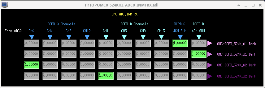
New h1iopomc0 and h1omc models were installed. A DAQ restart (the first of two) was performed soon afterwards due to INI changes for both models.
h1omc0 uses a custom RCG for duo-tone frequency selection and in the past, filter ramp switching. The models had been built on h1build using the modifed RTS_VERSION and RCG_SRC vars, but the h1iopomc0 model would not start because h1build has a different kernel version to h1omc's boot server (h1vmboot0). The models were rebuilt and installed using h1vmboot0 which fixed the problem.
export RTS_VERSION=5.3.0~~dual_tone_frequency
export RCG_SRC=/opt/rtcds/rtscore/advligorts-5.3.1_ramp
WP12283 Add Locklossalert slow channels to DAQ
Dave:
A new H1EPICS_LLA.ini file was generated containing all the non-string PVs hosted by the locklossalert IOC. This was added to the edcumaster.txt
These channels were added to the DAQ on the second DAQ restart.
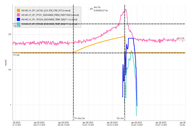
WP12296 Vacuum Ion Pump IOC changes
Patrick, Gerardo, Dave:
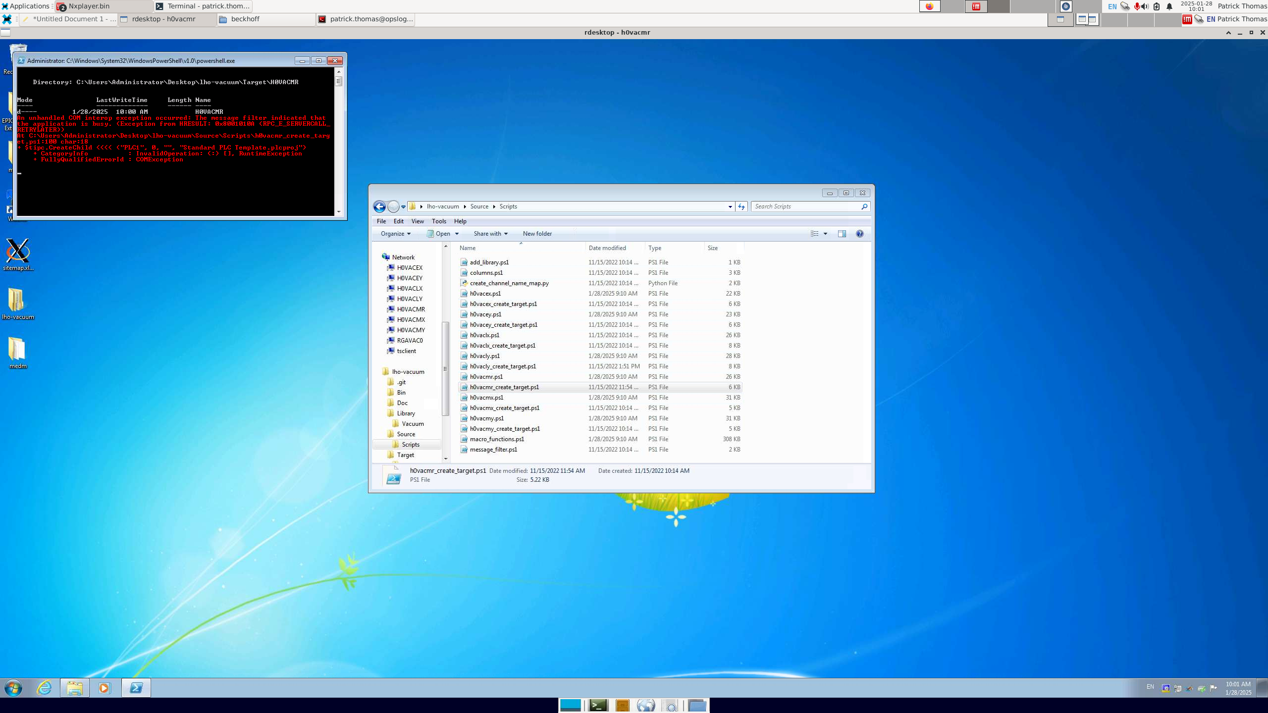
Patrick made code changes on h0vacmr which resulted in some EPICS channels being removed, some being renamed and some being added.
For those being renamed, their minute trend data using the old name is being referenced using the new names.
Following list shows the oldname/newname mapping.
H0:VAC-MR_IP19_CS119_STATUS H0:VAC-MR_IPFCH7_CSH7_STATUS
H0:VAC-MR_IP19_II119_IC_AMPS H0:VAC-MR_IPFCH7_IIH7_IC_AMPS
H0:VAC-MR_IP19_II119_IC_AMPS_ERROR H0:VAC-MR_IPFCH7_IIH7_IC_AMPS_ERROR
H0:VAC-MR_IP19_II119_IC_VOLTS H0:VAC-MR_IPFCH7_IIH7_IC_VOLTS
H0:VAC-MR_IP19_II119_IC_VOLTS_ERROR H0:VAC-MR_IPFCH7_IIH7_IC_VOLTS_ERROR
H0:VAC-MR_IP19_VI119_PRESS_TORR H0:VAC-MR_IPFCH7_VIH7_PRESS_TORR
H0:VAC-MR_IP19_VI119_PRESS_TORR_ERROR H0:VAC-MR_IPFCH7_VIH7_PRESS_TORR_ERROR
H0:VAC-MR_IP20_CS120_STATUS H0:VAC-MR_IPFCA2_CSA2_STATUS
H0:VAC-MR_IP20_II120_IC_VOLTS H0:VAC-MR_IPFCA2_IIA2_IC_VOLTS
H0:VAC-MR_IP20_II120_IC_VOLTS_ERROR H0:VAC-MR_IPFCA2_IIA2_IC_VOLTS_ERROR
H0:VAC-MR_IP20_VI120_PRESS_TORR H0:VAC-MR_IPFCA2_VIA2_PRESS_TORR
H0:VAC-MR_IP20_VI120_PRESS_TORR_ERROR H0:VAC-MR_IPFCA2_VIA2_PRESS_TORR_ERROR
H0:VAC-MR_IP21_CS121_STATUS H0:VAC-MR_IPFCB1_CSB1_STATUS
H0:VAC-MR_IP21_II121_IC_VOLTS H0:VAC-MR_IPFCB1_IIB1_IC_VOLTS
H0:VAC-MR_IP21_II121_IC_VOLTS_ERROR H0:VAC-MR_IPFCB1_IIB1_IC_VOLTS_ERROR
H0:VAC-MR_IP21_VI121_PRESS_TORR H0:VAC-MR_IPFCB1_VIB1_PRESS_TORR
H0:VAC-MR_IP21_VI121_PRESS_TORR_ERROR H0:VAC-MR_IPFCB1_VIB1_PRESS_TORR_ERROR
H0:VAC-MR_IP22_CS122_STATUS H0:VAC-MR_IPFCB2_CSB2_STATUS
H0:VAC-MR_IP22_II122_IC_VOLTS H0:VAC-MR_IPFCB2_IIB2_IC_VOLTS
H0:VAC-MR_IP22_II122_IC_VOLTS_ERROR H0:VAC-MR_IPFCB2_IIB2_IC_VOLTS_ERROR
H0:VAC-MR_IP22_VI122_PRESS_TORR H0:VAC-MR_IPFCB2_VIB2_PRESS_TORR
H0:VAC-MR_IP22_VI122_PRESS_TORR_ERROR H0:VAC-MR_IPFCB2_VIB2_PRESS_TORR_ERROR
DAQ Restarts
Jonathan, Dave:
The DAQ was restarted for the first time soon after the new h1iopomc0 and h1omc models were installed. This was an unremarkable restart except that gds0 had to be restarted twice before their channel lists synced up.
The DAQ was restarted a second time towards the end of maintenance once PCAL was done and the new h0vacmr IOC had been running for a while.
This restart followed a different procedure to permit renaming of the raw minute trend files while the trend writer was inactive (see above listing).
1. Restart 0-leg, except keep tw0 down
2. Restart EDC on h1susauxb123
3. Rename vacuum raw chan files
4. Start tw0
5. Restart gds0 if needed
5 Repeat above for the 1-leg, except EDC restart is not needed a second time.
All went well except I had a copy-paste error in my raw minute trend renaming script, which required me to go onto the trendwriters afterwards and fix a file naming issue.


Tue28Jan2025
LOC TIME HOSTNAME MODEL/REBOOT
08:24:20 h1omc0 h1iopomc0 <<< slow restart of h1iopomc0, it had to be rebuilt on h1vmboot0
08:25:00 h1omc0 h1omc
08:25:40 h1omc0 h1omcpi
08:31:21 h1daqdc0 [DAQ] <<< DAQ restart for OMC model changes
08:31:34 h1daqfw0 [DAQ]
08:31:34 h1daqtw0 [DAQ]
08:31:35 h1daqnds0 [DAQ]
08:31:42 h1daqgds0 [DAQ]
08:32:11 h1daqgds0 [DAQ] <<< gds0 restart
08:32:40 h1daqgds0 [DAQ] <<< gds0 needed a second restart
08:36:36 h1daqdc1 [DAQ]
08:36:48 h1daqfw1 [DAQ]
08:36:49 h1daqtw1 [DAQ]
08:36:50 h1daqnds1 [DAQ]
08:36:57 h1daqgds1 [DAQ]
08:37:30 h1daqgds1 [DAQ] <<< gds1 restart
11:27:24 h1daqdc0 [DAQ] <<< 0-leg restart keeping tw0 down
11:27:39 h1daqfw0 [DAQ]
11:27:40 h1daqnds0 [DAQ]
11:27:46 h1daqgds0 [DAQ]
11:28:26 h1susauxb123 h1edc[DAQ] <<< EDC restart, new VAC MR chans, added LLA chans
11:30:29 h1daqtw0 [DAQ] <<< delayed tw0 start following file renaming
11:31:53 h1daqgds0 [DAQ] <<< gds0 restart
11:33:43 h1daqdc1 [DAQ] <<< 1-leg restart keeping tw1 down
11:33:55 h1daqfw1 [DAQ]
11:33:55 h1daqnds1 [DAQ]
11:34:04 h1daqgds1 [DAQ]
11:35:48 h1daqtw1 [DAQ] <<< delayed tw1 start following file renaming
11:36:36 h1daqgds1 [DAQ] <<< gds1 restart
DAQ changes. left chevron=removed, right chevron=added