I've started building out an LSC guardian library, starting with Kiwamu's PRMI sideband locking guardian module (LSC_PRMIsb.py) I started by making an LSC code library:
USERAPPS/lsc/h1/guardian/lsclib
This is organized as a python package, with sub packages for the various locking configurations. I started by copying Kiwamu's PRMI sideband locking states from LSC_PRMIsb.py into a new module:
USERAPPS/lsc/h1/guardian/lsclib/prmi/sidebandlock.py
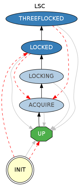
It consists of two top level requestable states, LOCKED and THREEFLOCKED (see attached state graph). The above module is then loaded by a new LSC guardian module:
USERAPPS/lsc/h1/guardian/LSC.py
currently the full contents of which are:
from lsclib.prmi.sidebandlock import *
request = 'LOCKED'
The guardutil utility can be used to inspect the module as is, such as draw the graph and print system info:
$ guardutil print LSC
ifo: H1
name: LSC
path: /home/jrollins/ligo/src/userapps/lsc/h1/guardian/LSC.py
prefix:
usercode:
  /home/jrollins/ligo/src/userapps/lsc/h1/guardian/lsclib/prmi/sidebandlock.py
states (*=requestable):
  0 LOCKED *
  1 UP *
  2 THREEFLOCKED *
  3 ACQUIRE
  4 LOCKING
  5 INIT
We can add new modules for new locking configurations, load them from the main LSC module, and add the necessary edges and states to connect them together.
Eventually we might want to move all of this into lsc/common once it stabilizes a bit. I imagine this is also not the final configuration of this stuff.
I started up the "LSC" node on h1guardian0, and it started up without problem. I left it not doing anything for the moment, but it should be ready to run as is.


ETMX is now realigned for the blue team. Oplev is still off.