hugo.paris@LIGO.ORG - posted 15:13, Thursday 13 February 2014 - last comment - 15:33, Thursday 13 February 2014(10072)
Cleaning Up Foton Files - All SEI platforms starting with BS
SEI Foton files need to be cleaned up by following the procedure described in SEI aLog #370.
I am going to start with BS, and see if reloading the clean foton files while running isolation loops trips BS-ISI or not. If not, I will move on to the other chambers, if it does, I will discuss a time for the update on the other platforms with the ISC commissioners.
Work is performed under WP #4435
Comments related to this report
hugo.paris@LIGO.ORG - 15:33, Thursday 13 February 2014 (10073)
BS tripped whhen reloading the coefficient from the clean foton file. We will have to turn the SEI platforms off, reload the coefficients, and turn them back on. This will happen tomorrow morning.
alexan.staley@LIGO.ORG - posted 15:08, Thursday 13 February 2014 (10071)
MCL-MCF Crossover returned
(Alexa, Sheila)
We have restored the MCL-MCF crossover to the original 15Hz. The mysterious factor of 2 has disappeared by burt restoring the front end LSC model to 02/11/14 at 11pm. We looked through the differences in burt and nothing that would impact the IMC appeared suspicous. At the moment we will not chase down this mystery since the problem has been fixed...
jeffrey.kissel@LIGO.ORG - posted 15:04, Thursday 13 February 2014 (10070)
Moved ISI and HPI ETMX Foton Files to Userapps Repo
While yak shaving today, I discovered that the ETMX HPI and ISI foton files in
/opt/rtcds/lho/h1/chans/
were *not* soft links to the
/opt/rtcds/userapps/release/hpi/h1/filterfiles/
/opt/rtcds/userapps/release/isi/h1/filterfiles/
folders.

I fixed it.

controls@opsws6:chans 0$ ls -l H1*ETMX.txt
lrwxrwxrwx 1 controls controls 60 Feb 13 14:50 H1HPIETMX.txt -> /opt/rtcds/userapps/release/hpi/h1/filterfiles/H1HPIETMX.txt
lrwxrwxrwx 1 controls controls 60 Feb 13 14:51 H1ISIETMX.txt -> /opt/rtcds/userapps/release/isi/h1/filterfiles/H1ISIETMX.txt
lrwxrwxrwx 1 controls controls 60 Jul 15  2013 H1SUSETMX.txt -> /opt/rtcds/userapps/release/sus/h1/filterfiles/H1SUSETMX.txt
controls@opsws6:chans 0$ pwd
/opt/rtcds/lho/h1/chans
controls@opsws6:chans 0$

The filter files are now committed to the repo.
alexan.staley@LIGO.ORG - posted 14:40, Thursday 13 February 2014 (10069)
ALS Noise Budget
(Alexa, Sheila, Daniel)
Attached is a plot of the noise measurements taken from the error point of the EX PLL loop (i.e from IMON of the PFD). The overall PLL noise can be explained by the supressed auxiliary laser frequency noise at low frequency, and is dominated by the shot noise at high frequency. The plot also includes the BBPD dark noise which was subtracted out from the shot noise. There is also a first principles calculation of the shot noise, which is slightly different from the measured shot noise.
There is also a plot of the EX PDH noise measurements. The PDH error signal is a plot of the noise at the error signal of the PDH (i.e. at IMON of the demod). This graph includes the PDH dark noise and shot noise. Notably, the "shot noise" measurement is not pure shot noise. At low frequency there seems to be some fringe wrapping or acoustic noise. The graph also includes the noise from the PLL times the closed loop of the PLL (ie G/1+G). Clearly, some work needs to be done in explaining the noise at low frequency in th PDH loop.
Lastly, to validate the model, I have attached open loop tranfer functions of the EX PLL loop, EX PDH Loop, COMM PLL to VCO loop, and IMC Common Path (w/o COMM Handoff) from the model and data (collected over various alogs). Below are the settings used for the measurements.
I am still working on getting the model to match the MC2 loop and the fast/slow path for the COMM handoff. Once I have validated this portion of the model, I will propagate the end station noise to the corner. I am also working on a documentation summarizing the model and all the measurements taken; this will eventually be posted on the dcc.
PLL Servo Board Settings
Input 1 Pol: NEG
Input 1 Gain: 0dB
Common Compensation: ON
Generic Filter: ON
Fast Option: ON
Fast Gain: -8dB
Boost 1: Off
Rest: Off/Zero PDH Servo Board Settings
Input 1 Pol; POS
Input 1 Gain: -11dB
Common Compensation: ON
Boost 1: On
Rest: off/zero
COMM PLL to VCO Board
Input enable: ON
Polarity: OFF
Gain: 31 dB
Comm filter 1: ON
Comm filter 2: ON
Boost: OFF
Filter: OFF
VCO Compensation: ON
Low pass: ON
Daughter board: OFF
IMC Servo Board
Input 1 enable: ON
Input 1 pol: POS
Input 2 enable: OFF
Input 2 pol: POS
Input 2 gain: 16 dB
Input 1 gain: 9 dB
Common Compensation: ON
Boost 1: ON
Generic filter: ON
Fast Gain: -6dB
Fast enable: ON
Fast Pol: POS
Bypass: ON IMC-L
FM1 (antiwhitening) ON
Gain 1 LSC-MC
All Off
Gain 1 MC2_M3_ISCINF Filter
FM6, FM7 On
Gain 1 MC2_M3_LOCK Filter
FM3, FM9 ON
Gain -300 MC2_M2_LOCK Filter
FM3, FM4, FM10 On
Gain 0.1 MC3_M1_LOCK Filter
FM1, FM2 On
Gain 1
If this story sounds familiar, it's because it sort of is. On 1/23 , I checked all the TMS cables/runs for any shorts between ALL wires, but I didn't check for shorts between the Shield and Ground (Filiberto/Betsy did this for their cables on 1/30 , and happened to check some of our cables and found a short with one of our cables). Today ALL TMS cables were checked for shorts between Sheild and Ground (Betsy assisted). Shorts to ground were found in (2) Cable Runs:
1) TMS SUS (F1, F2, F3, Side) Cable Run
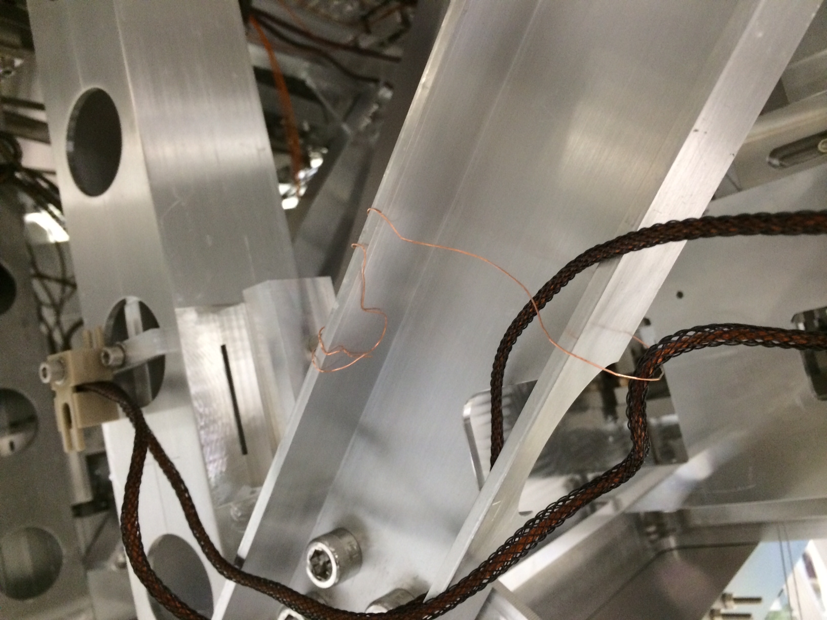
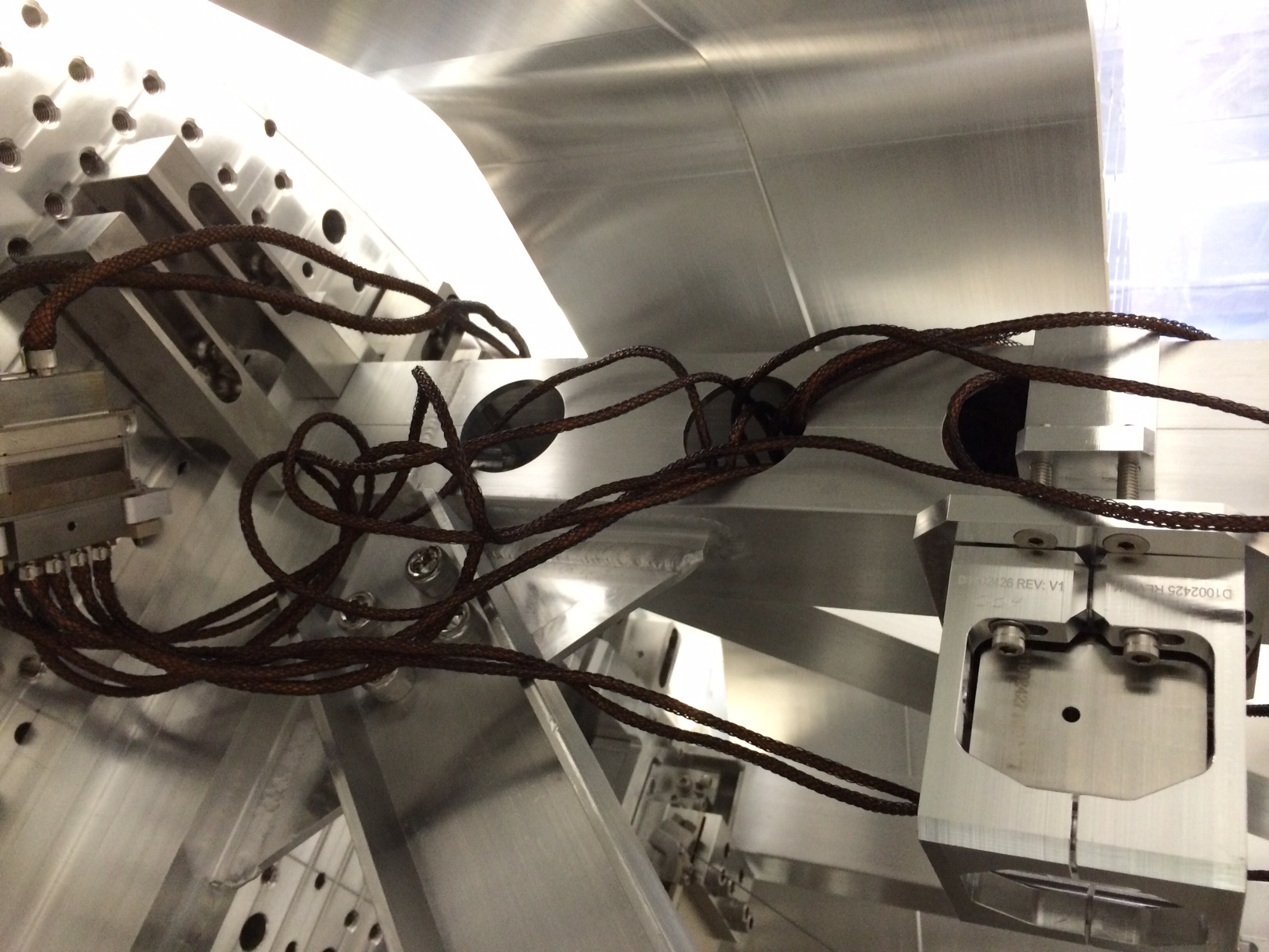
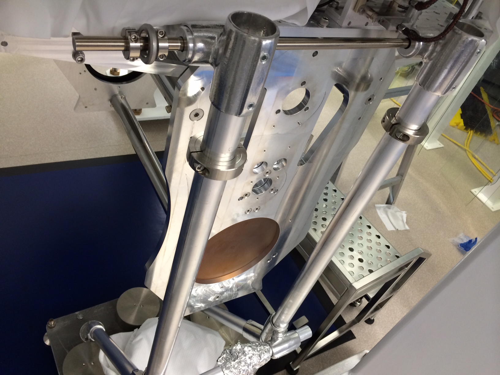
Found the same short Filiberto & Betsy found. We disconnected cables at Cable Bracket on the Optics Table & short went away, so pointed blame to the SUS quadrapuss cable. So, basically just started looking at cable for any kinks, stray shield "hairs", etc. It looked dire at first because there was nothing obvious, but eventually found that the issue was the thin copper wire used to tie these cables to the Upper Structure Frame (see photo#1 of this wire at a different spot). [The end of the wire which wrapped around the structure was poking the Sheild, thus shorting]. We followed what SUS does in this scenario and removed the wire and just stuffed excess cable in the structure beams (see photo#2). Short CLEARLY ELIMINATED.
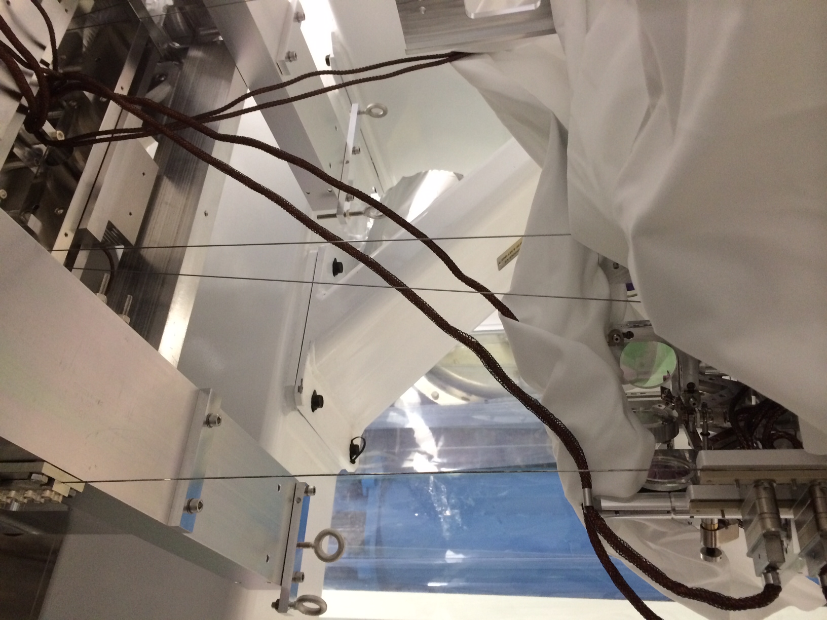
2) Picomotor Cable Run
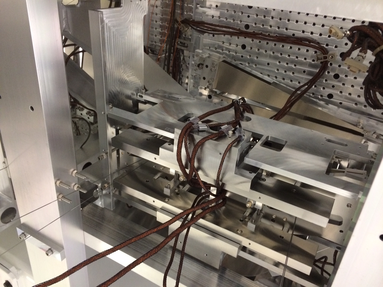
For this one, we were able to trace the short to the "middle" cable which runs from the Table, needles through the Upper Mass, and goes to the Optics Table (this the absolute worst run to have an issue with a cable--see photo#3). Checked obvious places for problems, but couldn't find anything. We noticed from the Upper Mass up to the Optics Table was a fairly straight run and the Clamp on Optics Table (see photo#4) was pretty tight. So this was our best guess at a culprit. I went ahead and loosened the clamp a little.....
BUT, then the thought of possibly altering alignment entered my mind since I've tinkered with cables connected to our suspended Upper Mass (possibly a "D'oh!"). Anyway, I confirmed this clamp wasn't a cause for the short and did my best to restore these cables/cable clamp. I then just looked at how the cable hung under the Upper Mass, and this is turned out to be the issue (somewhere between the Upper Mass bottom clamp and the Cable Bracket on the table---this cable shorts. there's not a lot of slack here so it's probably because it's a little tight). I was able to move the cable around a little and it managed to stop shorting. Then I forgot we like this cable run through a Cable Post. Using this pulled the cable a little tight and caused shorting again (!), after some cussing and magic the short disappeared---we just can't breathe on the cable. Short SORT OF ELIMINATED.
All other cables should be OK. I noticed that a pair of cables pinged briefly with a short, but Richard mentioned this is probably a capacitive effect (we'd need to look at the cable to confirm....apparently, some TMS/ISC cables don't follow the LIGO standard for wiring/shield). At any rate, we called it good and left these cables coiled on Stage-0.
Dressed D1000225 Which Is Replacing Damaged D1000223
Grabbed this cable from the Optics Table and dressed it on the ISI following the path Jim used for similar TMS cables. Note: I forgot to screw in screws on connector which connects to in-vac side of feedthru (heads of these screws protruding has been noted to cause shorts).
TMS Balance Masses Secured
One thing we forgot to do after our alignment work from Tuesday, was secure the balance masses located under the TMS Table. I tightened the Pitch Masses (the Roll set screw was already tight).
Oh, and also took photo of Swing Stop Cart which was installed yesterday (photo#5)
richard.mccarthy@LIGO.ORG - posted 13:43, Thursday 13 February 2014 (10067)
LHO Humidity Plot for 400 days
The plot is the Humidity sensors for the PSL diode room chiller room PSl Enclosure for the past 400 days. For the most part we are okay. When we are well below freezing we dip quite low.
DAQ restart was messy, it glitched the DAQ data from several front ends, which needed their mx streamers to be restarted. The models affected were:
h1asc0, h1oaf0, h1susex, h1iscey, h1pemmx, h1susauxh2, h1susauxh34
david.barker@LIGO.ORG - posted 12:34, Thursday 13 February 2014 (10061)
ASC IPC errors from new LSC model
The h1asc model has dolphin IPC errors for the following LSC channels: H1:LSC-ASC_SASY90 and SPOP18. Looking at the new h1lsc model is appears these channels have been renamed to

H1:LSC-ASC_ASAIR_B_RF90_I
H1:LSC-ASC_POPAIR_B_RF18_I

The h1asc model needs an update to use the new IPC channels.
david.barker@LIGO.ORG - posted 11:17, Thursday 13 February 2014 (10058)
Splitting LSC model over two models has fixed the IPC errors to the end stations
Not sure if we officially ALOGed this, but splitting the single lsc model running at 40uS into two models running at 23uS and 18uS (lsc and lscaux respectively) has fixed the occasional RFM IPC error seen at the end stations SUS and SEI. There have been zero errors at either end station in the past 31 hours. Previous error rate was one every 20 mins.
lisa.barsotti@LIGO.ORG - posted 10:18, Thursday 13 February 2014 (10056)
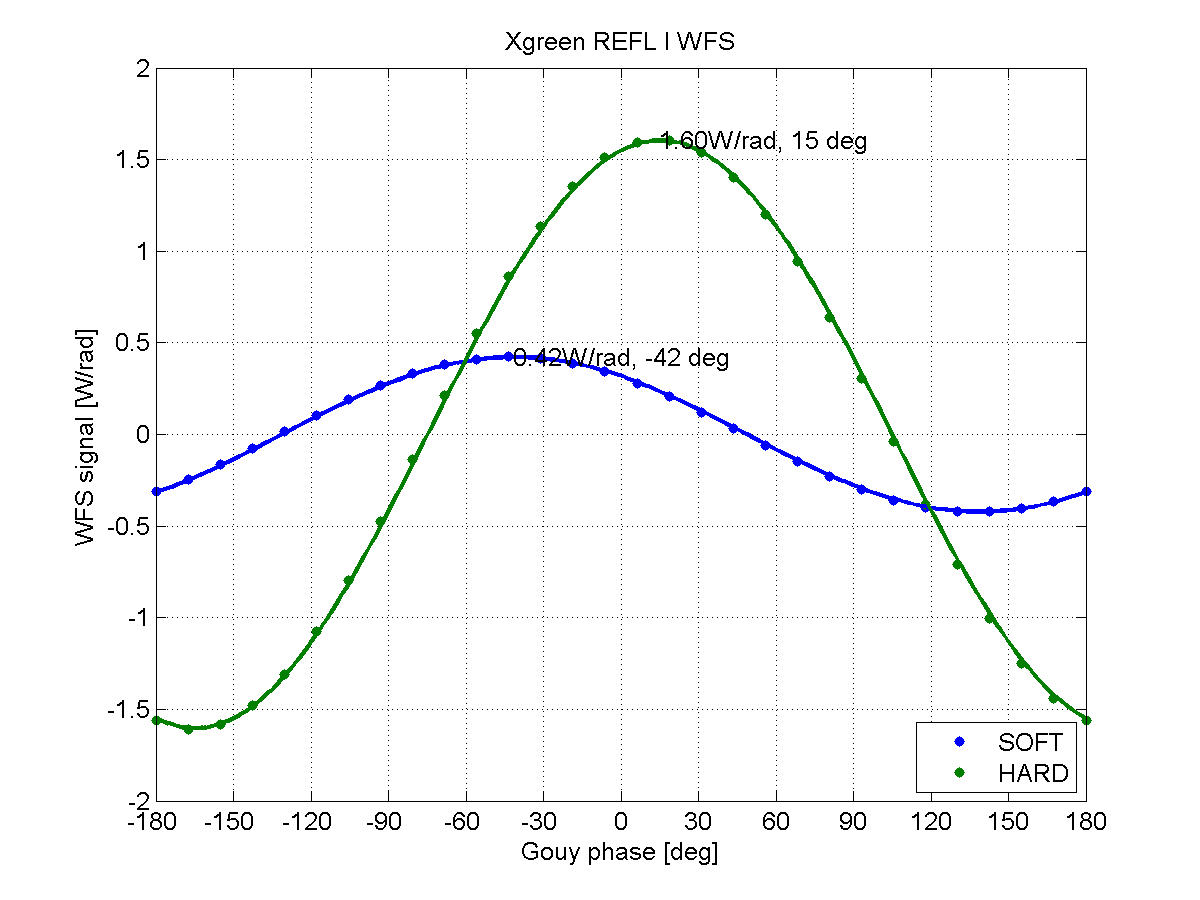
Signal amplitudes for Xgreen REFL WFS
Written by Yuta
I calculated the signal amplitudes for Xgreen REFL WFS. The WFS signal amplitude ratio for SOFT mode and HARD mode is 1:3.8. The Gouy phase separation is 57deg.
Attached figure shows Gouy phase dependence of the WFS signal from both modes. Dots are from Optickle simulation and lines are from analytical calculation.
In my analytical calculation, it assumes high finesse cavity. So, amplitudes are scaled to fit Optickle results in this plot. The ratio of SOFT/HARD or relative Gouy phase does not change. (see Appendix A of T1300497 for more details)
Parameters I used are listed below.
[Parameters]
wavelength: 532 nm
sideband freq: 24.389319 MHz (alog #9708)
modulation depth: 0.1i
input power: 30 mW
power on QPD: 3 mW
cavity length: 3994.4704 m (alog #9626)
ETM RoC: 2241.54 m (alog #9381)
ITM RoC: 1939.52 m
ETM green trans: 38%
ITM green trans: 1%
hugo.paris@LIGO.ORG - posted 10:15, Thursday 13 February 2014 (10057)
SEI WD plotting Software Cannot Access NDS server
The SEI wd plotting software was working at the begining of the week and stopped working 2 days ago, prior to the HAM-ISI update. The script reports issues getting data from the NDS server:
Called with arguments: subsystem='HAM', debug=False, lookback=20, chamber='HAM3', lookforward=15, device='CPS', rough_trip_time=
2014-02-13 09:59:29,110 : WDTripPlotter :
Discovering true watchdog trip time...
2014-02-13 09:59:29,110 : BufferDict :
No NDS host and/or port specified.
2014-02-13 09:59:29,110 : BufferDict :
Found host and ports in NDSSERVER environment variable:
h1nds0:8088
h1nds1:8088
2014-02-13 09:59:29,111 : BufferDict :
Attempting to establish a connection with NDS server at h1nds0:8088
2014-02-13 09:59:29,115 : BufferDict :
Established connection.
2014-02-13 09:59:29,115 : BufferDict :
Buffers requested at start time 1076291510 and end time 1076291512 for the following channels:
H1:ISI-HAM3_WD_MON_STATE_IN1_DQ
2014-02-13 09:59:29,116 : BufferDict :
Trying to recover from error by clearing nds2 cache...
2014-02-13 09:59:33,318 : BufferDict :
Buffers requested at start time 1076291510 and end time 1076291512 for the following channels:
H1:ISI-HAM3_WD_MON_STATE_IN1_DQ
2014-02-13 09:59:50,313 : BufferDict :
NDS server cannot retrieve data for at least one of the following channels:
H1:ISI-HAM3_WD_MON_STATE_IN1_DQ
2014-02-13 09:59:50,313 : WDTripPlotter :
Unable to create BufferDict(['H1:ISI-HAM3_WD_MON_STATE_IN1_DQ'], 1076291510.0, 1076291512.0, wd_state_mask=[True], abs_threshold_mask=None, host=None, port=None).
arnaud.pele@LIGO.ORG - posted 23:00, Wednesday 12 February 2014 - last comment - 14:32, Thursday 13 February 2014(10049)
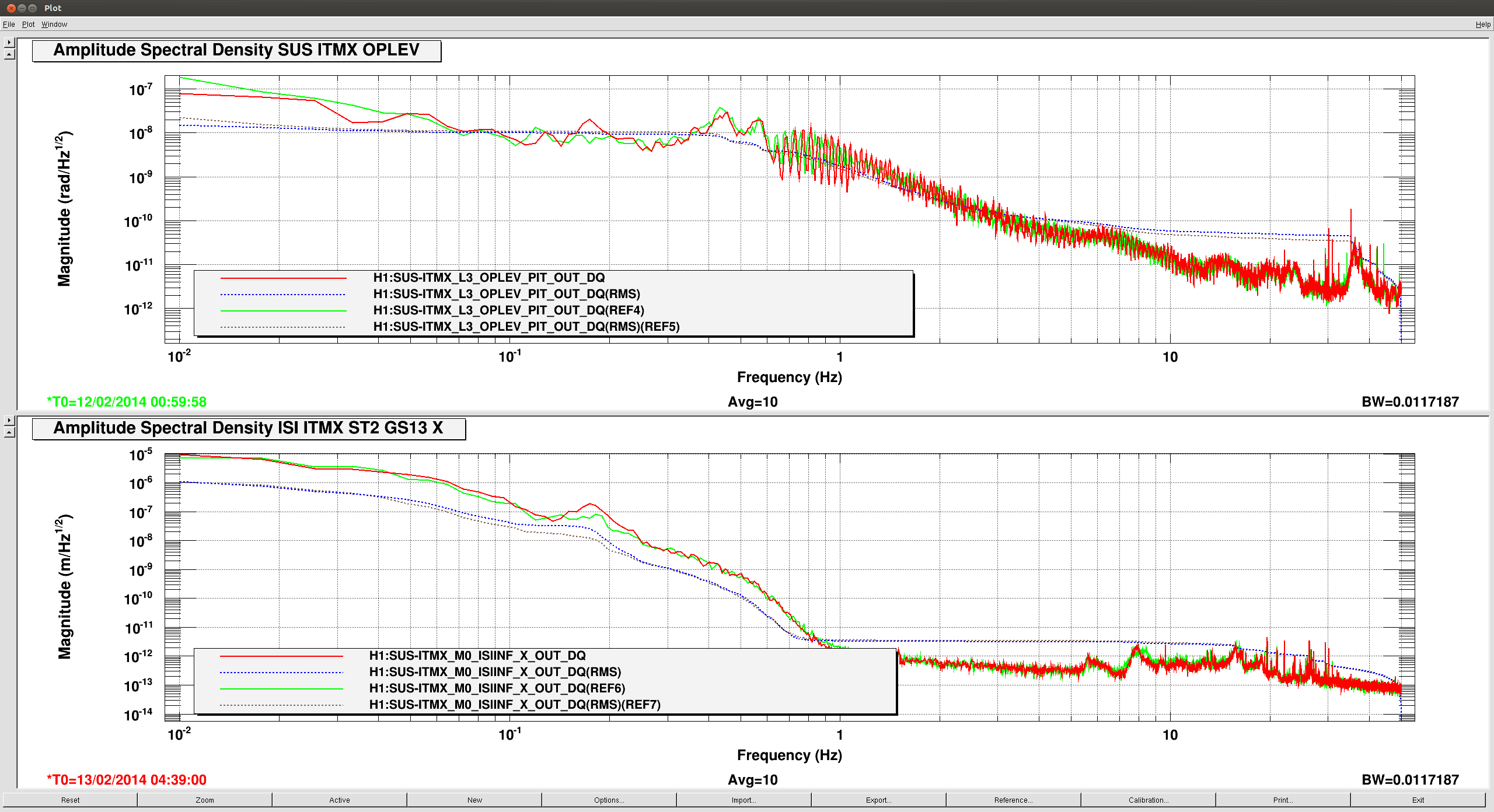
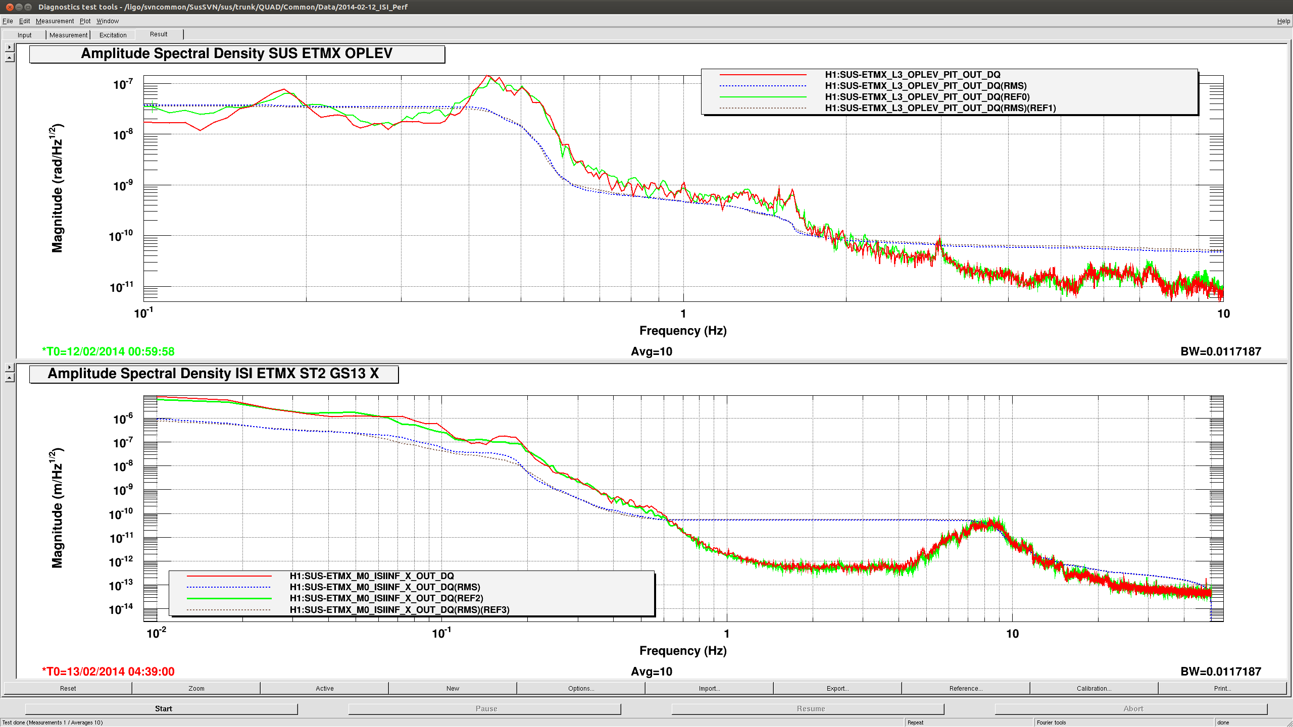
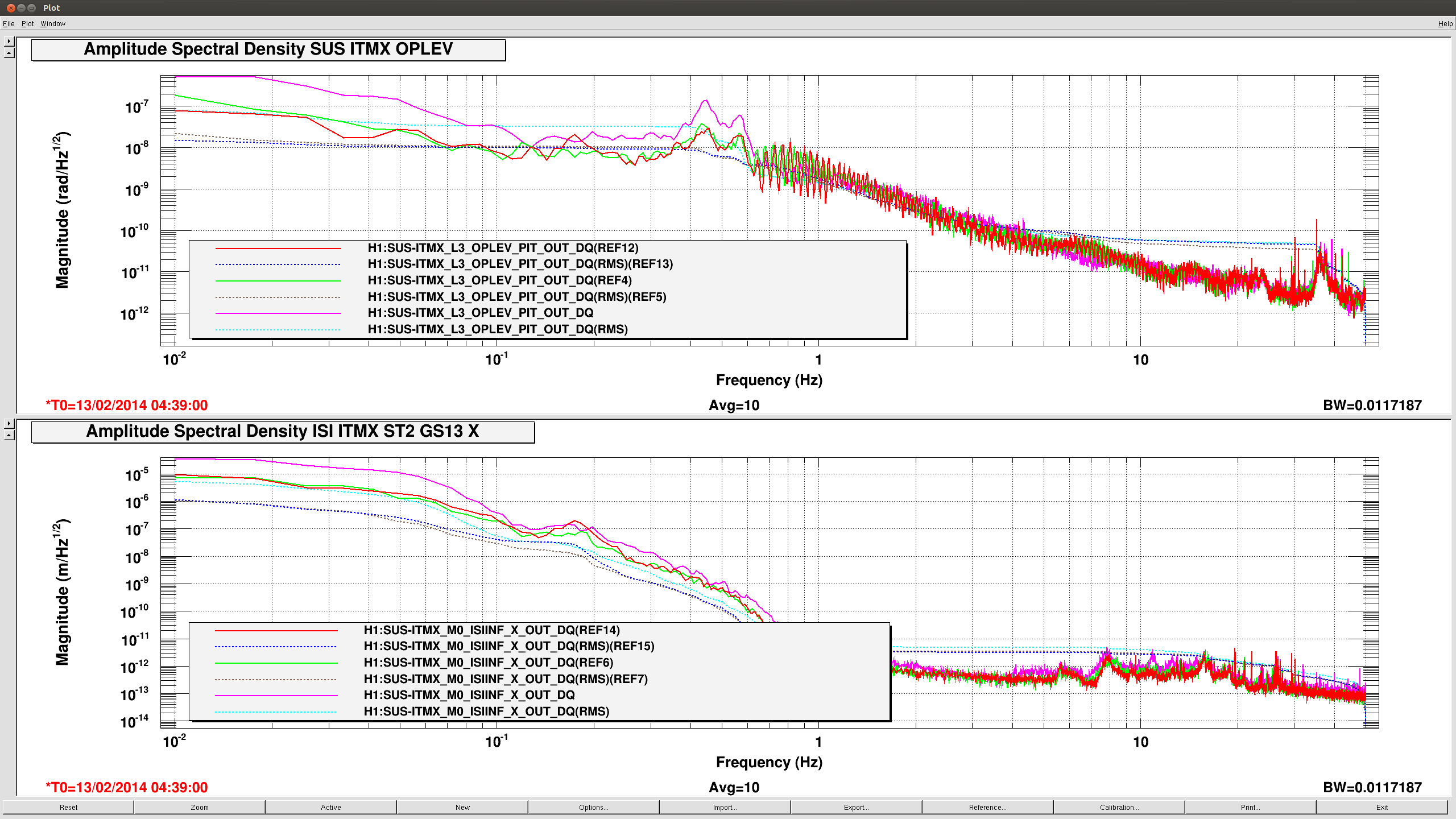
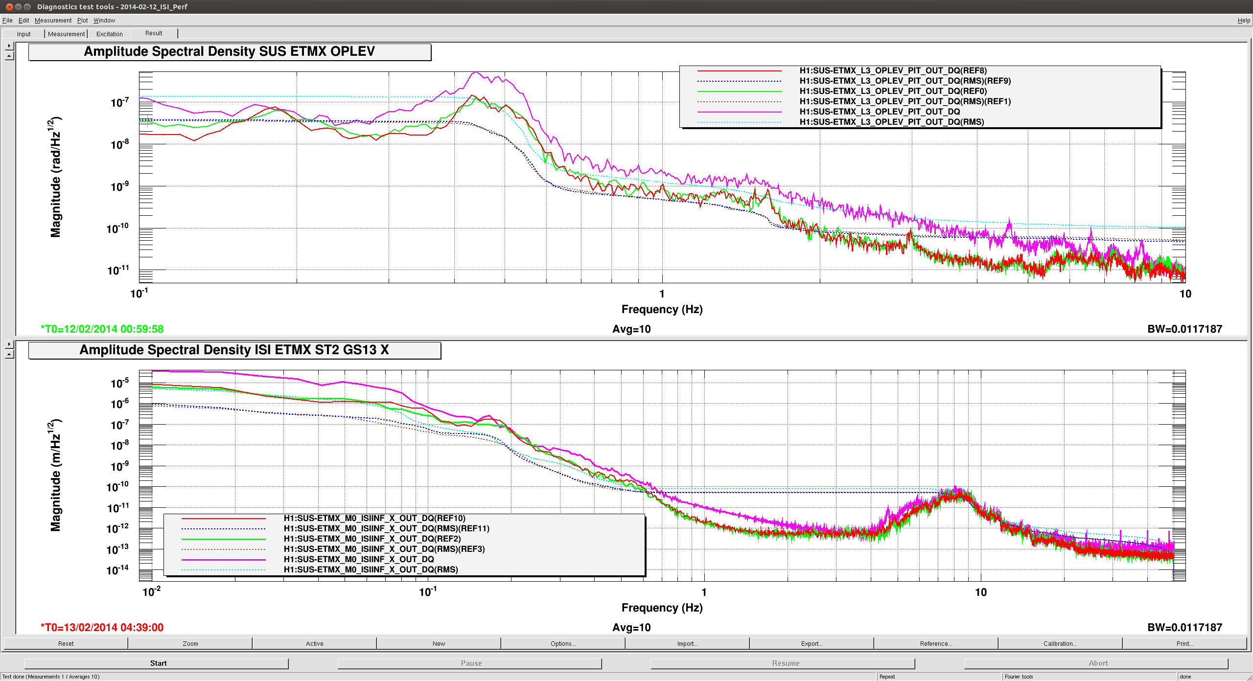
ISI performances consistent
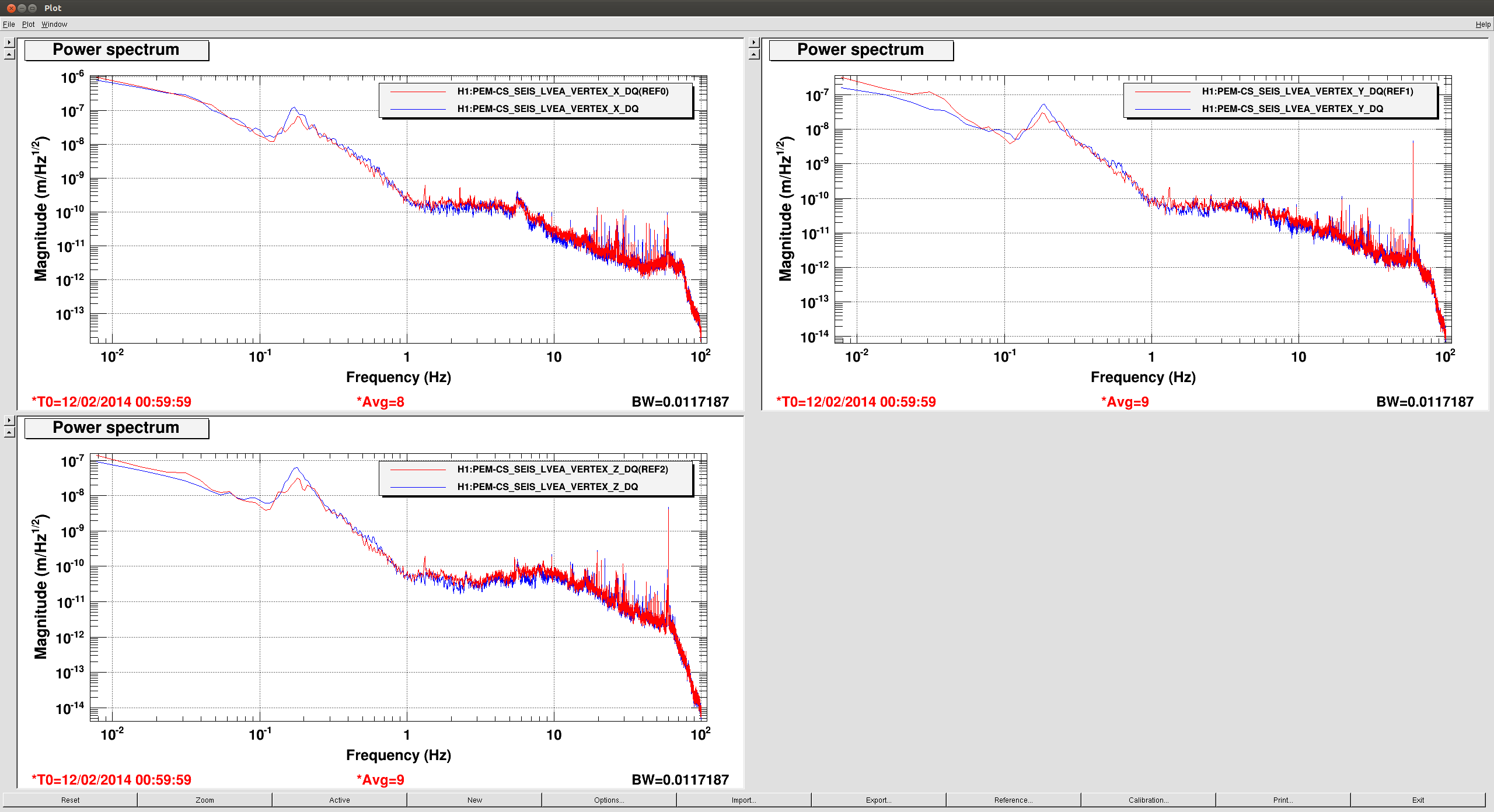
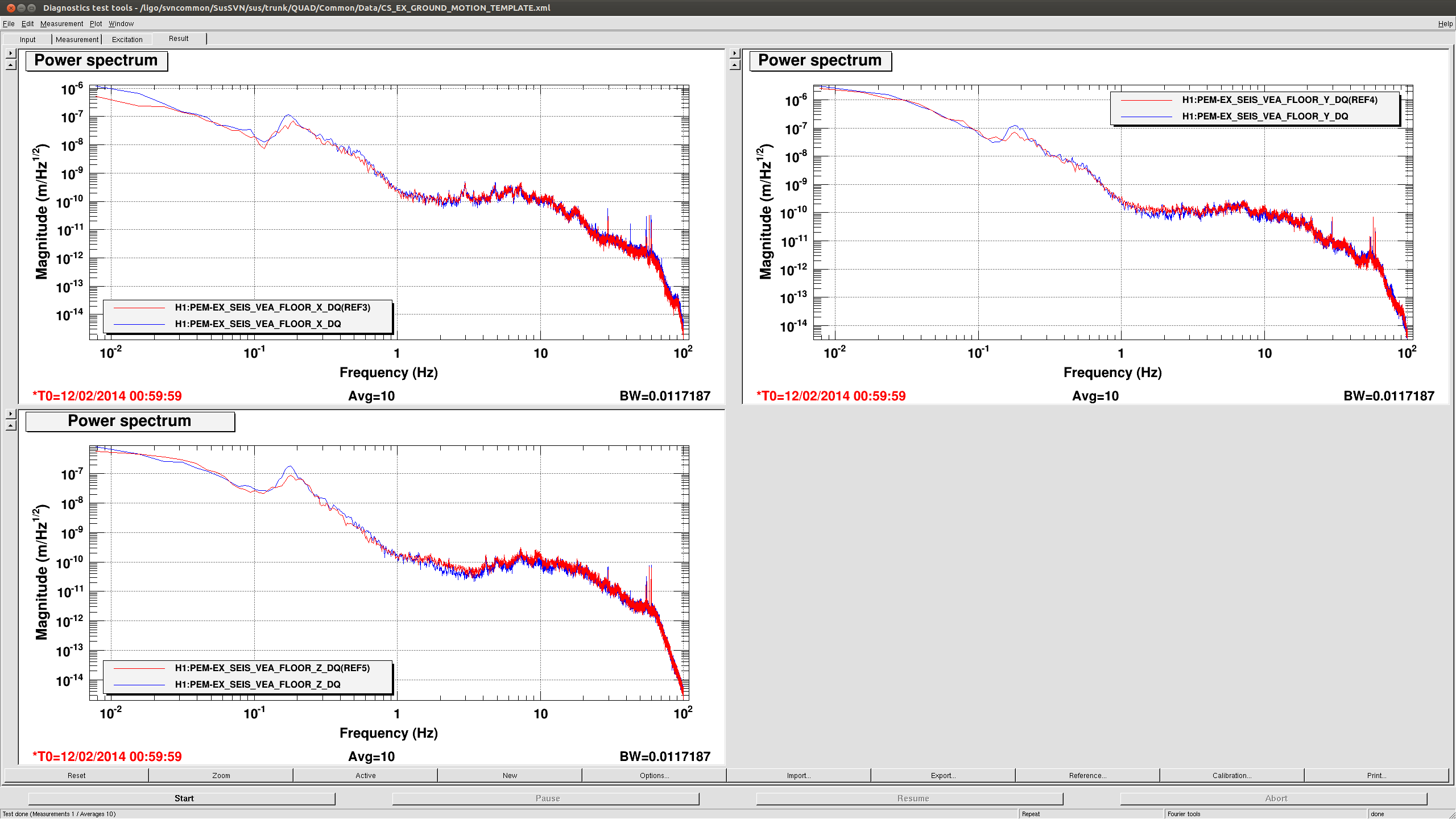
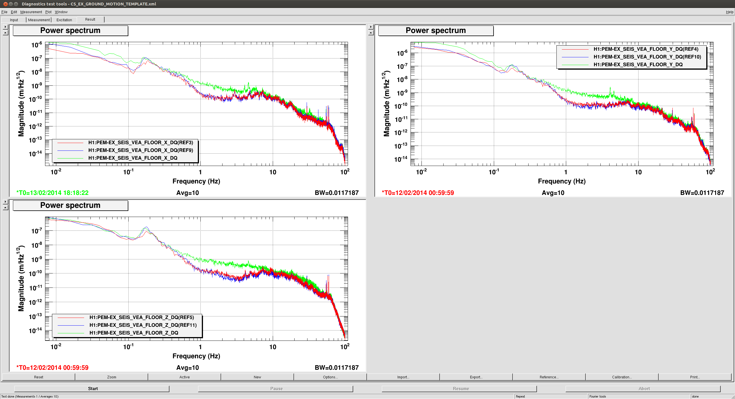
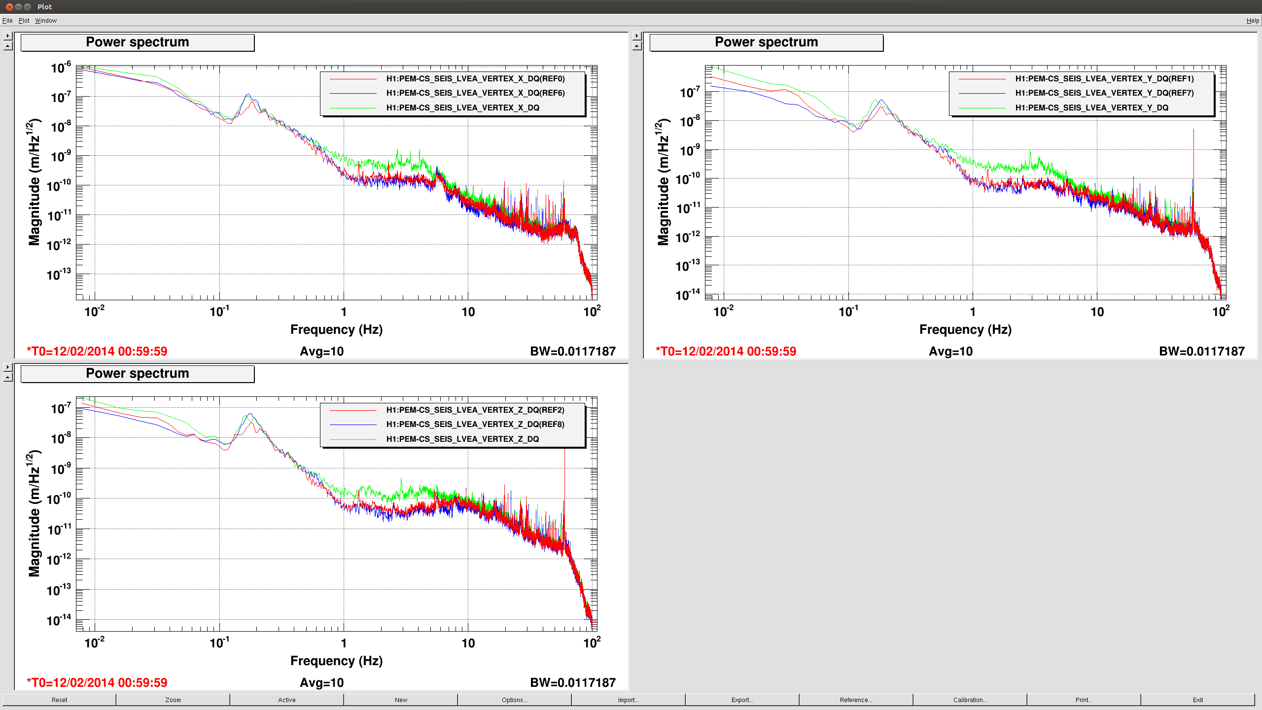
Performances of the ETMX and ITMX ISI were consistent between yesterday evening and this evening, cf the first two attached plots. Although, the ground motion was not that different (cf comparison of the seismometers in PEM_CS and PEM_EX).
First two attachements are showing a comparison of oplev Pitch and ST2 GS13 for ITM and ETM
yesterday night in green (gps 1076202015 2014-02-12 01:00:00 UTC)
this evening in red (gps 1076301556 2014-02-13 04:39:01 UTC)
Last two attachements are a comparison of the seismometers in Corner station and End X
yesterday night in red (gps 1076202015 2014-02-12 01:00:00 UTC)
this evening in blue (gps 1076301556 2014-02-13 04:39:01 UTC)
Images attached to this report
Comments related to this report
arnaud.pele@LIGO.ORG - 14:32, Thursday 13 February 2014 (10062)
I added to yesterday's plot the motion of the ground and ISI from this morning (gps 107636178), in a noisier environment (between 0.5Hz and 8Hz and below 0.1Hz, due to wind ?), see green curve in the PEM signals (PEM_EX PEM_CS) and pink curve in ISI signals (ITMX_perf and ETMX_perf).
sheila.dwyer@LIGO.ORG - posted 20:38, Wednesday 12 February 2014 - last comment - 09:40, Thursday 13 February 2014(10040)
ETMX hepi trip, RY
I caused a HEPI trip this evening, messing with arm cavity slow feedback to HEPI.
While trying to restet this, I once again became annoyed by how the isolate script sets the current setpoint to something other than the target setpoint for Ry and RZ. Forgetting this is part of why it took us several hours to recover from the hepi pump trip this afternoon, and it seems like by continuing to have the script do this we are shoting ourselves in the foot. I have heard that the script does this because of fear that HEPI can't handle these large offsets, but we have been using these large target positions for more than a month, so it seems HEPI can handle them. If that's true, is it possible to fix this script?
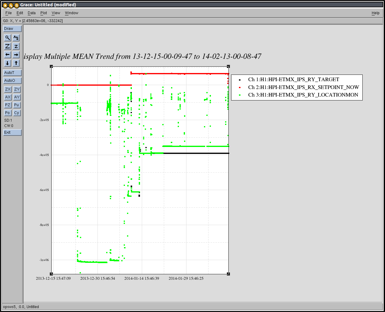
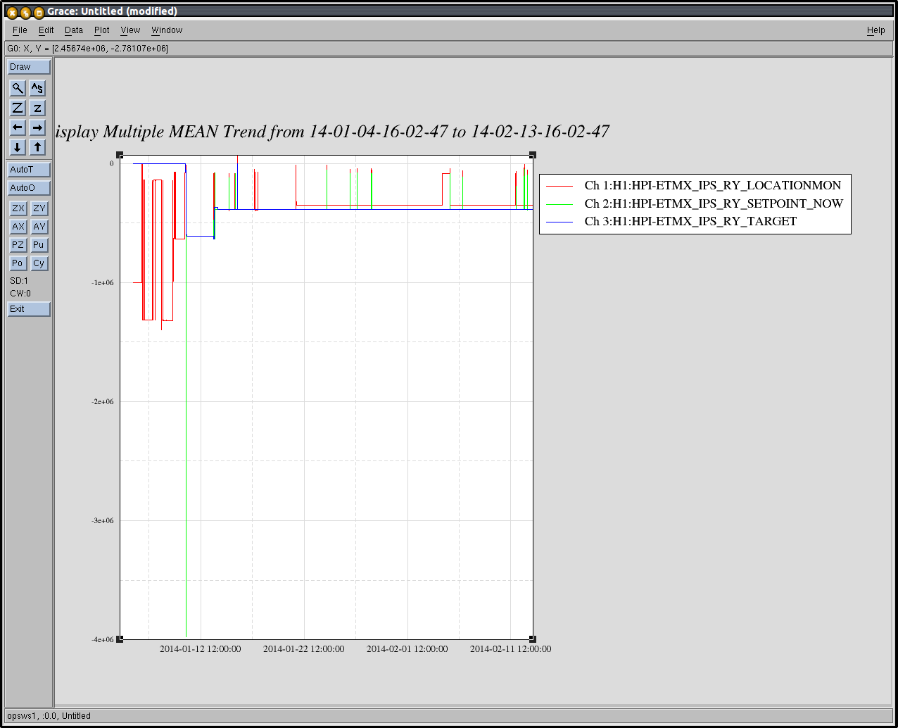
Having a closer look at the offsets, I noticed that the location was not coming back to the set point even after waiting a long time. I attached a plot of the target location over the last 60 days, it has really never been at the set point.
AS far as I understood, this after noon after our long struggle to get ETMX back after the hepi pump trip, Jim got it back one DOF at a time using 250mHz blends on stage 1, Tcrappy on stage 2, and using the 60 Hz notch in the stage 2 controllers (which is for level 3 but while we are still using level 2 controlers we need to engage FM5 by hand). (correct me if I'm wrong Jim)
Instructions for what worked for me now are:
HEPI:
untrip watchdog
Comands 2, Isolate level 1
Important! Check that DC bias current setpoints match the target setpoints.
ISI:
Set T240 watchdog thresholds to something large
Set stage 1 blends to 250, isolate level 3.
Wait a long time, get distracted by other work, come back in a half hour....
change stage 1 blends to Tcrappy
Isolate stage 2 level2 with Tcrappy
All set!
Images attached to this report
Comments related to this report
jeffrey.kissel@LIGO.ORG - 21:53, Wednesday 12 February 2014 (10044)
For the record, it's not that *HEPI* can't handle the large offsets, it's that the Stage 1 T240s on the BSC-ISI can't handle the large offset without saturating, and therefore tripping the ISI's watchdog. The seismic group has heard this complaint loud and clear and is considering if they even need to include the T240s in the watchdog system.

We promise we're trying to make it better!
sheila.dwyer@LIGO.ORG - 22:14, Wednesday 12 February 2014 (10047)
I forgot to say, the reason I was messing with the feedback from ISC to HEPI in the first place was that Brett and I noticed while he was making his measurement that the tidal relieve servo was unstable....
I will try to fix this in the morning.
hugo.paris@LIGO.ORG - 09:40, Thursday 13 February 2014 (10055)
Like Jeff said, we limit the transfer of the Target of HEPI in the Current Setpoint to 500 nrad to prevent saturating the ISI's T240s. One has then to copy the targets into the current setpoint manually if he wants to override this. We could consider removing this limit if we increased the T240 WD thresholds on the ISI at the beginning of the turn on process (starting with HEPI), and had the T240s removed from the blend when turning the ISI on.
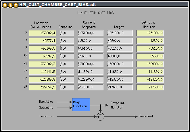
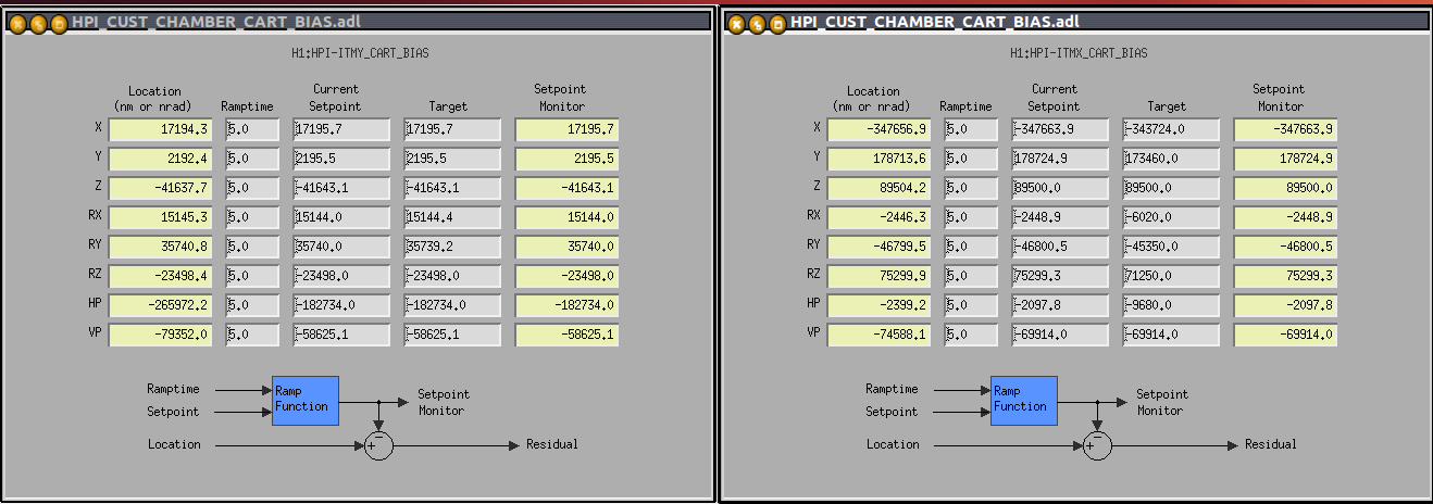
Sheila mentioned another interesting behaviour that we noticed yesterday: even when the Target and Current Setpoint agree, the position on RY does not go all the way to the setpoint value along RY on ETMX. (See attached plot, and Cart Bias MEDM screen). It is not the case on ITMY and ITMX HEPI, but none of them request such high target values (see attached Cart Bias MEDM sceeens for HEPI ITMX and ITMY). One could argue that parts of HEPI may start contacting (each HEPI has a slightly different Range Of Motion which depends on how it was set up) and prevent the servo loops from pushing HEPI to the requested Current Setpoint. This would probably make the position loops go unstable though, and it is not the case. As a side-test, we increased the value of the current setpoint on RY to see if the location would follow and it does, which indicates that HEPI is not stuck contacting.
This oddity has been going on for 60 days, but has also remained consistent throughout, even though HEPI, and its pumps, got restarted more than once. HEPI alignment along RY, once controlled, has not changed for those 60 days.
As far as having trouble turning the ISI on, the shift between the floating, and requested controlled position are quite high. We tried making this smaller, which made the ISI turn on way easier, and request the needed alignment to SUS, which seems to have worked. Should we do it this way from now on, for the sake of making the ISI turn on process more repeatable on ETMX?
mark.barton@LIGO.ORG - posted 13:29, Wednesday 12 February 2014 - last comment - 09:31, Thursday 13 February 2014(10028)
HTTS TFs started
I swapped in a new HTTS filter file with corrected dewhitening filters (what claimed to be 10:0.4 had actually been 40:1.6). I checked that RM1 and RM2 still damp stably.
I've started on a round of undamped TFs on RM1 and RM2 to check that I get the expected results without post-hoc corrections.
Comments related to this report
mark.barton@LIGO.ORG - 09:31, Thursday 13 February 2014 (10053)
The TFs were taken successfully. The raw data was processed with meas.badFilt = '' (no post-hoc filter correction) and meas.E1201027 = true (coil driver resistors replaced):
These data sets are plotted in the attached PDF with the latest L1:RM1 and L1:RM2 results and the immediately previous H1:RM1 and H1:RM2 results of 12/20/13. As expected, the new results without post-hoc filter correction agree with the earlier results with correction, showing that the new H1SUSHTTS.txt file is good. (It has been committed.)
The agreement with the model is good for H1:RM1 so this new data (2014-02-12_1330) can count towards Phase3b testing. The RM2 data shows the same strong coupling of L into Y as the last few measurements, and this needs to be investigated at the next vent.
LLO should impement the same fix as soon as convenient. Specifically, in L1SUSHTTS.txt, all the ???_M1_OSEMINF_?? modules should have Section 1 set to have label '10:0.4' (probably that way already) and filter zpk([10],[0.4],1,"n") (will have been zpk([40],[1.6],1,"n")).
corey.gray@LIGO.ORG - posted 20:07, Tuesday 21 January 2014 - last comment - 13:00, Thursday 13 February 2014(9413)
EY TMS In-Vac Cabling Work
Replaced original 4-story Cable Bracket (CB) with 2-story CB1 & CB2 (positioned roughly to where they should be according to Layout drawing and with what SUS allowed).
Performed continuity/elec short tests for the four ISC TMS Seismically Responsible Cables. One of them had a short (D1000223 s/n S1104078's pin 13 & 16); Keita notified me that pin 13 is picomotor HV, and pin 16 is not used....so we should be OK.
Starting to connect these cables to CB1 & CB2, and with the cables which come from the TMS. Will then run another continuity test.
Will do the same for the SUS TMS cables on the other side of the table.
Comments related to this report
corey.gray@LIGO.ORG - 13:00, Thursday 13 February 2014 (10063)

BS tripped whhen reloading the coefficient from the clean foton file. We will have to turn the SEI platforms off, reload the coefficients, and turn them back on. This will happen tomorrow morning.