J. Kissel, L. Barsotti, H. Radkins, J. Warner, R. Mittleman
What started out as a conversation of "I don't trust the optical lever calibration. The performance can't be that good" turned into "Wow, if we can hold that performance, ASC might be OK..." Excellent work, Jim, Hugh, and Rich.
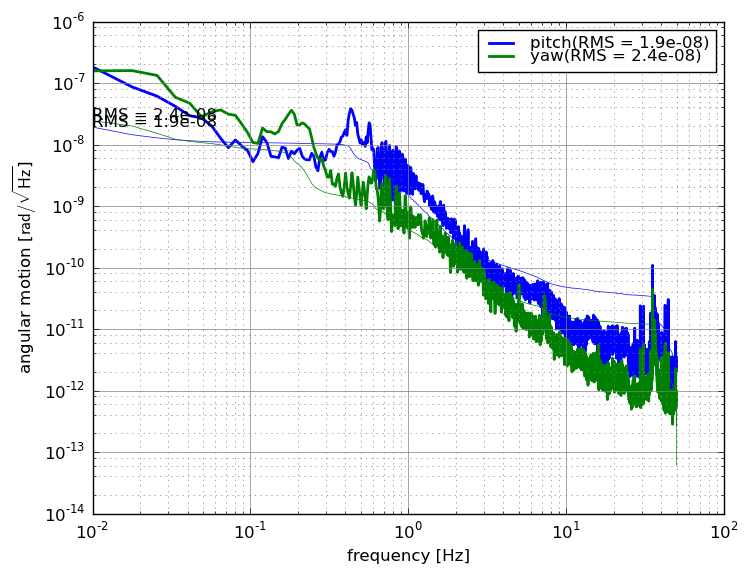
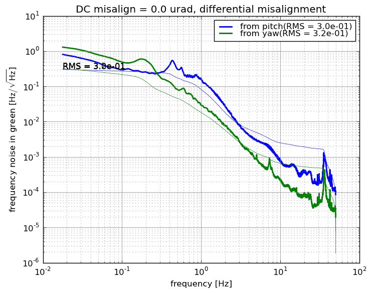
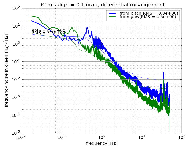
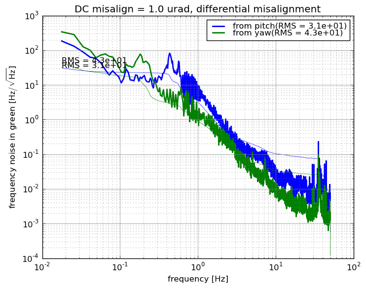
Here're some performance measurements of the H1 SUS ITMX and H1 SUS ETMX as measured by the ISI ST2 GS13s and SUS Optical Levers. The ORANGE shows the current performance, which puts the ITMX and ETMX pitch motion at 20 and 50 [nrad] RMS, and a maximum of 5e-8 and 1e-7** [rad/rtHz] at 0.45 [Hz]. I also attach model predictions for this ORANGE optic motion based on the ISI performance, and we can clearly see the ETMX optical lever spectrum is polluted by length-to-angle coupling and is not reporting the actual motion of the optic, so we should not trust Oplev ETMX as a viable pitch sensor when the ISI is performing as well as it is.
From here on, we need to work on making sure that this performance is consistent. The ground motion (where my only quick indication in the control room is an 80 hour trend of the microseism BLRMS) was consistent between these two better days, so we need to study the performance over longer periods of time to see where we stand in the face of large ground motion.
-------------
I compare three times:
"Controllers" = Isolation Loop Control Filters; "Blends" Isolation Loop Sensor Blend Filters
(2014-02-14 01:00 UTC) TCrappy
ITMX HPI -- "Level 1" Controllers; "Pos" (Position-Sensor-Only) Blends
ITMX ISI -- "Level 3" Controllers; ST1 "TCrappy" Blends (All DOFs), ST2 "100 mHz" XY, "250 mHz" ZRXRYRZ
ITMX SUS -- "Level 2.1" Damping Filters, designed 2013-06-14.
ETMX HPI -- Level 1 Controllers; Position Sensor Only Blends
ETMX ISI -- ST1 Level 3, ST2 Level 2 Controllers; ST1 TCrappy Blends (All DOFs), ST2 "100 mHz" XY, "250 mHz" ZRXRYRZ
ETMX SUS -- Level 2.1 Damping Filters, designed 2013-06-14.
(2014-02-10 01:30 UTC) TCrappy, PRMI Locked
I *believe* this time is in the same configuration as ORANGE, but I'm not positive. Note, here ETMX was misaligned because team red was commissioning the PRMI. I show the spectra anyway because it's good to see a "dark" spectra.
(2014-01-23 21:00 UTC) T100_N0.44
The "best" configuration 2 weeks ago, (from LHO aLOG 9546), before we'd fixed the CPS beat frequency combs (see LHO aLOG 9675), and the 0.5 [Hz] comb from the busted T240 cable (see LHO aLOG 9612)"
ITMX HPI -- "Level 1" Controllers; "Pos" (Position-Sensor-Only) Blends
ITMX ISI -- "Level 1" Controllers; ST1 "T100mHz_N0.44" blends on XY and "750mHz" ZRXRYRX, ST2 "750 mHz" on all DOFs.
ITMX SUS -- "Level 2.1" Damping Filters, designed 2013-06-14.
ETMX HPI -- "Level 1" Controllers; "Pos" (Position-Sensor-Only) Blends
ETMX ISI -- "Level 1" Controllers; ST1 "T100mHz_N0.44" blends on XY and "750mHz" ZRXRYRX, ST2 "750 mHz" on all DOFs.
ETMX SUS -- "Level 2.1" Damping Filters, designed 2013-06-14.
There are several things to note, comparing ORANGE measurements against model:
ITMX (A "wire rehang" QUAD)
- Below 0.6 [Hz], the model is dead-on with the optical lever measurement. With a ~30 [m] lever arm, these ITM optical levers have the smallest longitudinal-to-angle, low-frequency, cross-coupling. Nice! This convinces me (in addition the input spectra I'd modelled in LHO aLOG 9734) that the model is a good predictor for the *real* optic motion in this frequency region.
- Above 0.6 [Hz], (a) we have no idea what that strange fuzz is, and (b) I think both pitch and yaw are ADC noise limited. HOWEVER, I don't understand why the 1-3 [Hz] sensor noise is not visible, if this is the oplev-noise floor. Perhaps the BOSEM sensor noise is better than the stick-curve I use as the input.
- Notice that the BSC-ISI is meeting or beating the aLIGO requirements at all frequencies in this 0.1 [Hz] to 10 [Hz] band. BOOM.
ETMX (A "fiber" QUAD)
- In pitch, I claim that the only motion that is not an artifact of the optical lever sensing are the two bumps between 1-2 [Hz]. Below 0.6 [Hz], the longitudinal-to-angle coupling fundamental to such a short optical lever takes over, and we see mostly longitudinal motion confused for pitch. The remaining bits of the frequency band are electronics / ADC noise of the optical lever.
- This QUAD model DOES over-estimate the first pitch frequency (it predicts it to be 0.56 [Hz], and we've measured it to 0.51 [Hz]), so this, coupled with the L-to-A coupling, is why we don't predict the first pitch mode well at all.
- In yaw, the model prediction is better, especially below 0.6 [Hz] but the remaining spectrum only show hints of the tips of the resonant features.
About the ISI performance:
- Note that both of these chambers still don't have sensor correction. This might help to improve the performance even further in the 0.2 to 0.7 [Hz] band. Nothing amazing, but perhaps another factor of 2 to 3
- We really need a noise budget of the BSC-ISIs to assess what's limiting us in this frequency range. I still have a gut feeling that we're still getting bitten by tilt noise.