I finally got a script working to step the alignment offsets on the IMC mirrors and record the transmitted power drop with MC2trans and IM4trans QPDs.
The idea behind this was to compare the quadratic function for power drop with misalignment with the theoretical function, giving us a means of accurately calibrating the alignment offsets.
The reason I'm interested in calibrating these offsets accurately is for beam jitter measurements using the coupling from jitter to RIN in transmission of a misaligned IMC [see e.g. LHO aLOG entry 8190]. The coupling factor is determined by the slope of the quadratic function, so we can't calibrate jitter measurements made in this way any better than we can calibrate the DC alignment offset.
The first attached plot shows the normalized transmitted power obtained for each individual mirror DOF, from both IM4trans QPD and MC2trans QPD, over "intended" alignment offset. Also included is a plot of the normalized transmitted power from a Finesse model of the IMC over "real" misalignment offset. From these plots we can see that in general the alignment offsets actually applied to the MC mirrors are larger than the intended alignment offsets. However, the measured data is not always symmetric (especially for IM4). This could be due to clipping at the QPDs. The centering on IM4trans is not as good as the centering on MC2trans, so I would be more confident in the numbers from MC2trans.
I fitted a quadratic function P=A(x-h)^2+k to each of the curves. The calibration is then done by scaling the alignment offsets applied to the actual suspensions by sqrt(Amodel/Adata). The second attached plot shows each DOF again, but this time with the x-axis scaled for the measured data to fit the model. I used the scaling factors calculated from MC2trans data since the centering on this QPD was better. For the most part I'd say the data matches the model well after this scaling.
These scaling factors are:
|
DOF |
Scaling factor |
|
MC1 Pitch |
0.7043 |
|
MC1 Yaw |
0.8223 |
|
MC2 Pitch |
0.8572 |
|
MC2 Yaw |
0.8326 |
|
MC3 Pitch |
0.7823 |
|
MC3 Yaw |
0.8588 |
I would propose to include these scaling factors in the calibration of the MC mirror offsets.
The script can be run again at any time to check for any possible changes in e.g. the OSEM coil driver gains over time. It might be beneficial to take more data points at some point too, but the script takes 15mins or so to run as it is (mainly due to the time given for optics to settle between changes of offset). Another improvement would be to step MC1 and MC3 pitch over a larger range, since the transmitted power is actually fairly insensitive to these DOFs. Both these things can be edited in the top few lines of the script.
In case anyone is interested in running this script in future, it is located at opt/rtcds/userapps/release/ioo/h1/scripts/imc/pfulda/IMC_align_calibrate.py
Be sure to run the mcWFSrelieve script located in opt/rtcds/userapps/release/ioo/h1/scripts/imc/ first though!
I attach the analysis scripts here too, including the measured data, Finesse model and results, and other functions used.
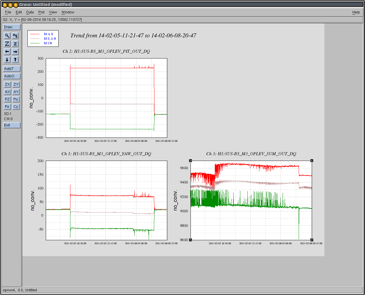
 The attached is the trend.
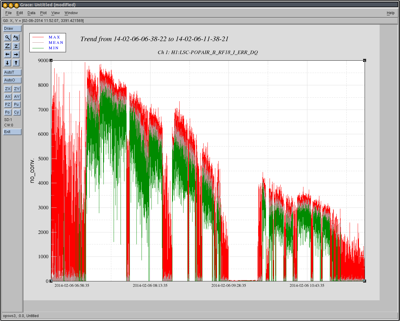