Alexa, Keita, Sheila, Daniel,
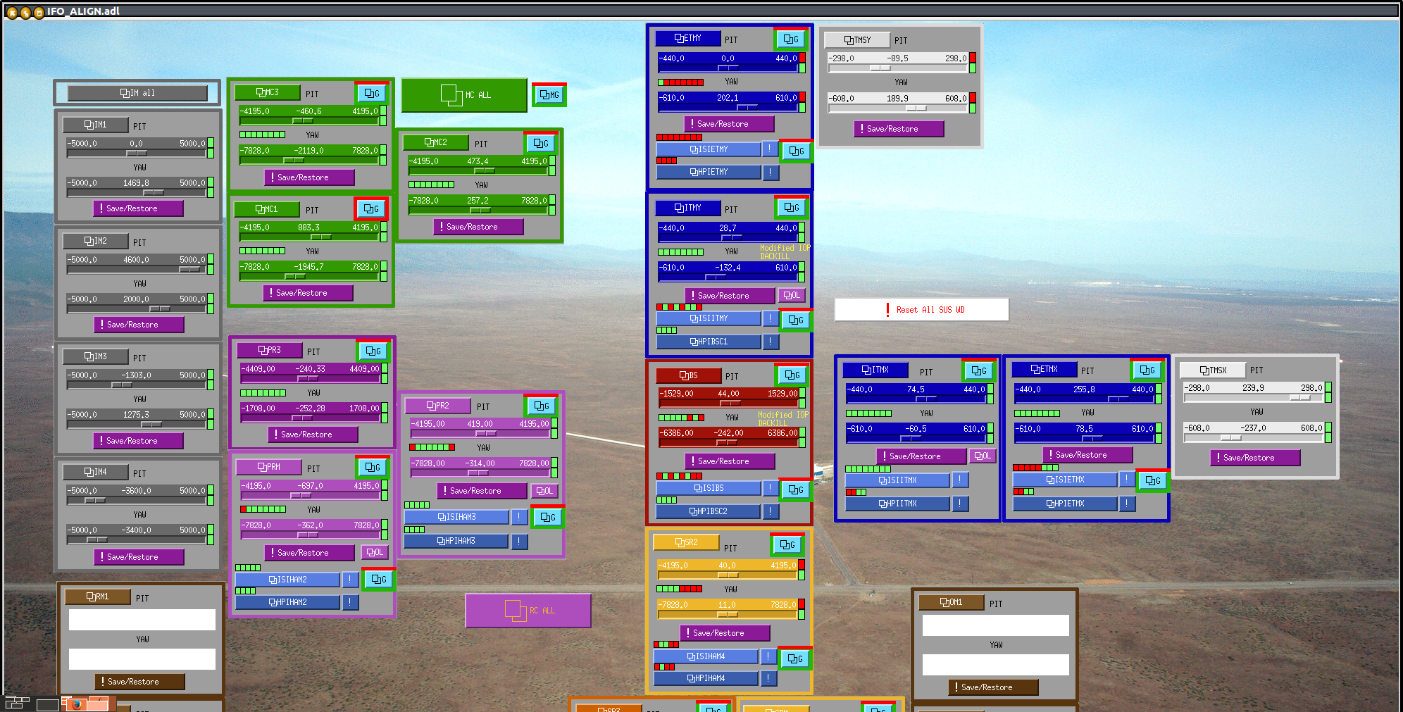
Starting with yesterday's alingment alog 9230, I found some flashing this morning using the transmitted PD. This lead to a clearly visible 00 mode on the ETM camera. The final alingments we ended up with are in the attached screenshots.
The trans PD (ALS COMM) has flashes up to 400 counts, which means that we have about 35 uW (a factor of 10 more than the single shot beam). The refl PD drops from about 19000 counts to about 16000 when the cavity is locked to the 00 mode. There is also a 02 mode that has about 200 counts in transmission, so about half the power of the 00 mode.
It seems as though all the previous alingments where we thought we had fringing were red herrings. I moved the camera on ISCT1 (now using a lens and letting the beam hit a baffle) so that the single shot beam is no longer visible but you can clearly see the cavity modes.
Since the locking was so unstable we thought of trying to feedback to HEPI as was done in HIFO-Y. However, the IPC from the SUS to HEPI has been deleted. We either need to add it back or add an IPC directly from the LSC model to HEPI. Hugo is working on it. However, the situation that we have seems worse than in HIFO Y, there we would run out of range after tens of minutes, today we are running out of VCO range every few seconds. Also, we get about 5 fringes per second, which if it is due to motion of the optic would mean 1um per second motion. We need to investigate if the optics are really moving this much.
Alexa and I went to the end station to look at what was saturating (we are exceeding the VCO input range it seems). While we were there we also had a look at the IQ scatter plot on the scope. One thing is that there is approximately the same amount of signal in I as Q, so this is not a usefull way to try to tune the demod phase. Keita came out and we tried to measure the transfer function from the laser frequency to the demodeulated signals, however we could not because the lock was not stable enough. We also tried to adjust the demod phase while watching the open loop TF, this also wasn't sucessfull because the loop did not stay locked long enough for us to get repeatable measurements.
Alexa and I also looked at the residual AM by misaligning the ITM and looking at the output of the PD. With the ITM misalinged, we have -33dBm of residal AM at the input to the demod, with it aligned we get some thing around -17dBm.
Stefan is currently investigating the ISI performance.
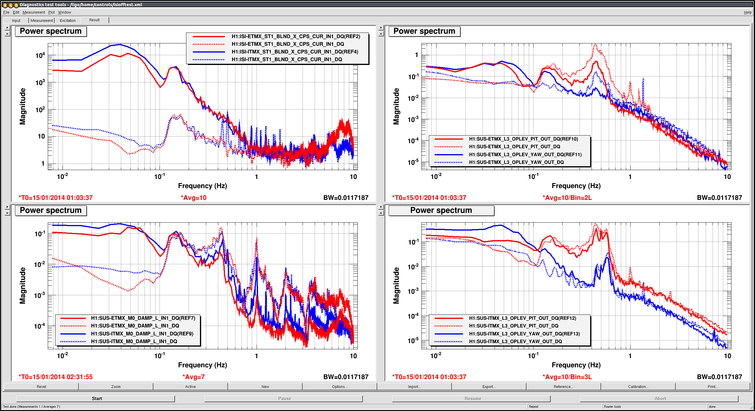
We started turning off ISI isolation to see how good or bad the length isolation is, and attached is the comparison of ISI isolation for both ITMX and ETMX ON (dashed lines) VS OFF (solid lines).
On: 2014/01/15 01:03:37 UTC
Off: 2014/01/15 02:31:55 UTC
We haven't looked at the seismometer, but just by looking at the fringe moving around it was obvious that ISI isolation makes the low frequency length motion much, much larger, and both SUS BOSEMS (left bottom) as well as the ISI CPS (left top) confirm this.
This looks too bad to be true, I guess ISI might have been in some bogus state when they were supposed to be in level 1 isolation.
OTOH, when ISI isolation was on the angular motion was smaller, and the oplevs (right, top=ETM, bottom=ITM) show that the problem was mostly in EX at about 0.4-0.5Hz. Again the same caveat (we're not looking at seismometer) applies.
Stefan is still playing with all available ISI isolation levels to in a hope to find a good compromise.