Jim and Dave
Over the weekend the HWWD unit attached to ITMY has been giving LED error status roughly once an hour but randomized. Each error is only a few seconds in duration. The sister unit in the DTS has shown no errors (we installed a long 37pin cable on friday). This afternoon at 12:50 we replaced the ITMY unit (S1301699) with the DTS unit (S1301706). The only issue with the swap is that the 706 unit did not boot up automatically on application of power, we had to press the reset button. On the other hand the 699 unit when powered up in the DTS booted first time every time.
About an hour later we saw an LED error condition on ITMY (now the 706 unit) so the problem seems to be with the ITMY osem/sat-amp/cabling and not the HWWD (the 699 unit now in the DTS has shown no errors). Jim and I went out to the CER and LVEA to verify the monitor cables look ok at 15:18. We noticed that the ITMY M0/R0 sat amp is a replaced unit, the original unit is stored on the BS shelf. Filiburto remembers there was a possible low frequency issue with this sat amp, hence the swap out.
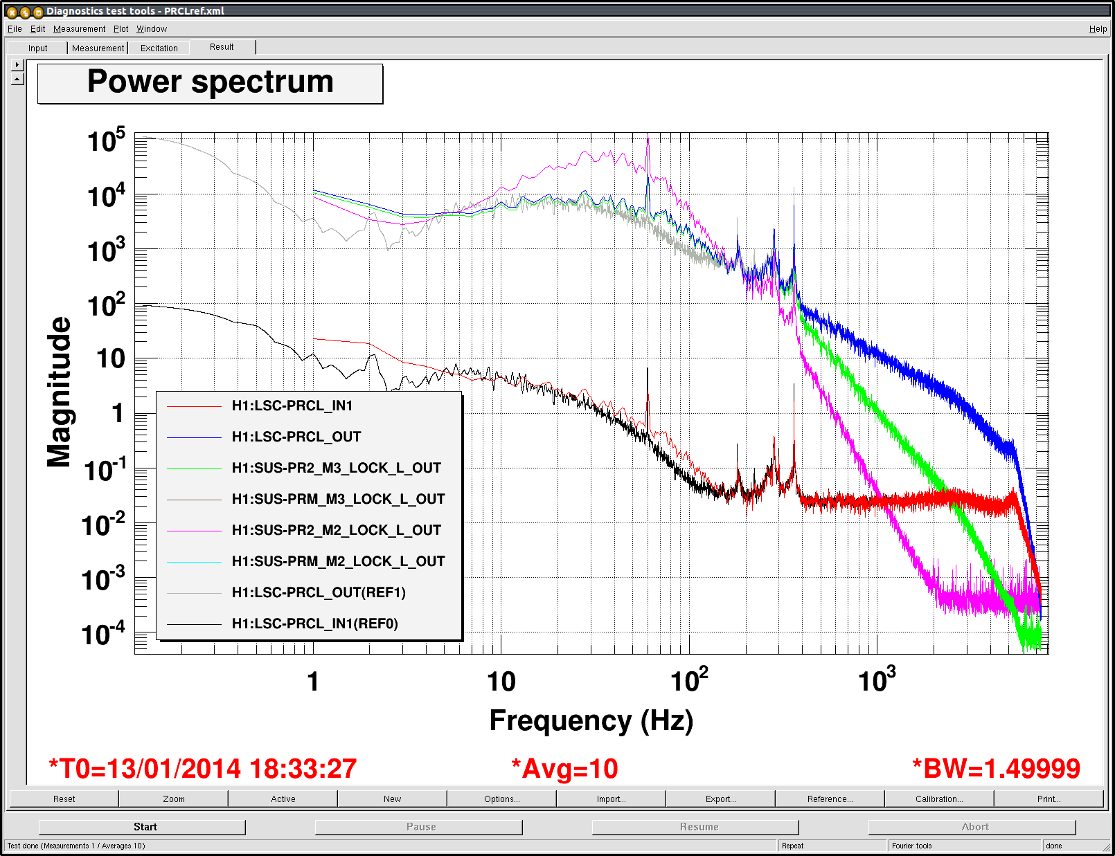
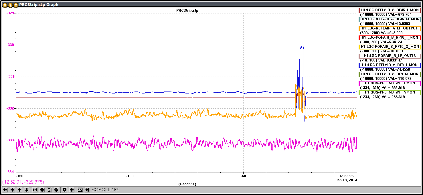
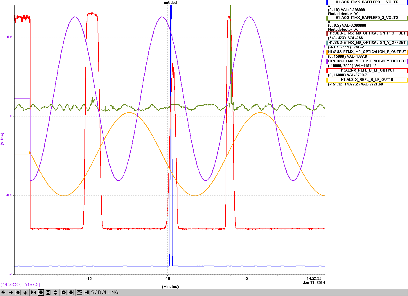
We trended the photodiode signals of the ITMY top osems to verify that nothing is actually physically happening with the LEDs or their light output. No correlation was seen.
Next step is to look at the LED current monitor signals coming from ITMY to see if the signal is dropping out at this very low rate of one second every hour or so.


Here is the last 11 hours of pressure. Looks like the 7kv is doing its thing.