jason.oberling@LIGO.ORG - posted 11:26, Tuesday 10 September 2013 (7699)
ITMx Cartridge Alignment
IAS: J. Oberling
SUS: B. Weaver, T. Sadecki
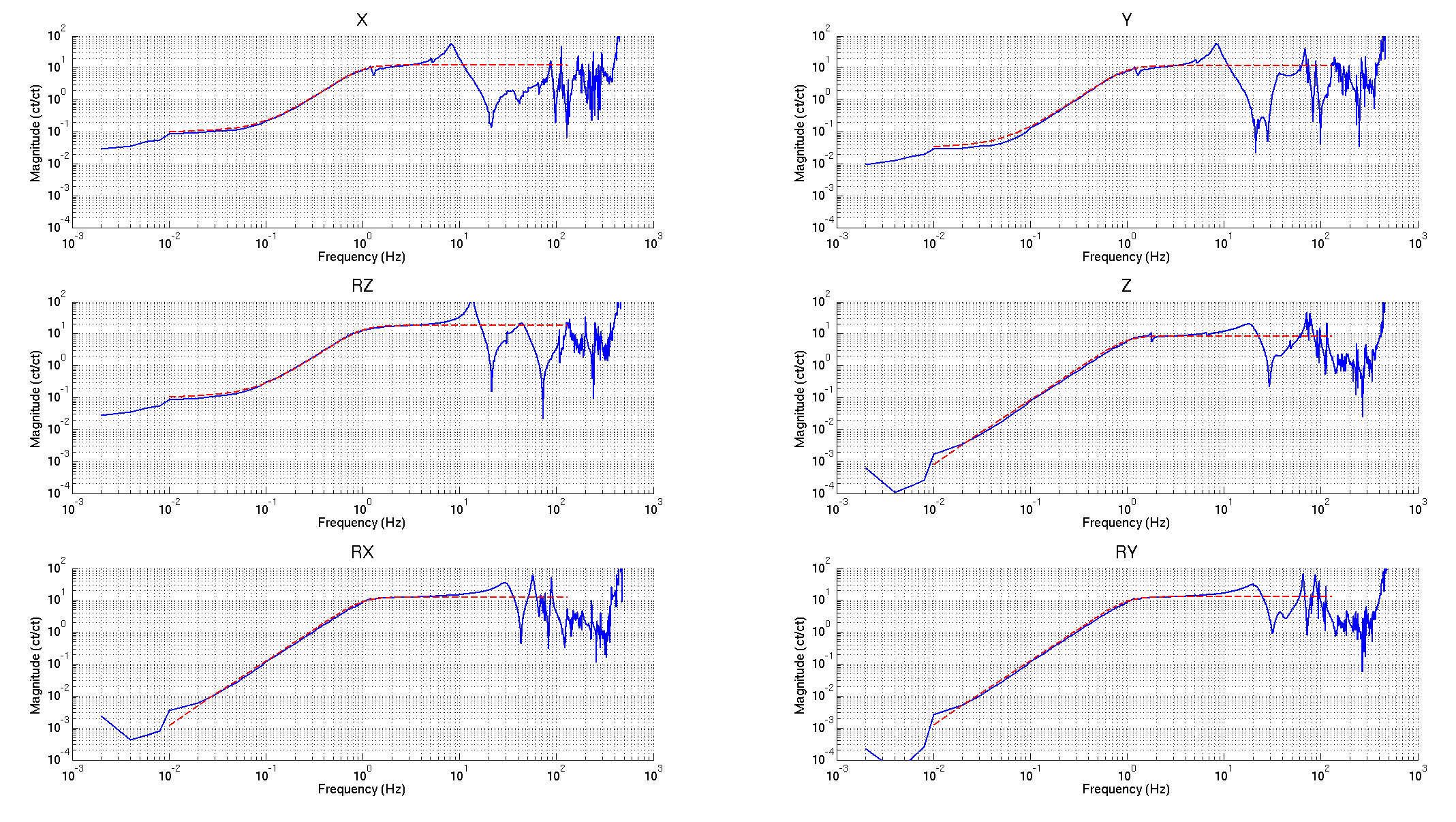
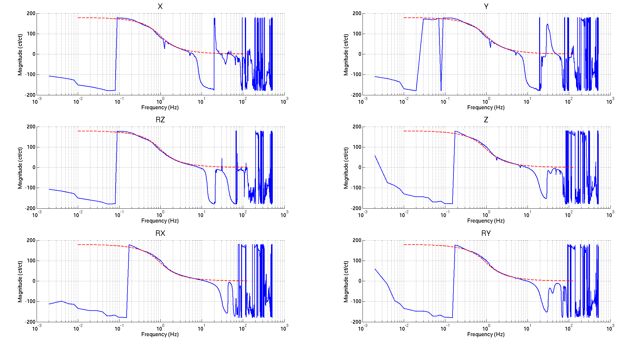
Over the last couple days we've been fighting the CPx alignment. This was "finalized" yesterday until Arnaud's transfer functions showed main chain rubbing (reaction chain good). Travis found and corrected the rubbing this morning and I took another set of pitch/yaw measuremnts of the ITMx to confirm we are still good. We are. The position errors remain unchanged from alog 7638. Pitch/yaw errors and ITMx/CPx gap are as follows:
-
ITMx
-
Pitch Error: 100 µrad up
- Actual Pitch: 519 µrad down
- Target Pitch: 619 µrad down
- Tolerance: ±50 µrad
- This was deemed good enough for the cartridge alignment and will be fine tuned to within tolerance once the cartridge is installed in WBSC3
-
Yaw Error: 30 µrad CCW
- Target Yaw: 0.0 µrad
- Tolerance: ±50 µrad
-
Pitch Error: 100 µrad up
-
CPx
-
Pitch Error: 145 µrad up
- Actual Pitch: 1.255 mrad down
- Target Pitch: 1.4 mrad down
- Tolerance: ±1.4 mrad
-
Yaw Error: 291 µrad CCW
- Target Yaw: 0.0 µrad
- Tolerance: ±1.4 mrad
-
Pitch Error: 145 µrad up
-
ITMx/CPx Gap: 20.33 mm
- Target: 20.0 mm
- Tolerance: ±0.25 mm
- Per Betsy, this is good enough for this pilot ITMx
To be on the safe side, I left the IAS equipment set up at the test stand until we get a good set of transfer funtions.