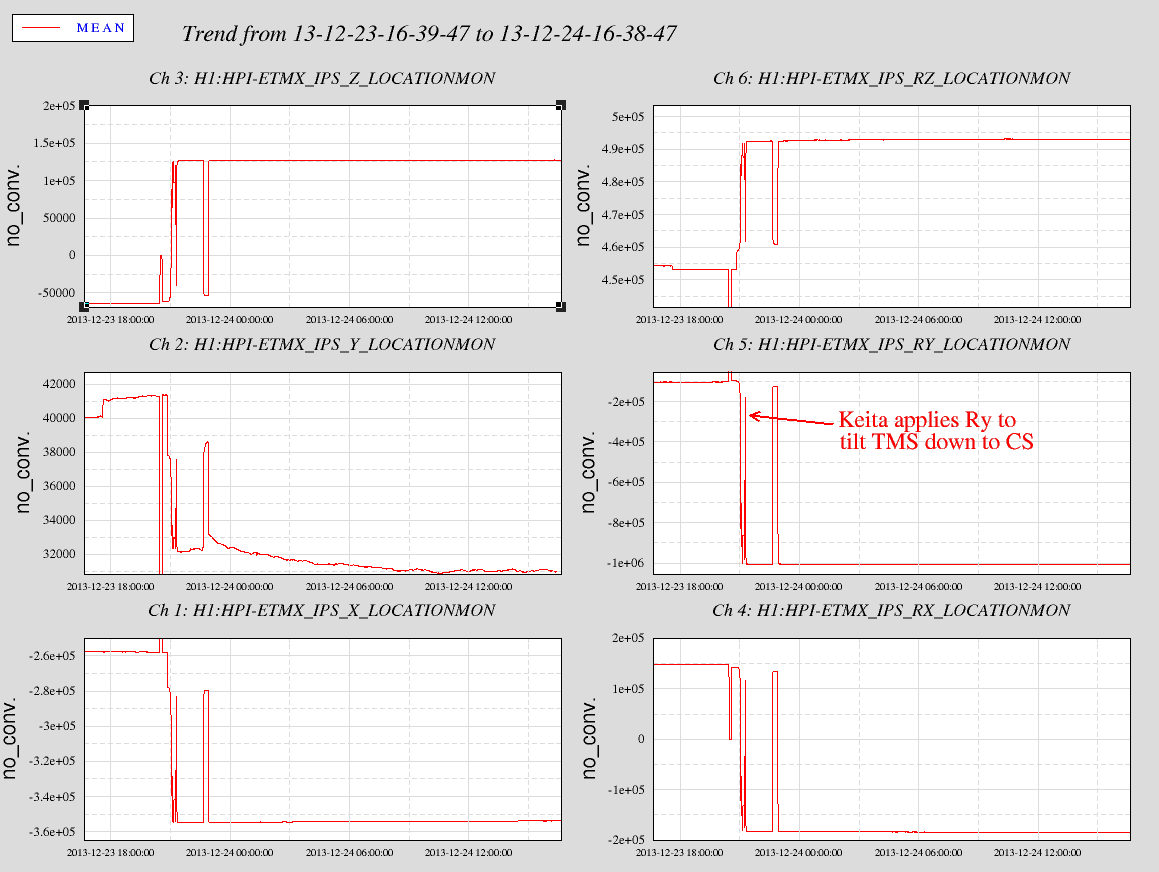
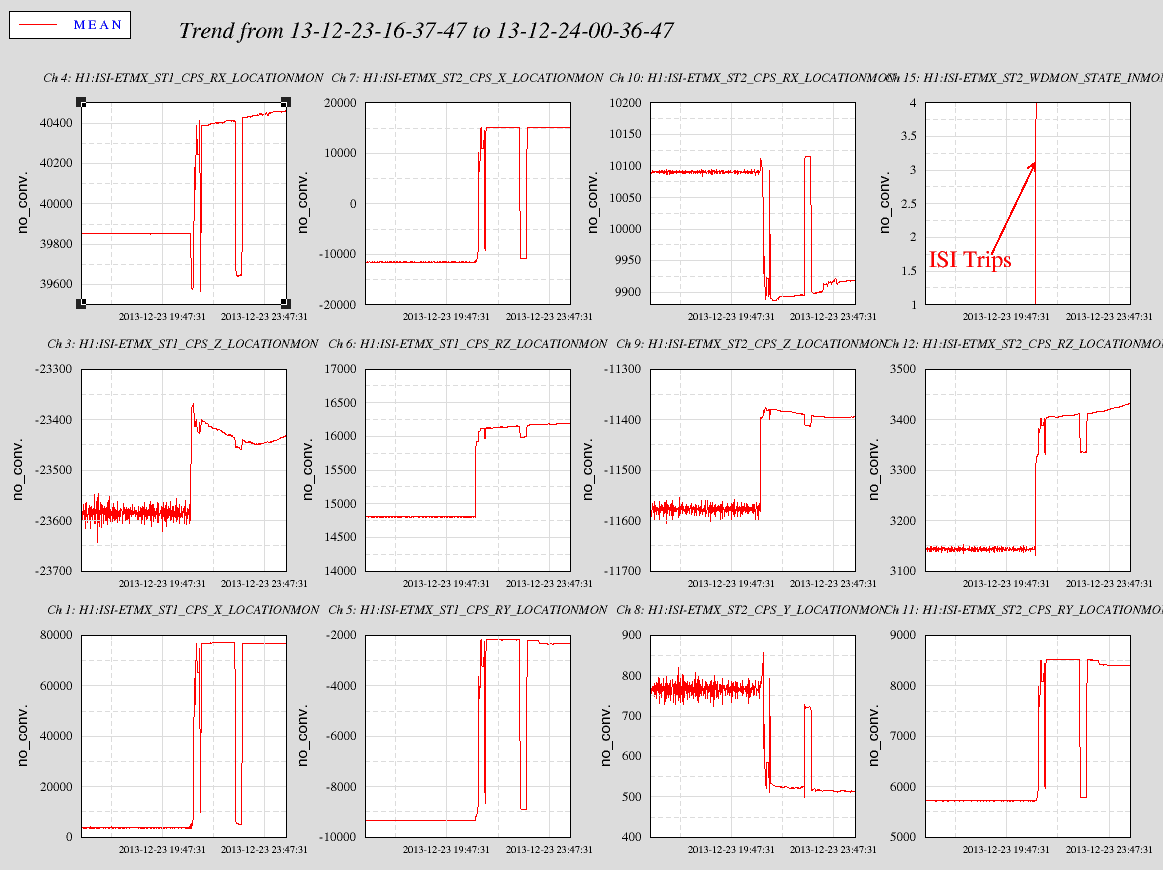
Yesterday Keita tilted the ETMx HEPI in -Ry to pitch the TMS system down to bring the ALS green beam down back at the ITMx. Attached is a plot showing the tilt around 1pm Monday pst. About an hour later, the SUS tripped triggering the ISI and HEPI. We restored the HEPI tilt but did not restore the ISI. It isn't that we forgot but we just didn't think it mattered. However there are DC bias steering offsets on the ISI as well although these are much smaller than the HEPI tilts. The second plot shows the changes in the ISI system with the watchdog tripped.
Couple things--this plot serves as a pretty good record for the steering offsets.
There is pretty significant off diagonal elements from the Ry tilting. Why? Primary is probably the lack of symmetrization filters evenning out the actuator drives. Also, so near the limits of IPS senssing (30/32), the actuators could actually be hitting mechanical stops. The -12000 ct offset in the blend path calcs to a 0.9mrad tilt according to the incorrect IPS2CART matrix. This is actually closer to 0.45mrads but at 2m distance to the Piers, the actuator and IPS are nearly railed. This also gives ~0.17mrads Rx and 10urads Rz corrected. The X Y Z values are correct at .1, .08, & .2um respectively.
Looking at the second plot showing the CPS LocationMons, when the ISI trips and the locations are free to go hang where they may, you see largest motions on Stage1 X, 70um; Stage2 X, 30um and the Ry numbers ~4urads. There are some problems with the CPS matrices too but I think they are mostly sign errors. Anyway it is interesting to see the ISI respond as you'd expect: Tilt the HEPI Ry and see the free hanging ISI tilt Ry and shift X, cool. You might think the ISI would tilt as much as the HEPI but if these numbers are right you'd have to admit they do not. Is that the stiffness of the flexures? How does it impact the Isolation performance?
After Keita aligned ITMX (see 9071), I aligned the corner PRMI using ITMX as a reference. It is flashing now.
Sadly, I still don't see the POP beam either on HAM1 or ISCT1. Also, I looked at the POP penetration hole (swiss cheese baffle) with the camera at HAM3 spool, but no sign of a clipping or scattering was found.
The screenshot below is the current best alignment:
The alignment of the day:
Soft-closed GV7, valved-out IP5, valved-in XBM turbo -> Soft-closed GV20 (ran motor closed for 4 minutes and 16 seconds - until "squeek" of O-rings heard with ear pressed against valve body), valved-out IP12 valved-in X-end turbo
So, ETMx was aligned ~31 Oct, alog 8356. Location monitor channels were not available until ~23 Nov. Attached is a trend graph showing the HEPI IPS signals from the alignment time until the location monitor channels became available. See alog 8504 why the shifts seen are not signifcant.
Second plot attached shows trends of the Location monitor channels to the present. On Dec 5 the HEPI was locked, pump down of the chamber began ~11 Dec and the HEPI was unlocked on the 12th. The lock period is in the middle of the graphs. The lock/unlock times are apparent although pumpdown trends are hidden in the unlock. The shifts in Rx & Ry since the alignment are the most worth noting with 40 to 60urads observed. But don't worry, the input matrix values for these channels are 2x too large so the actual motion is 1/2 this. We'll get those matrix values correct soon! Further, the Rz matrix values is 4x too large so the 30urads recorded is really about 8urads.
So, with these two plots we can track the HEPI position back to alignment. Sorry for not adding the value of telling you where we are now. Not sure how useful that really is since pump down has distorted the floor therefore the piers corrupting the numbers. When we correct the matrix values, I'll have to go through this again as well.
- Kyle, to LVEA, open GV7, and to X-End station, open GV20, see his aLOG.
- Kiwamu, to LVEA, to FIX PSL, working now.
- Jeff and Andres, to LVEA, work by HAM04 area.
- Daniel, to X-End station.
- Sprage was on site today.
- Keita, CR, working with GL, from the X-End to the corner.
In HAM2:
- by changing IM1 alignment, beam on IM2 moved about (0, -1.2mm), (pitch, yaw)
- by changing IM2 alignment, beam on IM3 moved about (-1.1mm, -1.8mm), (pitch, yaw)
- by changing IM3 alignment, beam on IM4 moved about (1.3mm, 0.3mm), (pitch, yaw)
None of these numbers themselves is large enough to be of concern.
In HAM3:
- by changing IM3 alignment, beam on PR2 moved about (20mm, 4mm), (pitch, yaw)
- by changing IM4 alignment, beam on PR2 moved about (0, 18mm), (pitch, yaw)
None of these numbers themselves is large enough to be of concern.
For refference:
The beam at PR2 baffle is about 1000 drive counts in diameter using IM4 yaw. This was measured by looking at the beam as it moved across the vertical frame of the PR2 scraper baffle.
Bottom Line:
IFO REFL was not found, which is a concern, so the IM alignment needs more work.
One concern is that driving the IM2/IM3 combo back to the wall spot may not be the right thing to do (my idea). Inside HAM2/HAM3, the sum total of all of the changes (level, rotation, input beam, etc.) since the spots were made, may make the wall spot invalid.
Doug,Travis, Mark Barton We ran into issues with the fiber profiler. We are unable to get the proper results and ended up with bogus numbers and graphs. Travis emailed Angus who had seen this similar problem before, but wasn't certain of the cause either. We ran 2 different programs and tested them with both new and old data sets yielding the same out come. Mark worked with us later in the day but found nothing obvious either. He will look at the programs, data base and spreadsheets tonight to continue to debugging. Rebooting the computer had its own problems as it took several tries to get it back online. We did manage to tweak the profiler mechanical alignment which allowed us to run continuous passes without having to stop and refocus several times. In conclusion if Mark does not find an obvious problem we will wait until Jan to proceed. The puller is ready, just waiting for the profiler evaluations before the production run. The micrometer is fixed in place and alignment rechecked. I made up several more substrates and cleaned up some more clamp blocks and supports. If Mark finds a fix we may hit it again tomorrow.
For the record, the following are the nominal values used for the large ion pump controllers (listed in the order queried by the MultiVac firmware Flow 7): Torr Spare 7000V 200mA 200watt Protect 10mA STEP 5000V 1.0 x 10⁻³amps 3000V 4.0 x 10⁻⁵amps (StPt 1) 1.0 x 10⁻⁵torr (not used?) (StPt 2) 1.0 x 10⁻⁶torr (not used?) 1.0 x 10⁻¹⁰ 1.7 x 10⁻⁹ 8.0 x 10⁻⁷ 2.0 x 10⁻⁴
Correction: 1 x 10⁻³ amps (should be) 3 x 10⁻³ amps
We soldered together two DB37 adapters to set the gains of the photodiode amplifiers manually. During testing in the corner we noticed that channel 4 was busted. We rewired PD 4 onto channel 3 and left PD 3 out. The transimpedance gain setting in the corner is 20 kOhm and 200 kOhm in the end. Each adapter uses 2 toggle swirtches, labeled D0 and D1, to set the gain:
Andres R & Jeff B After releasing the stops on H1-SR2, we took a series of measurements to confirm the suspension made the trip from the staging building to the LVEA with no problems. The height of the bottom mass is 215.36mm (within tolerance), there is no pitch or roll in the M1, M2, & M3 masses, and the four lower blades are co-plainer with less than 0.5mm difference. We adjusted the BOSEMs for 50% light. Turning on the damping filters showed a sign problem the side BOSEM. Checked the sign conventions in E1100109 and T1200015, and found the side BOSEM sign should be “+”. This was changed in the OSEM2EUL, EUL2OSEM, and Output Coil matrices. All damping filters are now working correctly. Started Phase 2b TFs. Will check the results in the morning.
Summary: Green injection hits the center of ITMX, comes back to the center of ETMX, and then back again to the center of ITMX. The alignment is good, with one caveat that HEPI should be tilted significantly in PIT to help TMS. Since EX PIT is unaffected by the HEPI, we're using EX sus bias to point it down by 330 urad.
1. Green beam from TMSX to ITMY
After Kyle opened the GVs we started scanning TMS to find the green beam on ITMX baffle diodes. Somehow PD4 amplifier was busted so we reconnected PD4 to PD3 amplifier.
At first TMSX was pointing up too much, and I had to give HEPI a PIT (RY) offset of -12000 counts to H1:HPI-ETMX_BLND_IPS_RY_OFFSET with a gain of 1. HEPI loops were all open, so that just gave a DC offset to the HEPI angle. After that treatment, we were able to maximize the output of three baffle diodes using the following offsets for TMS bias:
| Center =(PD1+PD4)/2 | PD1 | PD2 | PD4 | |
| H1:SUS-TMSX_M1_OPTICALIGN_P_OFFSET | 152.5 | 118 | 53 | 187 |
| H1:SUS-TMSX_M1_OPTICALIGN_Y_OFFSET | -221.5 | -190 | -256 | -253 |
See E1300634, figures 12 and 13, for the diode layout. PD1 and PD4 are two diagonal ones around the baffle hole, PD2 and PD3 are far from the mirror. "Center" is the mean of PD1 and PD4 and should be close to the real center of the optic.
Baffle diode channel names are H1:AOS-ITMX_BAFFLEPD_1_POWER etc., but they are not trended as of now. Also note that H1:AOS-ITMX_BAFFLEPD_3_POWER is actually reading PD4.
Transimpedance for the PDs were set to 20 kOhm, and when maximized the outputs were about 2.5V for PD2 and PD3, and about 2.3V for PD1.
2: ITMX reflection on ETMX
Got the beam reflected off of ITMX on ETMX baffle diodes. We used a factor of 10 larger trans impedance (200kOhm). All diodes worked and the channel numbering made sense. H1:AOS-ETMX_BAFFLEPD_1_POWER= ETMX baffle PD1 etc.
| Center | PD1 | PD2 | PD3 | PD4 | |
| H1:SUS-ITMX_M0_OPTICALIGN_P_OFFSET | 82.8 | 66.6 | 36 | 65.6 | 99 |
| H1:SUS-ITMX_M0_OPTICALIGN_Y_OFFSET | -55.5 | -72.9 | -41 | -8.9 | -38 |
Despite 10x higher trans impedance the maximum we got was something like 6V (VS 2.5V), so it's like a factor of 4 reduction. Probably the mode matching into the arm is not good.
3: ETMX reflection back to ITMX
I had to tilt the ETMX significantly in PIT, but anyway.
| Center | PD1 | PD2 | PD4 | |
| H1:SUS-ETMX_M0_OPTICALIGN_P_OFFSET | 332.5 |
310 |
290 | 355 |
| H1:SUS-ETMX_M0_OPTICALIGN_Y_OFFSET |
-3.75 |
26.5 | -10 | -34 |
Transimpedance is again 20kOhm and the maximum was about 0.3V, so it's a factor of 2 reduction in power (VS 6V 200kOhm ETM diodes).
At this point I had a power back in REFL B diode, and saw a fringing, but after 5 minutes the fringing was gone. Either the alignment is drifting (turns out that the ISI was undamped), or the frequency noise is too large (couldn't lock PLL).
During this operation I tripped ETMX watchdog, HEPI was restored after that but I forgot about ISI. That is OK, it's just that ISI was undamped.
4. ETMX initial alignment implication
The above shows clearly that, without any suspension slider bias, ETMX is pointing up 330 urad.
This should be either the initial alignment (we dead reckoned 300 urad caused by the weight of first contact) or the optic drifted after pumping down, but the former is more likely.
There's an update entry:
https://alog.ligo-wa.caltech.edu/aLOG/index.php?callRep=9126
JimW GregG Hugh
No issues to report here. Jim got non-plated screws for screwing into the aluminum and this helped things go smoothly. Couple photos attached--lots of space available still!
As a preparation for the PSL power increment, a mid-high power beam dump, Kentek ABD-2NP, was installed in the IMC REFL path on IOT2L. It is in the location of IO_MCR_BD1 (see the layout D0902284-v9). This dump is capable of 50 W.
Burped GV7's gate annulus volume into annulus ion pump only instead of pump cart-only minor bump in ion pump current -> valved-out XBM turbo -> opened GV7 -> Burped GV20's gate annulus volume into pump cart - pegged ion pump current briefly -> Valved-out pump cart and verified that ion pump could handle gas load with gate annulus valved into ion pump -> closed gate annulus isolation valve -> Disconnected pump cart from annulus plumbing -> Valved-out X-end turbo -> Opened GV20
PSL was found to be down this morning. The interlock was triggered on Dec. 22nd at 17:26-ish PT. Most likely due to an error in the water flow meters.
I restarted it. PSL is now back up and running.
The X end PLL is locked.
The laser settings are: 1.842 Amps and 31.77 C, with these settings the temperature can be adjusted to move the beat note +/- 400MHz with no evidence of mode hopping.
The gain settings are -8 for fast gain, -4 for common gain, giving a ugf of 13.6kHz (open loop gain first photo). I first locked with a fast gain of -5, commong gain -4, ugf 17kHz, but this resulted in some oscillations at 200kHz, shown in the second attached photo. these are gone with the lower ugf, 3rd photo.
The frequency comparator is not working well, for now we can lock using the ceiling camera to look at the spectrum analyzer, but not the autolocker which relies on the readback of the beat note frequency. This readback is OK when the loop is locked, but not verry usefull otherwise. The problem is probably that we are sending 20dBm into the timing comparator for the VCO readbacks, and our signal is more like -30dBm on the adjascent channel. We encountered this problem at end Y and fixed it by adding attenuators. I gues that we need to add the final solution to the issue tracker so livingston doesn't have the same prolem.