sheila.dwyer@LIGO.ORG - posted 17:30, Tuesday 14 January 2014 (9280)
End X activity done for the day
Keita, Alexa and I have returned from end X
Keita, Alexa and I have returned from end X
Added an offset zeroing script for QPDs to the svn: asc/common/scripts/setQPDoffsets (SVN revision 6861).
It uses tdsavg to set the four segments to zero, and sets an offset of 4 counts into the sum filter module to avoid a division by zero.
Preconditions: no light on diodes, segment gains have to be -1
Tumbleweed bailing on X arm
10:07 - 10:28 Apollo moving contents of garbing room from West bay to HAM4 (by hand) (WP 4393)
10:54 Site water sample collecting
11:30 Lightning rod work
13:29 Sheila working at end X
12:51 DAQ restart, new channel list for H1EDCU_ECATX1PLC3.ini for Thomas' ring heater changes.
I modified the mod_ini scripts to arrange channels in alphabetical order so we actually got new H1EDCU_ECATXXPLCX.ini files for all systems (new channel order) but only H1EDCU_ECATX1PLC3.ini had new/removed channels.
New ini files committed to svn, version 6859.
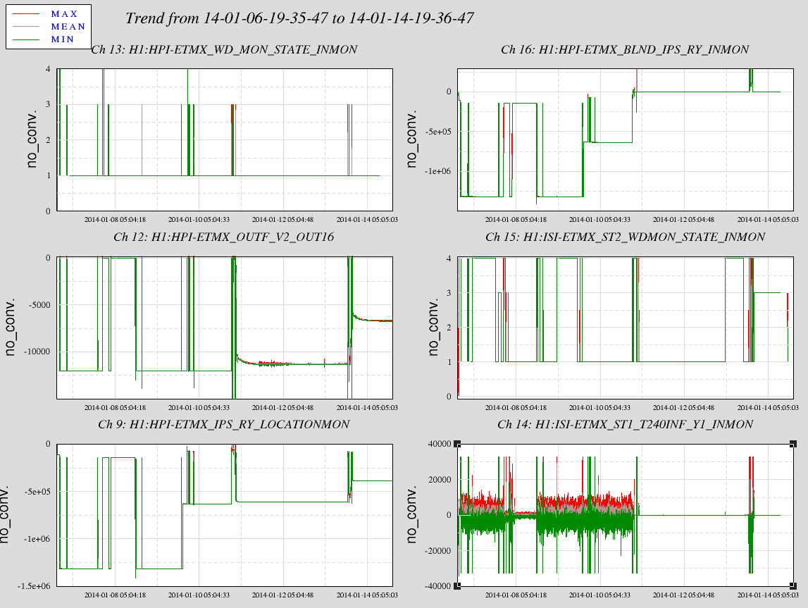
The large tilt requirement into HEPI for the TMS tilting really accentuated the IPS sensor noise when the HEPI loop was open. The HEPI had not been commissioned so the tilt was direct drive. On Friday Jim, Fabrice and I closed those loops and I did my best to restore the previous tilt to the system. We only got to within ~25urads cause the other loop closings caused more drive to the the V1 corner pushing the IPS to 29900counts with a watchdog trigger at 30000.
See the attached 8 day plot. The plot shows lots of things but mainly look at the lower right graph with T240 INMON. The first half of the plot is before the hepi position loops were closed. The quieter interval in the middle left, was during a noise study and we had no tilt (see the various hepi graphs). In the middle of the time frame we closed the ETMX HEPI position loops and you see the T240 channel go very quiet. There are no railing spikes that would have tripped the ISI. On Monday, Keita offloaded much of the HEPI tilt to the TMS because the HEPI IPS was close to its trip level and TMS needed a little bit more tilt. You can see the HEPI tilt change in the channel 9 & 12 graphs. However, there is no change in the noise at the T240 when Keita offloaded HEPI to TMS (I zoomed in and there is no difference in the time series view.)
Bottom line, The HEPI tilt will not cause ISI trips with the HEPI position loops closed. HEPI could take much of the TMS tilt back if needed.
See 9317--apparrantly not so uch, ah well.
Wrote and installed the code for running the ring heaters.
Added the rough calibration values that Aidan B had recommended for running the ring heaters.

Some data below:
Upper:
Requested Power = 1.00 Watts
Requested Current = .17 Amps
Measured Voltage = 6.85 Volts
Measured Current = 0.16 Amps
Calculated Power = 1.13 Watts
Calculated Resistance = 42.81 Ohms

Lower:
Requested Power = 1.00 Watts
Requested Current = 0.17 Amps
Measured Voltage = 6.71 Volts
Measured Current = 0.17 Amps
Calculated Power = 1.11 Watts
Calculated Resistance = 39.47 Ohms

A quick, back-of-the-envelope calculation shows that the ring heaters are working properly. Although their values are a bit different than ITMY shown in ALOG 8816, this is mostly due to only being roughly calibrated.  The next step is to do a long term 4+ hour test to show curvature change and robustness.
10:51 I restarted the h1slow-cds epics gateway due to Beckhoff IOC work.
Done
Done
Done
Breaking for lunch
All models have stopped on h1seih45 at 1073754093, having suffered an ADC timeout. It's possible that the timing fiber was disconnected for work, not sure of the cause. I am going to reboot the computer after removing it from the dolphin network.
Computer rebooted, all models are running.
This was necessary because the model stopped running when I swapped ADC 1 and 2 ribbon cables in the IO chassis.
(Alexa, Daniel, Sheila)
PLL Beatnote:
PLL Open Loop Transfer Function:
PLL Noise Spectrum -- via IMON of PFD (S1000758)
PLL Servo Board Transfer Function:
Shot Noise of PLL BBPD:
The missing SR785 measurement:
PLL Open Loop Transfer Function:
Input 1 pol: NEG, Common Compensation: ON, Generic Filter: ON, Fast Option: ON, Fast Gain: -8dB, Input 1 Gain: 0db, Boost 1:ON rest OFF
   Last set of TFs on H1-SR2 showed a longitudinal to yaw cross coupling at 1.51 and 2.77Hz. I adjusted the Coil Holder and recentered the BOSEMs.

   There were only two of the four Coil Holder Mounting Brackets installed, (which may be a source of the noise in this suspension and a contributor to the cross coupling) when the earlier TFs were taken. The missing two Mounting Brackets required modification due to misaligned mounting slots. These modifications were not completed in time to be installed on the suspension before it was moved to the LVEA. One of the Mounting Brackets was modified correctly; and has been installed on the suspension. The second Mounting Bracket was not modified correctly and will need to be reworked before it can be installed. Three of the four Mounting Brackets are now clamping the Coil Holder to the Weldment.

   I have started a new set of TFs on H1-SR2, to see if the BOSEM adjustment and the addition of the third Mounting Bracket will improve the performance of the suspension over that revealed in the earlier TFs.
For my own apparent nomenclature, the "coil mount brackets" that Jeff is referring to is actually the tablecloth mounting brackets which attach it to the structure.

