[Jim, Sebastien]
As we discussed during the SEI meeting today, we noticed 3 main issues on the BSC-ISI ITMX transfer functions taken by Hugo and Jim last week (https://dcc.ligo.org/DocDB/0070/E1100848/007/ITMX_TF__2013_11_19-2.pdf).
Extra resonances around 2Hz (fixed)
Two extra resonances at 2.05Hz and 2.275Hz appeared on the ST1 main transfer functions (CPSs, L4Cs and T240s). Since it shows up only on Stage1, it must be coming from the arm cavity baffle installed on Stage 0. We locked/unlocked the baffle to see if it makes any difference.
The measurement showed in the first plot were taken using DTT and a white noise excitation.
As you can see, after locking the baffle the first time, the issue seems to be gone! Our theory is that the eddy current damping wasn't working properly on the baffle. By locking and unlocking it, we changed it in some way to make it better. To comfirm that theory, the next step would be to remove the copper block from the baflle and see what happens on the ISI.
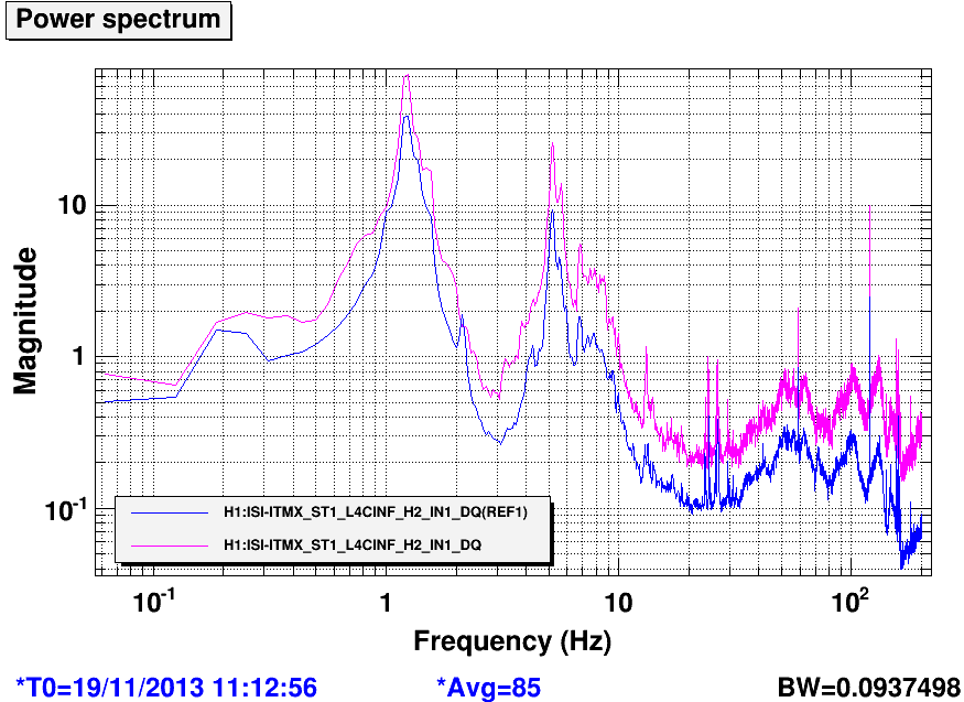
Low gain on L4C-H2 (fixed)
L4C-H2 gain was down by a factor of 2. We first though of a bad connection somewhere, preventing to have a real differential signal. After we "played around" (swaping cables, checking cables and screws), it seems to fix itself (!! see plot attached). The blue curve is the ASD before the "fix", the purple one is after.
We don't really know what action we did to make it happened, and how to reproduce the situation.
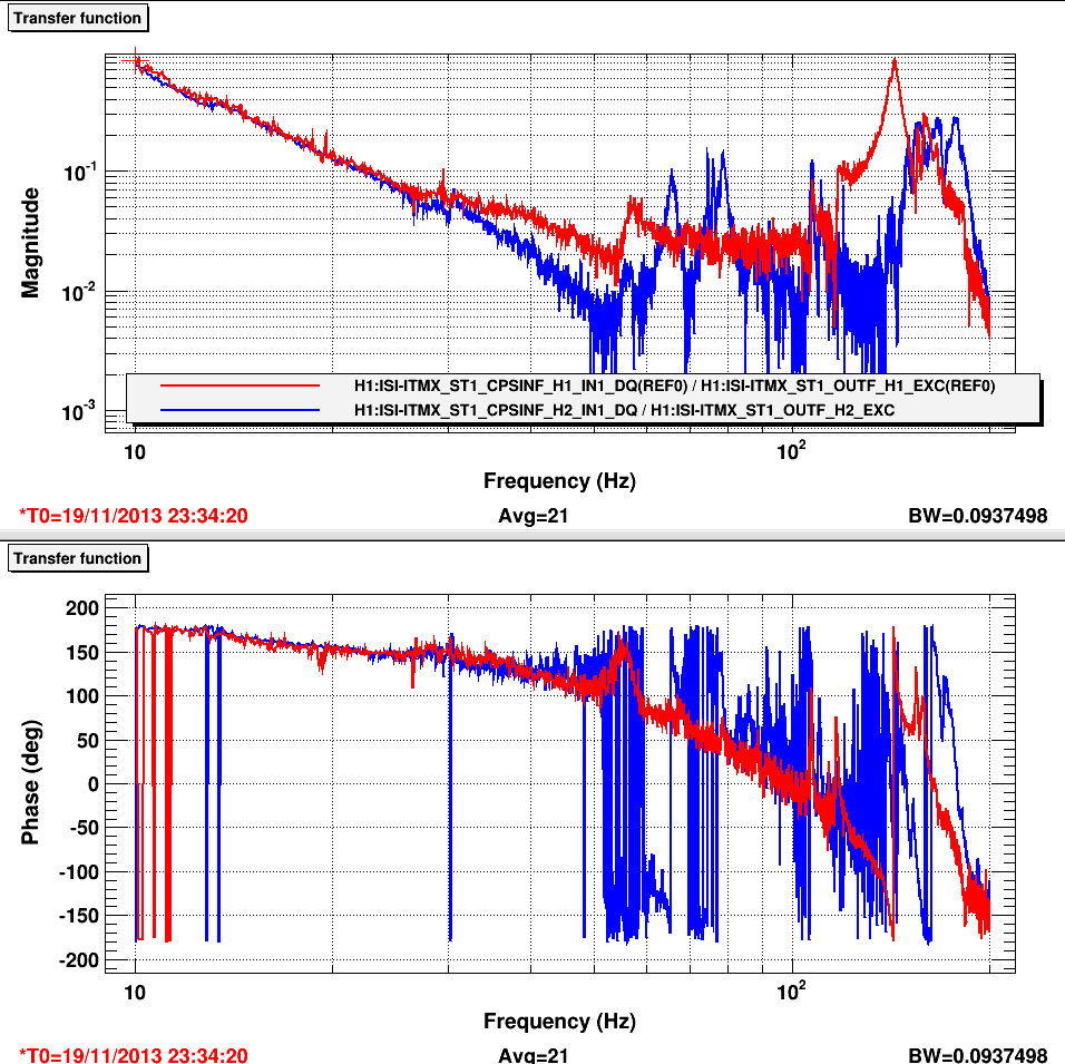
ST1-CPS-H1 high amplitude at high frequencies (not fixed yet)
The ST1-CPS-H1 main transfer function shows an unusual high amplitude level above 25Hz. We first though that something was loose, but Jim inspected everything and couldn't find anything wrong. We'll investigate more tomorrow (CPS grounding issue???)
This quick and confusing analysis is a first result and need more data to be confirmed. A full set of transfer functions will be take tonight.


Filiberto changed the satellite box and the signals are now alive.