Alexa, Sheila, Kiwamu
The goal of the day was to get the retro-reflection from PRM all the way back to PSL. And this was achieved. We are ready for the HAM1 incursion.
This work involved:
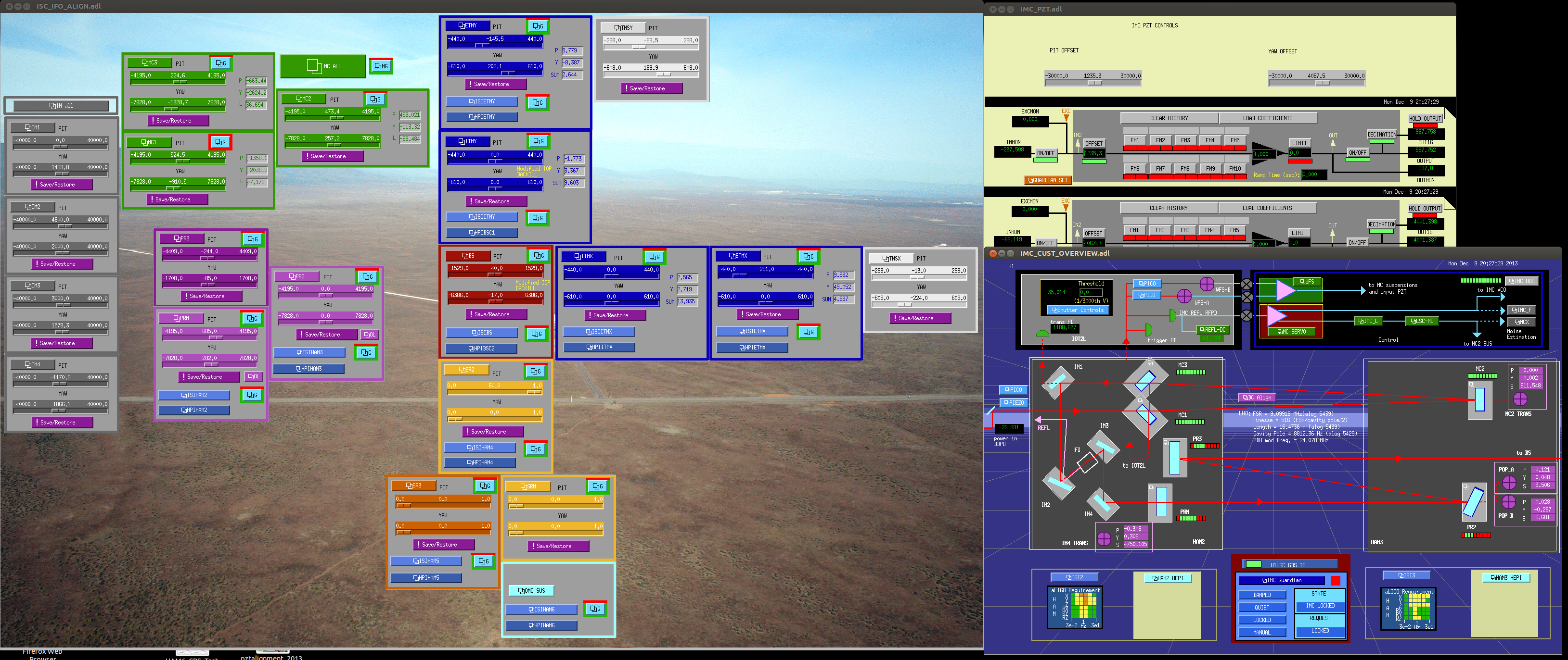
- Restoration of the IMC alignment back to that established in this past Friday.
- Re-engagement of the ASC loops on IMC.
- Checking the Faraday clearance by looking at scattering light around the waveplate baffle at the entrance of the Faraday,
- Adjustment of the alignment of IM1 and 2 to get through the Faraday.
- Adjustment of the alignment of IM2 and IM3 to get the same spot position (a.k.a. IM4 trans) marked on the wall.
- Adjustment of the alignment of IM4 to get the same spot position (a.k.a. return beam) marked on the wall.
-
Adjustment of the alignment of PRM to get the retro-reflection all the way back to PSL.
- For getting the retro-reflection, we used the beam splitters that Paul installed for his Faraday loss measurement.
- The PD for this retro-reflected light is now connected to the SPARE_10 lemo cable, so that one can see the signal at the outside.
In the process of aligning PRM, we looked at the in-vac WFS in HAM1 with a viewer and saw the reflection light hitting the WFSs. We didn't check the beam on the WFSs after obtaining the retro-reflection, but they should be pretty close to the good alignment. Then after obtaining the retroreflectin, we went to ISCT1 to see if we get some light on the table, but we didn't find it. Maybe it is blocked by an optic for some reason as we can see scattered light. So the first thing we should do before the incursion is to check the beam alignment in HAM1 and see if makes sense. It might be possible that the alignment in HAM1 is bad even though we have a retro-reflection back to PSL. In this case, we should steer IM1 and IM2 to change the rejection angle of the REFL beam while keeping the retro-reflection.
P.S. We left PSL in the commissioning mode. The IMC autolocker is running on opsws3. The attached is the alignment that we established. I tried steering the IM4 trans picomotor, but it seemed not moving at all.