kyle.ryan@LIGO.ORG - posted 18:18, Tuesday 26 November 2013 (8755)
Soft-cycled GV19 for Apollo to connect spool to GV20
Kyle
Kyle
Gerardo

Replacing (4) each OE check valves
Added a line to source the epics-user-env.sh file for the proper version of epics in the burt backup scripts running on script0. The environment was incorrect and the burt backup was failing.
Here is the current status of the aLIGO SEI work at Hanford. The main updates of this week are:
- ITMX, HAM2 and HAM3 have been tested (chambers are closed)
- HEPI generic and local models have been updated, installed and tested
· BSC1 - ITMY
o ISI + HEPI - Unlocked, Previously commissioned.
· BSC2 - BS
o ISI + HEPI - Unlocked, Previously commissioned.
· BSC3 - ITMX
o ISI : Testing complete, in chamber. Report validated.
o HEPI : Unlocked.
· BSC9 - ETMX
o ISI : Unlocked. Testing complete.
o HEPI : Unlocked, ongoing initial alignment.
· BSC10 - ETMY
o ISI : Currently installed in BSC6. Will be pulled out and installed in BSC10. Payload (SUS) will be moved then. Electronics are disconnected
o HEPI : Unlocked.
HAM 1
o HEPI: Locked and vented.
Low priority testing
· HAM2
o ISI: previously commissioned with HEPI locked, currently unlocked, in vacuum
o HEPI - IPS position loops and alignment offsets installed
Locked
· HAM 3
o ISI: previously commissioned with HEPI locked, currently unlocked, in vacuum
o HEPI - IPS position loops and alignment offsets installed
Unlocked
· HAM 4
o ISI: In chamber, Previously tested during assembly validation, currently locked, no suspension installed, in-vac cables not connected.
Electronics ready, in field cables ready, in-rack cables ready. Temporary STS cables
Model is running, and MEDM screens are available in the Sitemap.
o HEPI: Currently locked, to be commissioned
Electronics ready, in field cables ready, in-rack cables ready. Temporary STS cables
Model is running, and MEDM screens are available in the Sitemap.
· HAM 5
o ISI: In Chamber, Previously tested during assembly validation, currently locked, no suspension installed, in-vac cables not connected,
Chamber temporarily closed.
Electronics ready, in field cables ready, in-rack cables ready. Temporary STS cables
Model is running, and MEDM screens are available in the Sitemap.
o HEPI: Currently locked, to be commissioned
Electronics ready, in field cables ready, in-rack cables ready. Temporary STS cables
Model is running, and MEDM screens are available in the Sitemap.
· HAM 6
o ISI:
in chamber.
Unlocked, no SUS
Mechanical adjustments complete
Initial in-chamber testing complete, but not validated yet
o HEPI: Locked
This falls under WP 4303.

The dust monitor code tested under WP 4287 survived the weekend. The difference seems to be running it with 'procServ' instead of 'screen'.

I made tagged releases of the tested code and updated the target directories in /ligo/lho/h0/target. The support module was tagged as met_one_227b_comp_ctrl-1.2.0 and the IOC directory was tagged as dust_met_one_227b_comp_ctrl-1.2.0. I changed the startup scripts in the target directories to use 'procServ'.

I restarted the IOCs from the target directories on h0epics.
- EX feadthrough work
- dust monitor code change
- close GV19
- install spool X in LVEA
- reinstall cryopump EX
- test stand reinstall/level EY
- X arm spool oplev piers - drilled anchor bolts
- replace SUS and ISC HAM-A coil drivers, which are actually IO optics
- pull cables HAM6 to electronics room
Coil drivers were changed for IM1, IM2, IM3, IM4, and all offsets required changes. This was complicated by choosing to do this change on the day we started pumping down the vertex, i.e. optics are moving due to pumpdown - choose comparisson times wisely. Spreadsheet attached shows times used and old and new offsets.
Reset OSEMINF offsets to old values - changed alignment drives to recover optic positions, but we are saturating because the reduction in driver strangth is too much, and IM3 is still 300urad from it's aligned position - not good, won't work.
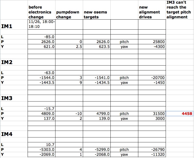
For more details, see LHO aLOG 8767.
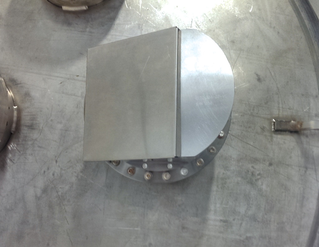
Tyler G. Greg G.
Fabbed up some sheet metal covers for the BSC 1 and 3 viewports. These were installed to make the viewports compliant with our laser safe standards. They don't have warning labels on them saying not to be removed, so try and avoid removing them.
J. Kissel

I've gathered full sets of close out transfer functions for H1SUSPR3 (and HLTS) and H1SUSITMX (a wire-suspended QUAD). The results look good enough to proceed with pump down!

Yellow Flags:
H1SUSPR3 -- The Q of the 1st first vertical mode appears to be reduced from previous measurements of the free in-air suspension. I attach the .pdf of the raw DTT results for this DOF as well, to show that the coherence is still good for this resonance, implying a real loss mechanism. This is also noticeable on the R and T degrees of freedom as well, again only on the first resonance. But all resonant frequencies are in the same place, so the dynamics are as expected and well-behaved. In the end, we want these modes damped anyways, right? However if it is a real source of loss, then it's a source of noise. However, given that these are all the lowest frequency resonance, and it's the V/R DOFs it means that the loss is most likely on the top blade springs -- well away from the optic, so what ever excess noise is present will be filtered by the otherwise free SUS.

H1SUSITMX -- The only thing awry here is that the R0 V and R DOFs show much higher response (an overall DC scale factor) than expected. However, it was immediately obvious that this is a result of calibration filters not turned on. Taking a look, we immediately discovered this to be the case -- the "to_um" filters has been turned off for ONLY the R0 LF and RT OSEMs. They're now turned on, and we will be sure to capture a new safe.snap so this problem doesn't arise again.


All data and common scripts (with updated meas:ists) are committed to the SusSVN as of this entry.
Sorry - that was my bad - I turned these 2 filters off in order to test before shutting the doors and did not get them turned back on.
Tested the cables at the Sat. Amp connector to Ground.  Verifying Pin 13
Was attached to Shield then Pin 13 to Ground.
H1:SUS_ETMX-1 PASSED
H1:SUS_ETMX-4 PASSED
H1:SUS_ETMX-7 PASSED
H1:SUS_ETMX-16 PASSED
H1:SUS_ETMX-19 PASSED
H1:SUS_TMON-1 Failed.  Showed short to ground somewhere between Sat Amp and OSEM.
H1:SUS_TMON-4 PASSED
Hugh Radkins and Richard M

Tested the ETM-X ESC cable.  Hugh was kind enough to work inside the chamber while I checked the connection from outside.  ON first inspection 3 out of the 5 pins were making contact.  Hugh removed the connector then reseated it rocking it back and forth as he inserted it.  This seemed to work.  He then tightened the connection alternating between screws until the unit was tight.  I retested all of the pins and we have connection through the system.
h1oaf0 was powered down to add a additional ADC and DAC to the IO Chassis. The computer remains down for now due to the EY systems being offline
At EY, h1susey, h1seiey and h1iscey are down to rearrange the cards in their IO Chassis to match the EX configuration.
Patrick, Kiwamu
This is a follow-up work of the PSL power control rotation stage (see #8606). The punch line is that:
This morning, we installed a +/- 24V power supply cable to enable the relay circuits for the interlock. This power cable connects the interface box, which is currently sitting on the PSL table next to the periscope (see #8606), and a LIGO-standard power strip underneath the PSL table. I confirmed that it lighted up an LED on the front panel of the interface box. Then I connected the two-pin motor power and DB15 cables at the Beckoff chasis which had been disconnected 10 days ago (see #8593) for a safety purpose. To plug them back in, I powered off the chasis for approximately a minute. Then, I powered it up again after I plugged them.
We tested the rotation stage to see if it is functional. At the beginning, because the interlock was at the disable position (the mechanical switch was in its down position), the rotation stage didn't move at all regardless of what kind of command I sent. This is good as this is how it is supposed to be. Then we switched the interlock to the enable position by toggling the switch. This then allowed the rotation stage to move. So it is working fine and ready to go.
Note that, at the moment, the rotational stage doesn't have a waveplate in it. Plus, the stage is sitting aside the main path, so it is not going to do anything for the main beam.
PLEASE NOTE THAT IT IS NOT CLEARED TO BE PUT IN THE LASER PATH.
I have been working on using the lower stage sensors (L1 and L2 OSEMs together with optical levers) to get information about the longitudinal displacement of each test mass of a quadruple suspension. I have been experimenting with trying to match up yaw signals on the quad because this degree of freedom is relatively uncoupled, unlike pitch or longitudinal. The results are somewhat promising, except for an unexplained factor of ~10 difference between the OSEMs and optical lever data. More information can be found in this report on the DCC:
https://dcc.ligo.org/LIGO-T1300957
The matlab code that was used to generate plots in that document is
/ligo/svncommon/SusSVN/sus/trunk/QUAD/Common/MatlabTools/QuadModel_Production/Diagnostic_sensors/generate_damped_yaw_models.m
I will be taking doing maintenance on the LHO aLOG today at 12:15pm
Pacific.

Please have all entries posted to the logbook or saved to a draft before
12:15pm.

It will NOT be safe to work on an entry after that point until I have
sent an all clear notification (which will include a comment on this aLOG entry).

If everything goes smoothly the aLOG will go through a few phases:

* total outage (a few minutes)
* read only while the system is being verified
* back to normal use

The work will not extend the functionality of the aLOG.  It is a
operating system upgrade and a relocation which will be a step towards
making the LHO computer users room an overflow for the control room.
The upgrade is complete. This comment is to verify that the L-mail works.
Maintenance is largely done.  There is one outstanding issue, the L-Mail notifications are no longer working.

Feel free to use the aLOG, but note, the mail notifications may not be working.
Mail notifications are working. The aLOG maintenance is complete.

Corrections to Status as of 26 Nov:
BSC9--ISI is Locked
BSC10--HEPI is locked (No Payload)
HAM6--ISI Locked