patrick.thomas@LIGO.ORG - posted 09:21, Monday 18 November 2013 (8600)
Restarted IOC for dust monitor at end Y
It appears to have crashed over the weekend.
It appears to have crashed over the weekend.
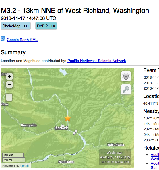
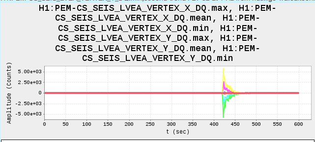
There was an earthquake close by this morning at 06:47. SUS IOP watchdogs did not trip, looks like it was all over in less than a minute.
The plot is 10 minutes of second trends, starting at 06:40.
Changed the /opt/rtcds/userapps/etc/userapps-user-env.sh file to a new copy checked out from the userapps repository. The new configuration includes paths added to support the userapps repository changes made Nov. 15.
Changed the /opt/rtcds/userapps/etc/userapps-user-env.sh file to a new copy checked out from the userapps repository. The new configuration includes paths added to support the userapps repository changes made Nov. 15.
[Jeff B, Jeff L, Rich A, Koji A]
On Friday, we looked at OMCS for the preparation of the installtion after the TF approval in the late afternoon.
- Dog clamps, 12pt screws, the cookie cutter, and its screws were prepared.
- The genie lift was moved near HAM6
- We looked at the cable routing. The quadrapus cables are too long & we have three unused connectors.
They will be tacked on the OMCS structure.
- The isolation between the cable shields and the suspension structure was checked. We found that the
shield of the OMC ISC cables are shorted to the suspension structure. The DCPD preamp housings
(made of AL) are directly attached on the structure. (The situation is the same for the LLO OMC too.)
We can't isolate the preamp right now unless we have some special PEEK components
such as PEEK 1/4-20 screws or PEEK shoulder washers for 1/4-20. We have CLASS A, C&Bed Kapton
sheets, which may be useful.
On Monday morning, we continue to work on the cable routing while the remedy for the preamp isolation will also be explored.
With help from CherylV, JoeG, VolkerQ, OlliP, PeterK et al., we completed the installation of the H1 PSL ISS 2nd loop PD array in HAM2 yesterday afternoon.

This array was fabricated and aligned by OlliP, PeterK, RichA, and CalumT at CIT, then shipped to LHO and set up in the H2 laser area enclosure for further testing of sensitivity to pointing fluctuations and final alignment.

An updated method for quantifying the pointing sensitivity and executing the final alignment was developed and is documented in T1300925 which will be posted to the DCC shortly.  Also, the performance of this array is captured in the test report, E1300863, which should also be posted to the DCC shortly.

The installation went relatively smoothly after recovering from compiling issues after the update of the RCG code on Tuesday (thanks to Arnaud and Jeff for help with the suspensions).  The DC voltage levels seem to indicate that the PD positioning was somewhat compromised compared with what was achieved in the H2 Laser Area Enclosure before transporting, installing and connecting cables.  I suspect that the forces involved in connecting the cables and the weight of the cables is responsible for movement of some of the PDs.

All eight array PDs and the QPD checked out electrically and with laser or flashlight light.

The measured DC levels after installation and alignment (viewed from the back - terminal side of PDs) were:
Upper Left:   415 mV
Upper Middle Left: 475 mV
Upper Middle Right: 470 mV
Upper Right: 365 mV
Lower Left: 395 mV
Lower Middle Left: 67 mV
Lower Middle Right: 565 mV
Lower Right: 554 mV

Pre-installation measurements are summarized in the attached plots.
Alexa, Rich

Detectors ASC_AS-A and ASC_AS-B have been installed and roughly placed on the optical table in HAM6.  A quick RF checkout has confirmed that they are both working as expected.  Here are the details for each:

ASC_AS-A
Detector Serial Number:S1300634
Quadrants 2 and 3 are served by a 106 inch in-vacuum 5-way coaxial cable serial number S1301449, which connects to vacuum flange D5, subflange 2D1.  This connects to air side cable 28
Quadrants 1 and 4 are served by a 106 inch in-vacuum 5-way coaxial cable serial number S1301453, which connects to vacuum flange D5, subflange 2D2.  This connects to air side cable 29
The DC power is supplied to this head by a 180 inch, 25 pin D-sub cable serial number S1106833

ASC_AS-B
Detector Serial Number:S1300635
Quadrants 2 and 3 are served by a 106 inch in-vacuum 5-way coaxial cable serial number S1301448, which connects to vacuum flange D5, subflange 1D1.  This connects to air side cable 26
Quadrants 1 and 4 are served by a 106 inch in-vacuum 5-way coaxial cable serial number S1301451, which connects to vacuum flange D5, subflange 1D2.  This connects to air side cable 27
The DC power is supplied to this head by a 180 inch, 25 pin D-sub cable serial number S1106835

Further data will be taken on the transfer functions and specifics
Daniel S., Patrick T.

Daniel found the Beckhoff chassis in the CER for the IOO rotation stage switched off. We also found the cabling from it disconnected from the rotation stage interface box at our test set-up by the H1 PSL electronics racks. It looked like the cables were moved into the H1 PSL enclosure. We disconnected these cables from the chassis in the CER (to be safe, because we don't know the state of them at the other end) and switched the chassis back on.

As we left it, the Beckhoff chassis is on with the IOO rotation stage cables disconnected from it.
J. Kissel, F. Clara, R. McCarthy, R. Abbott, S. Aston

After discovering (last night) that the H1 OMCS transfer functions revealed an excess DC gain of 5.5, Stuart, Richard, and Filiberto identified that an incorrect breed of TOP driver for the OMCS, which was a result of an incorrect wiring diagram. Fil has now swapped in the correct driver, and I've taken transfer functions. I've finished taking all Phase 2b measurements, but not yet processed them all (aLOG to come); I post the raw transfer function data here which has the comparison to the previous measurement (and shows the coherence), just to prove the point and demonstrate victory.


Of interesting note -- the OMCS TOP Driver (D1100304) has a lower transconductance, 2.026 [mA/V], that a Triple Top Driver (D1001242), 11.919 [mA/V]. Therefore, the "incorrect", Triple Top set of transfer functions have better SNR / coherence than the "correct" OMC TOP transfer functions. Who thought hard enough about the OMCS that they calculated the DAC / coil driver noise, which then convinced them to create a whole new, annoyingly different, driver type? I certainly have not seen any such design discussion. R Abbott hasn't either. This applies for the TMTS as well, which also has its own TOP driver. Hurumph.
[ChrisW, Zach]
The OMC model has been genericized and exported to LHO from LLO. Here is a summary of what was done:
All the above is committed to the SVN and has been checked out at LHO.
As I understand, there is an RCG build directory issue that is currently preventing installation, but that should be cleared up shortly.
HugoP ,GregG, JimW
Following the rebalance of HAM3 this afternoon, TFs are now running on HAM3 and ITMX ISIs. Should be done early tomorrow.
The X arm cryo pump spool was installed at GV 7. Before installation we discovered an I LIGO conical baffle in the spool which we removed. We also reconnected the annulus piping at GV 7.
Tested photodiodes in ITMX. Testing was done on feedthru E4-6-1, air side.

PD forward voltage:
Pin1&2:     0.409V
Pin4&5:     0.422V
Pin7&8:     0.423V
Pin10&11:  0.423V

Filiberto Clara
Crane work at End Y – Apollo
Soft Cycle GV17 at End Y – Kyle
ZV-800 viewport installation (HAM3) – Apollo
Iluminator and camera installation (HAM3) – Jeff L./Travis
Running TF on ITMx - Betsy
Running  TF on MC1/MC2/MC3/PRM – Betsy
GV-8 soft close - Kyle
Cryo Pump reinstall on X arm in LVEA – Apollo
HAM3 ISI rebalance – Jim/Greg
Replaced Top Coil Drivers in SUS-C7 (U37, and U36) with OMC Coil Drivers. Wire Diagram D1002740 calls out for top coil drivers. New units were placed as follows in SUS-C7 Rack:
OMC Coil Driver D1100304 - S1102659 was placed in U37
OMC Coil Driver D1100304 - S1102660 was placed in U36

Filiberto Clara
The IMs and MCs have been burtrestored to the automatically generated snap file from monday 11/11 at 20:00
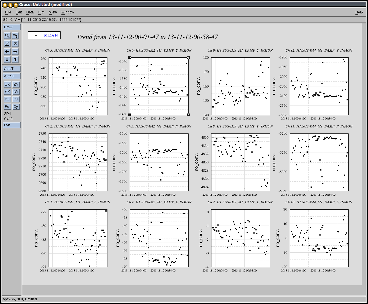
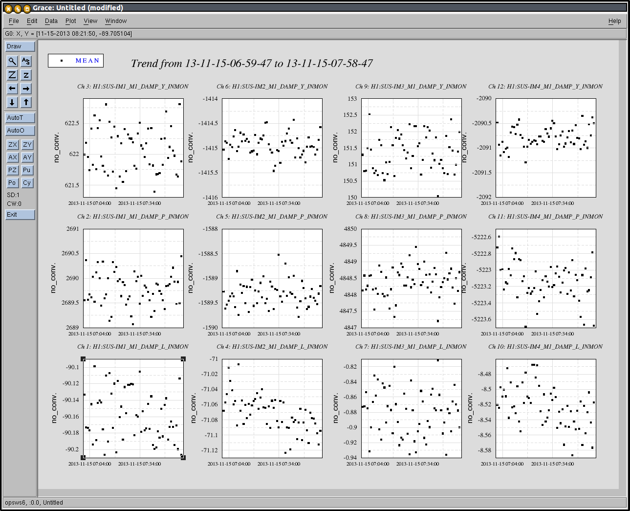
Attached are 10 min trends of the IMs osem signals in the euler basis (Long/Pitch/Yaw) during alignment on monday, and today after restoring the snapfile.
picture 1 : Monday 11/11 from 19:50 to 20:00 PT
picture 2 : Today 11/14 from 10:20 to 10:30 PT
No major shift is seen when comparing both trends
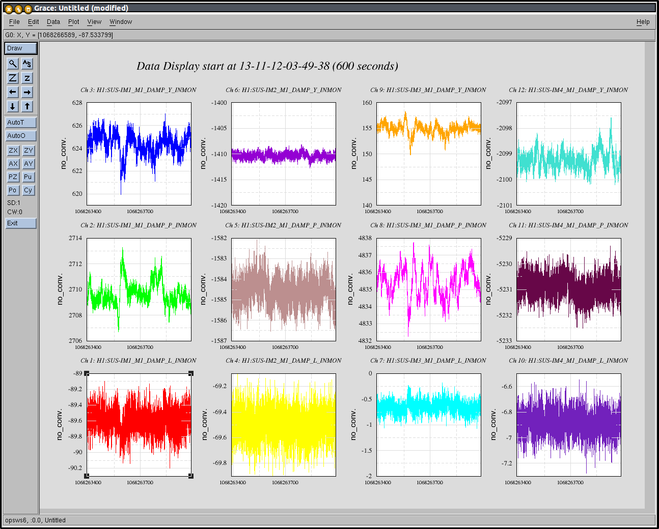
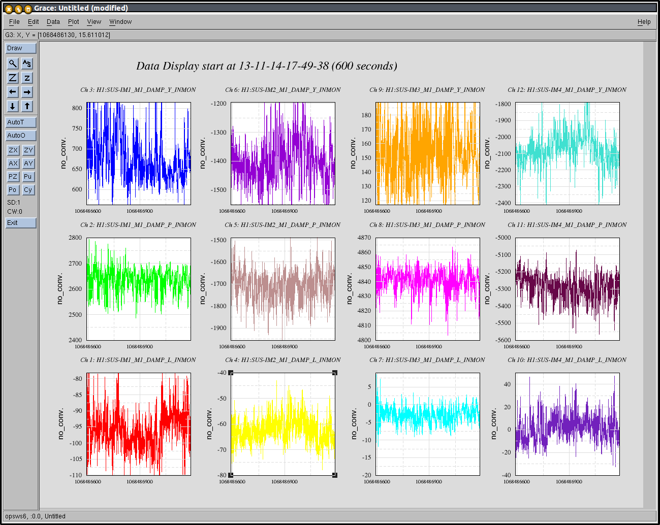
I've looked at the plots, and there is a huge shift of IM1, and shifts that are large on IM2 and IM4. The fact that I changed IM3 on Monday but it's not showing a change is troublesome.
IM1
Delta 800 pitch
Delta 50 yaw
IM2
Delta 115 pitch
Delta 10 yaw
IM3
Delta 0 pitch
Delta 0 yaw
IM4
Delta 70 pitch
Delta 0 yaw
The good alignment time is 5:09PST 11/11, or 1:09UTC 11/12.
To really be confident about your alignment now vs the alignment on Monday, you'll need to trend the alignment slider values, the alignment drive values, and the OSEM readings for 1:05-1:10UTC 11/12, and use that to compare the current IM positions.
[Cheryl Arnaud]
After talking with Cheryl, I attached, a more accurate comparison between two dates : monday 11/11 from 5pm to 6pm during good alignment and thursday during the night (11/15) from midnight to 1am (quieter environment) after the ISS work of thursday, with the restored alignment from monday.
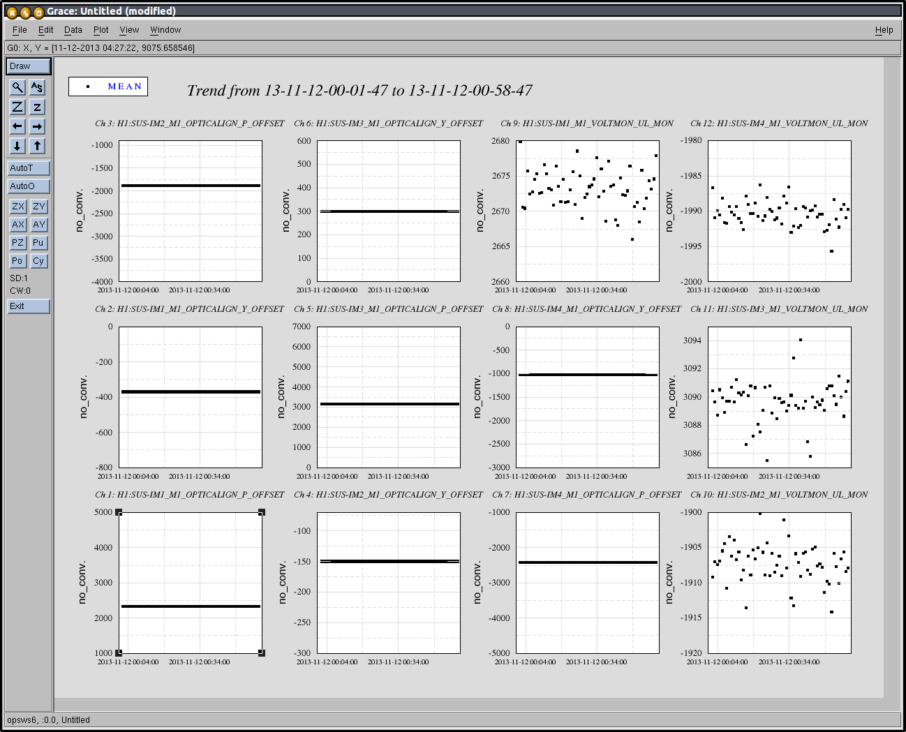
screenshot 1 : position signals in um/urad in the euler basis monday
screenshot 2 : position signals in um/urad in the euler basis thursday night
screenshot 3 : alignment sliders values monday + volt monitor of 1 osem to prove signal is going through the actuation chain
screenshot 4 : alignment sliders values thursday night + volt monitor of 1 osem to prove signal is going through the actuation chain
We should worry if we were seeing a shif of the order of a mrad, which is far from being the case here.
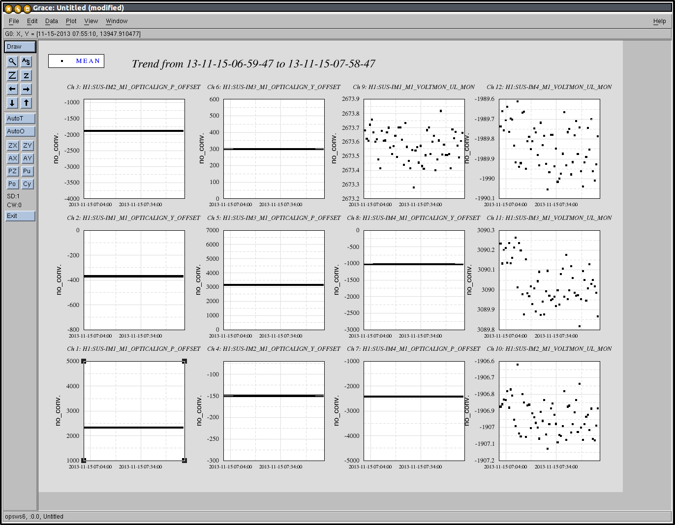
IM1
delta of 80 (not 800) in pitch
