[Kiwamu, Stefan, Joe, Paul]
Last Thursday, measurements of several IMC FSR resonances were taken using the sideband sweep method [see e.g. LLO alog entry 4849].
In short, this method involves phase modulating the light into the IMC with a swept sine signal from a network analyzer and observing the signal in transmission of the IMC with an RF photodiode to observe various optical resonances within the cavity.
In this case, the RF photodiode was the broadband REFL AIR photodiode on ISCT1. The network analyzer output was split with a power splitter, with one output going to the REF input, and the other fed to a mini-circuits RF amp with a gain of 18.8dB. The network analyzer source Voltage was tuned to give around 10Vpkpk output from the RF amplifier. The RF amplifier output was then passed to the 45.5MHz input of the EOM on the PSL table. The RF output of the REFL AIR photodiode was connected to the A input of the network analyzer.
When the sideband frequency gets close a multiple of the FSR, a broad peak in the the N.A -->REFL AIR PD transfer function is observed, as reported in [1] and subsequent errata [2]. According to these references as well as Araya et al. [3] this broad peak is only present if there is an offset in the length/frequency lock of the cavity (more on that in a forthcoming post). There is a narrow dip in this peak however, when the sideband frequency approaches the exact FSR multiple frequency. The frequency at which this dip hits a minimum is an integer multiple of the cavity FSR.
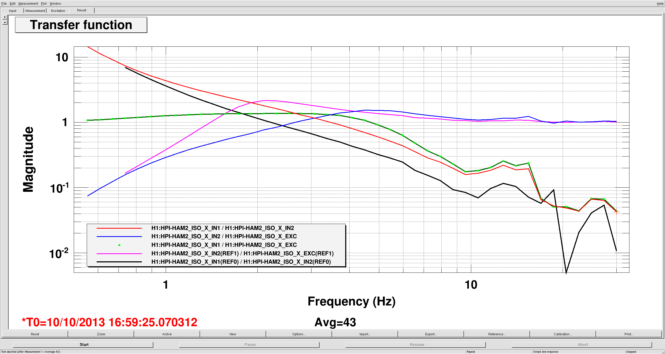
The first attached plot shows 5 FSR peaks measured in this way. Since we apply the signal to the 45.5MHz input of the EOM, the modulation depth, and thus the SNR of the measurement, is low at frequencies far from 45.5MHz (e.g. the 18.2MHz FSR, the 27.3MHz FSR and the 54.5MHz FSR). The 36.4MHz peak and the 45.5MHz peak measurements came out the best, so I fitted the central dip using a simple Lorentzian function to estimate the frequency of the minima (see second attached plot).
The results from these two fits are summarised and compared to the design values in the following table:
|
Parameter |
36.6MHz peak fit value (nFSR=4) |
45.5MHz peak fit value (nFSR=5) |
Design value |
|
Frequency |
36397349 Hz |
45496442 Hz |
N/A |
|
f/n = FSR |
9099337 Hz |
9099288 Hz |
9099471 Hz |
|
L |
16473.31 mm |
16473.40 mm |
16473 mm |
The calculated lengths from each peak fit agree to within 100um, and are within 0.5mm of the design length.
If higher precision on this measurement is required later on, we could try syncing the network analyzer with a rubidium standard, and also try implementing the measurement technique described in [3]. Also, separately using the 9.1MHz input of the EOM to measure a greater sample of FSRs could be helpful.
[1] K. Skeldon and K. Strain, Applied Optics Vol 36, Number 27 (1997): http://www.opticsinfobase.org/ao/abstract.cfm?uri=ao-36-27-6802
[2] K. Skeldon and K. Strain, Applied Optics Vol 37, Number 21 (1998): http://www.opticsinfobase.org/ao/abstract.cfm?uri=ao-37-21-4936
[3] A. Araya et al, Applied Optics Vol 38, Number 13 (1999): http://www.opticsinfobase.org/ao/abstract.cfm?uri=ao-38-13-2848