Summary: The HIFO-Y feature at 70 Hz is produced by both ALS periscopes on ISCT1. The features below 1 Hz are coherent with ground motion and OSEM sensors. We did not identify the dominant source of noise between 0.8 and 2 Hz, though this band contributes little to the HIFO-Y RMS. We may be able to reduce the RMS by using cylindrical periscopes that have resonant frequencies closer to 250 Hz, but we will also likely get a free factor of about two reduction in RMS (in the 60-80 Hz band) after noisy installation activities cease.
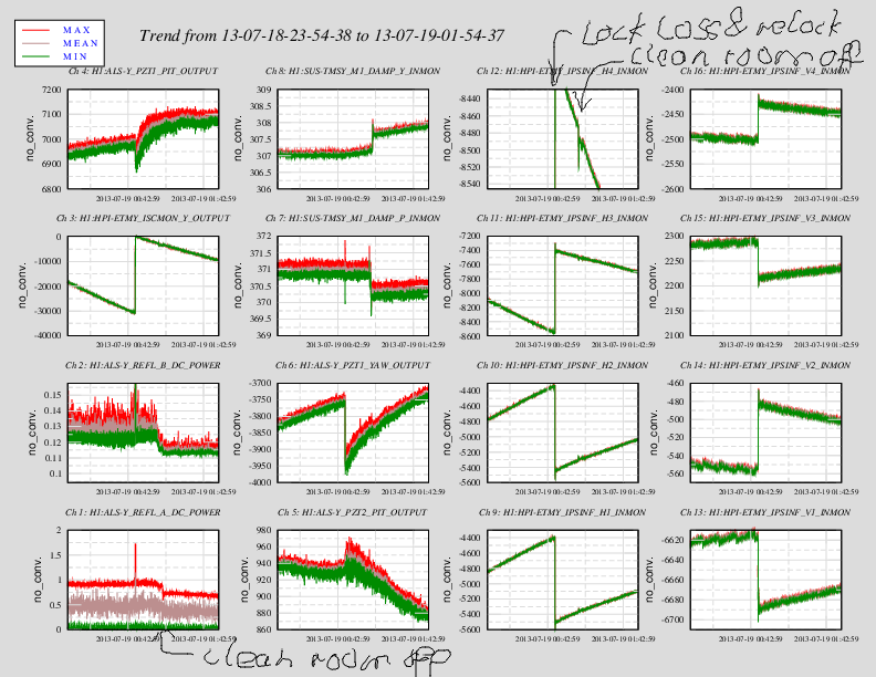
Vibration coupling to HIFO-Y was reduced by establishing a science mode and a commissioning mode for PSL air handling (Link). There remain two frequency bands that contribute significantly to the HIFO-Y RMS, 60-80 Hz, and 0.3-0.7 Hz.
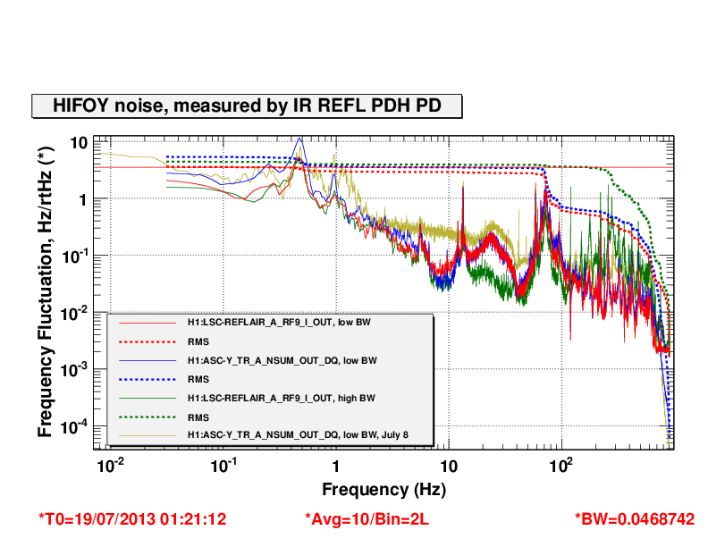
Figure 1 shows spectra for the PEM sensors that we recently installed whose signals have the highest coherence with the HIFO-Y signal above 1 Hz. The PSL was operating in science mode. The accelerometer that we mounted temporarily on one of the two similar ALS telescopes on ISCT1 (red trace), the one that carries infrared light, has high coherence with and similar shape to the 50-100 Hz band noise in HIFO-Y (red and black traces). Further excitation tests on the ISCT1 table confirmed that the 70 Hz feature is associated with the lowest resonant frequencies of both ALS periscopes. Neither the green nor the infrared periscope appears to dominate, and I could find no particular source of, e.g., backscattering noise. It may be that the noise is associated with the differential motion of the two periscopes in the locked path.
The other coherence features in the spectrum are, at about 180 Hz, one of the higher-Q resonances of the PSL periscope – perhaps driven by vibrations at the 60 Hz harmonic. These 180 Hz vibrations may be smaller after installation, and if they are not suffieciently smaller, we may be able to damp at this frequency. The 12 and 13 Hz coherence regions are produced by table sway resonances of ISCT1. I am less certain about the feature between 5 and 6 Hz, but there is a building resonance at that frequency excited by wind. The seismometers, some distance from the PSL and ISCT1, also show strong coherence with HIFO-Y at 5.5 Hz, supporting the building resonance interpretation.
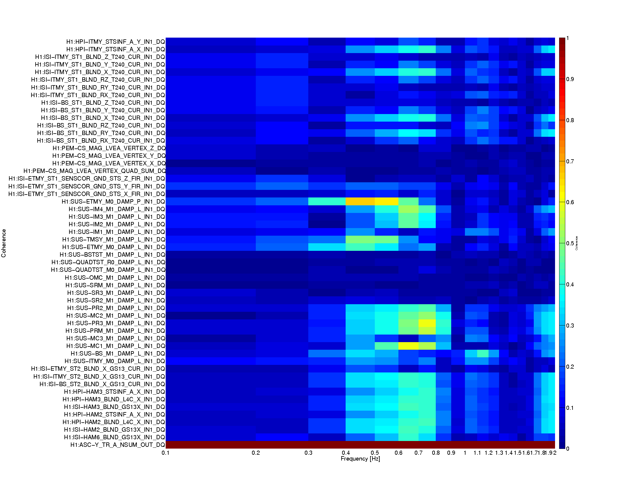
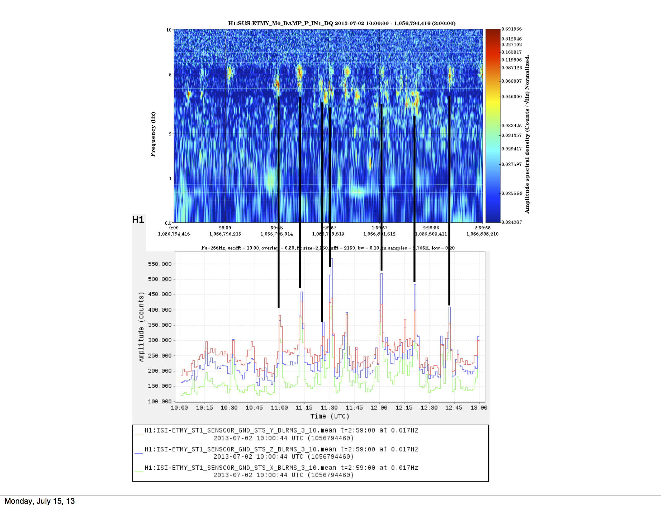
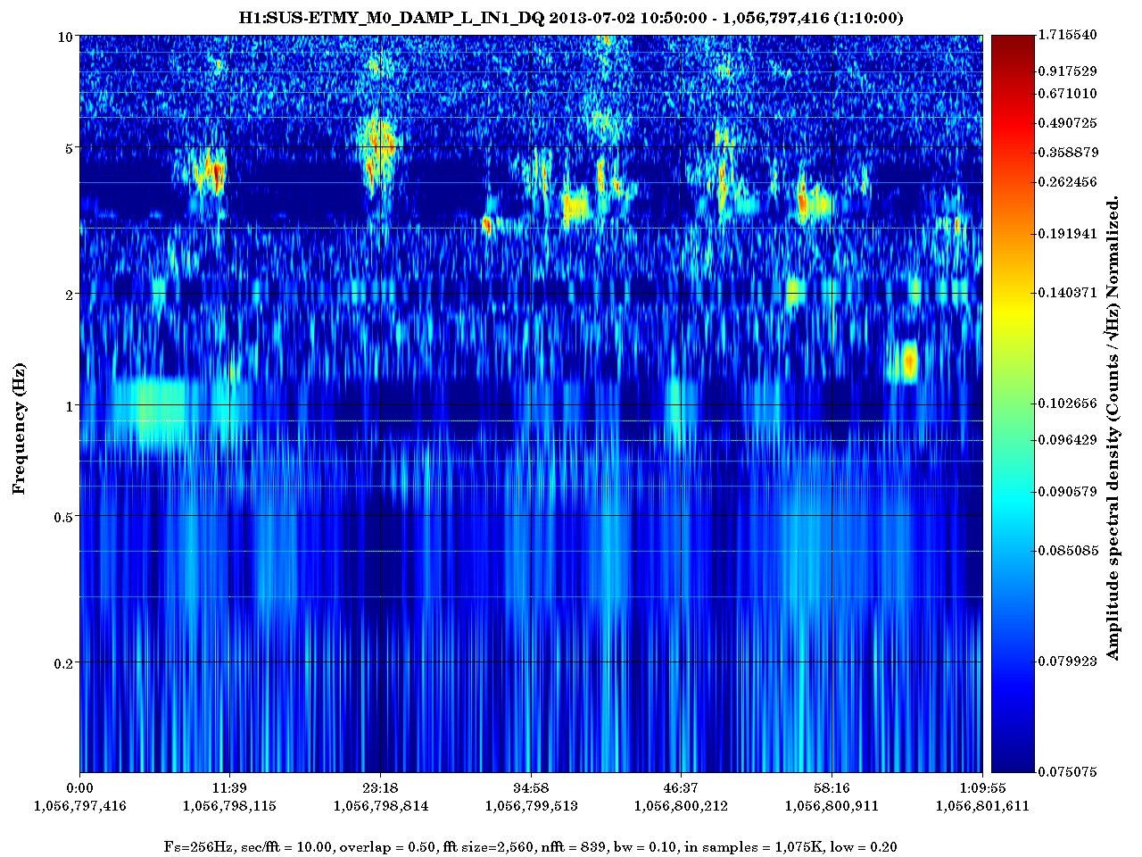
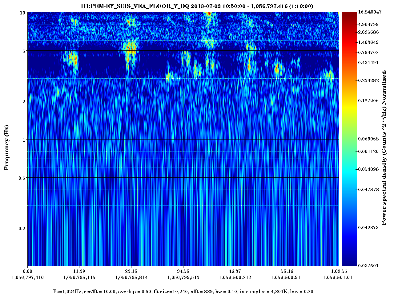
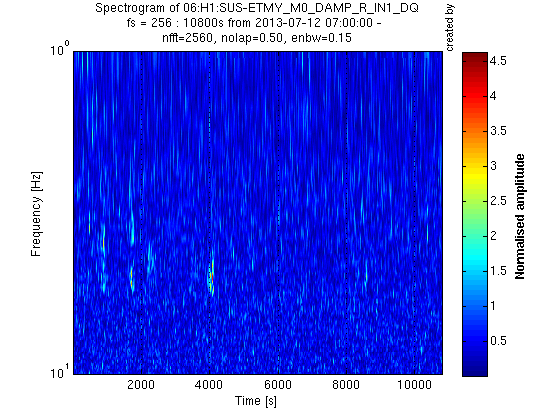
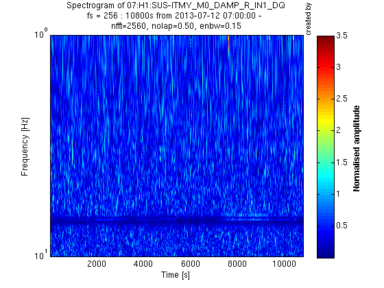
Coherences with features in the low frequency region are shown in Figure 2. Seismometer and OSEM signals have high coherence with the HIFO-Y signal, except in the band between 0.8 and 2 Hz. We did not find the source of noise in this region.
It may be useful for the DetChar group to look for coherence in this 0.8-2 Hz band (I only guessed the most important channels) and, if none is found, search for upconversion between the 0.1-0.7 Hz band and, say, the 1.2-1.8 Hz band.
It may be possible to reduce the ALS RMS by replacing the periscopes with periscopes that have higher resonant frequencies. We can probably get from 70 Hz to about 250 Hz by using the cylindrical periscopes from iLIGO. Stefan also suggested that we use a single periscope for both the red and green beams, reducing differential motion. I placed an accelerometer on the double periscope, also on ISCT1, and found the lowest resonance to be about 60 Hz. It is not clear to me whether putting both beams on a 60 Hz periscope or keeping them separate on 250 Hz periscopes, would result in the better RMS.
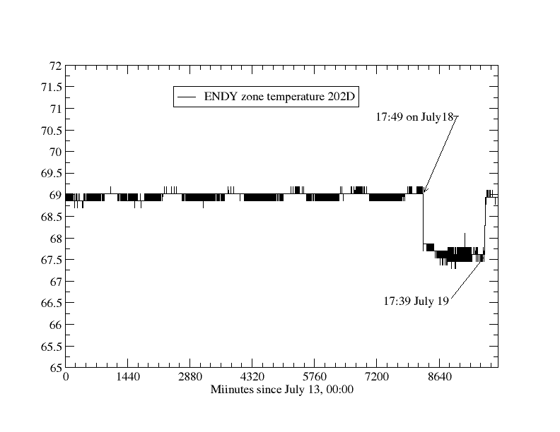
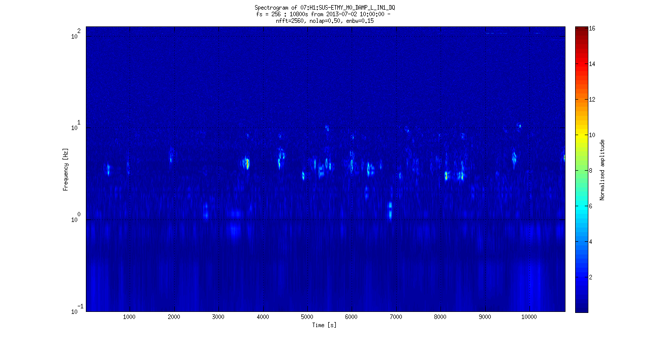
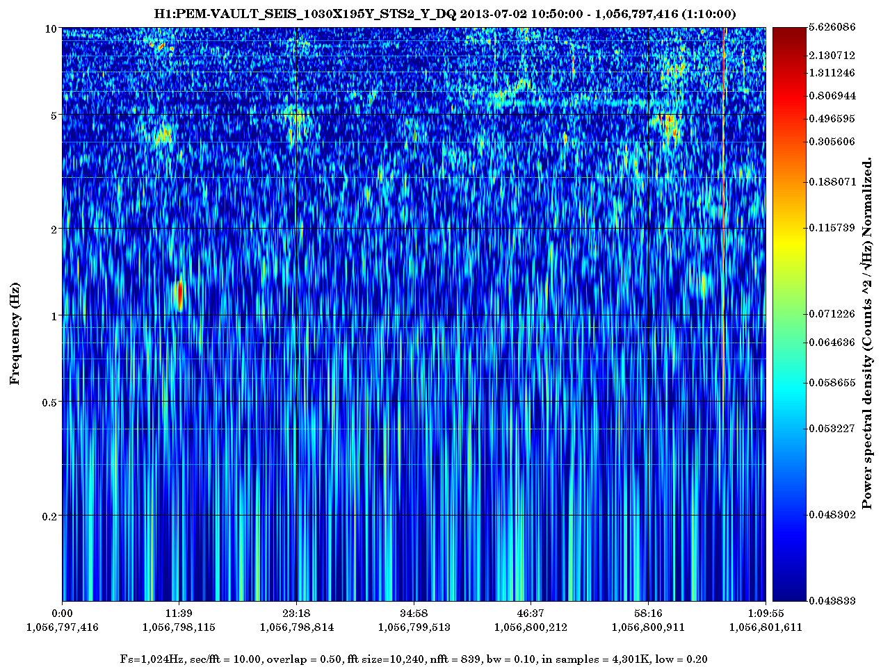
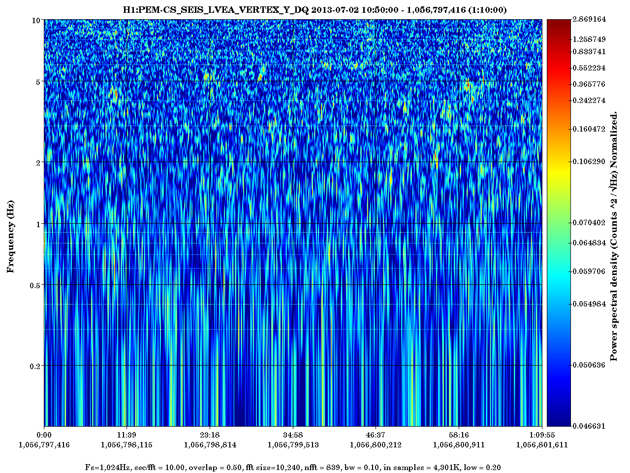
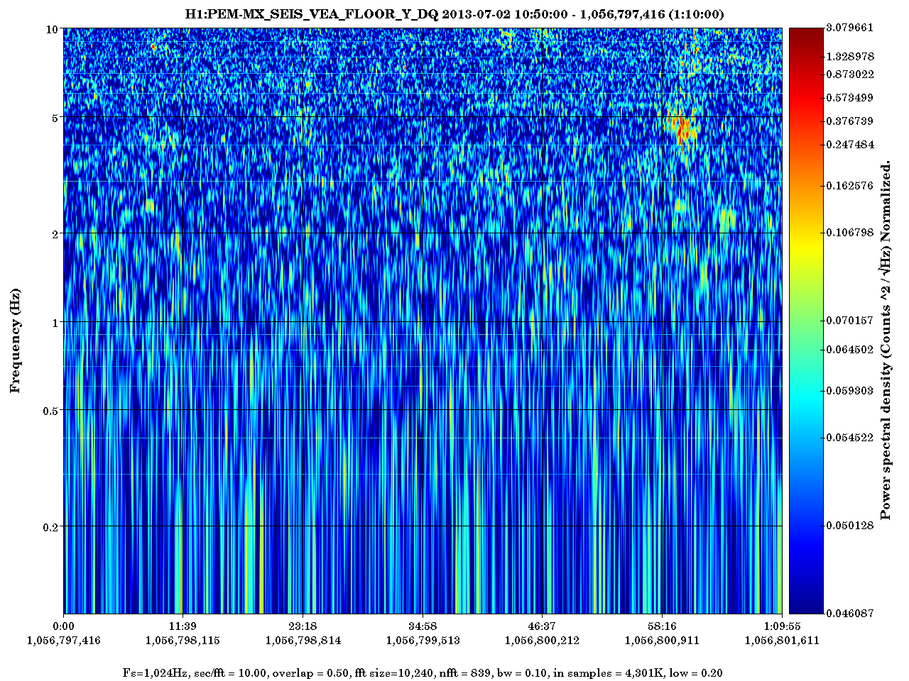
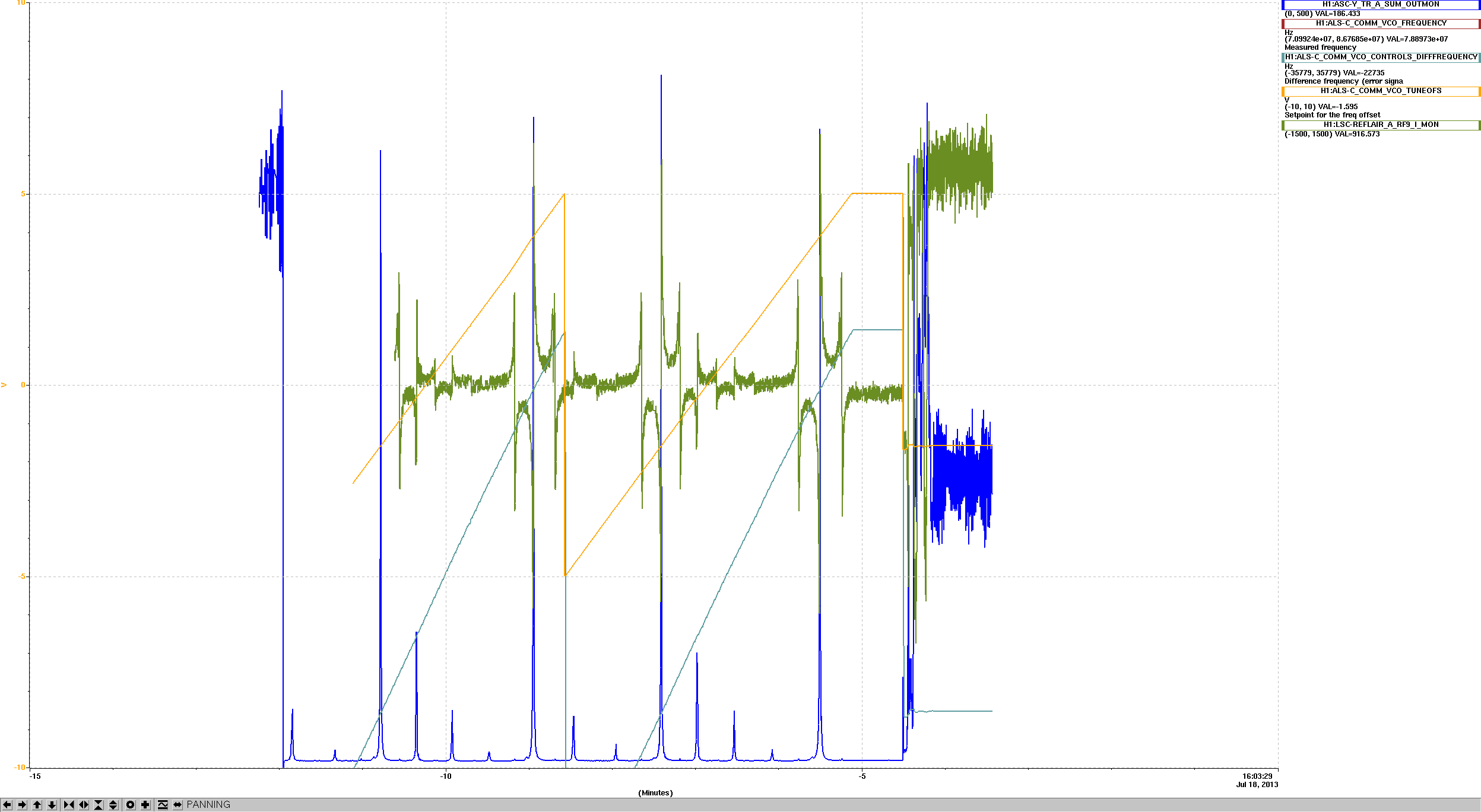
We may get a free factor of about 2 reduction in RMS contribution from the periscope motion after installation activities cease, because Figure 3 shows that ground motion in this band was about a factor of 2 lower during S6. After installation we would expect the ground motion to drop back down to the S6 level, reducing the need to change periscopes.
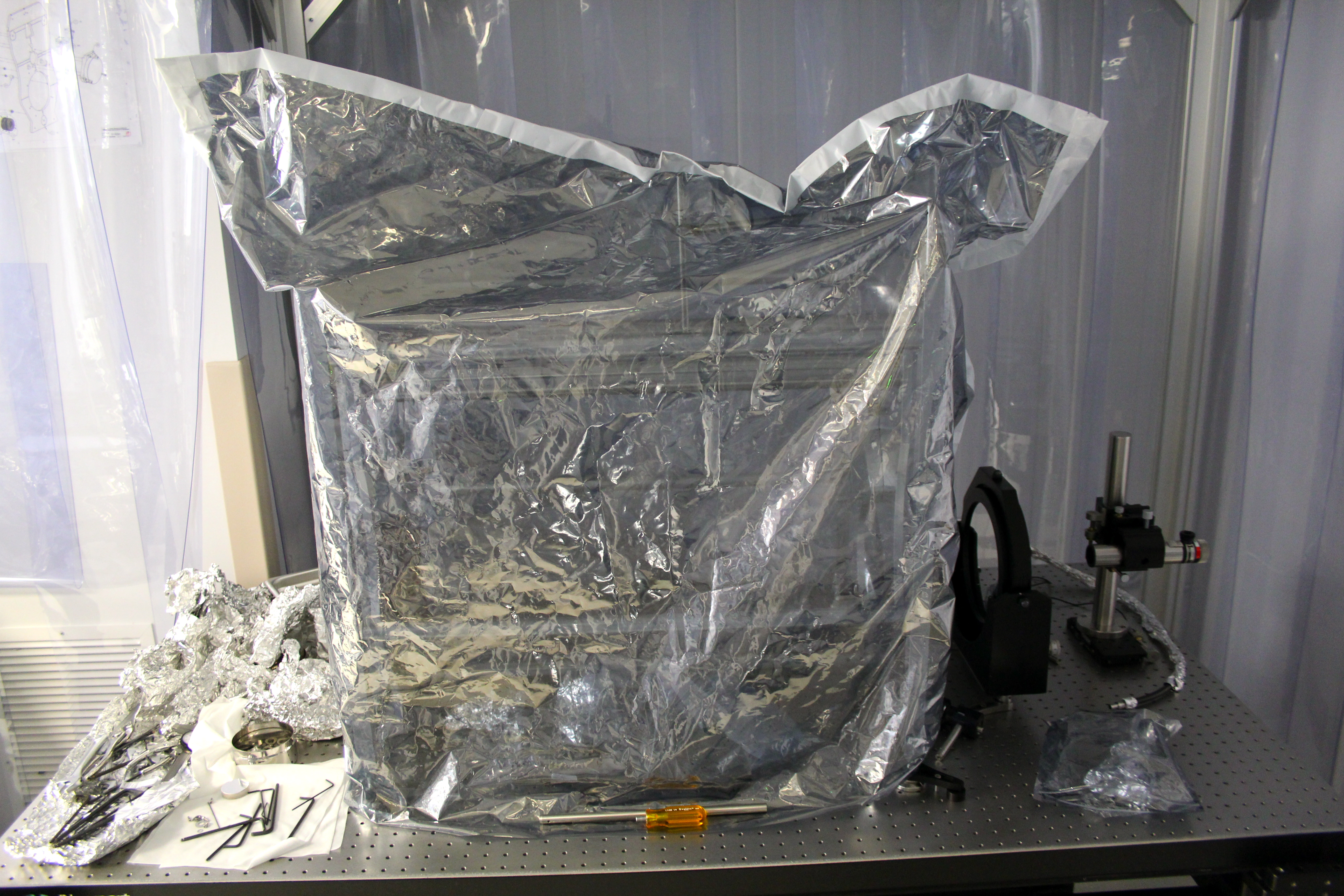
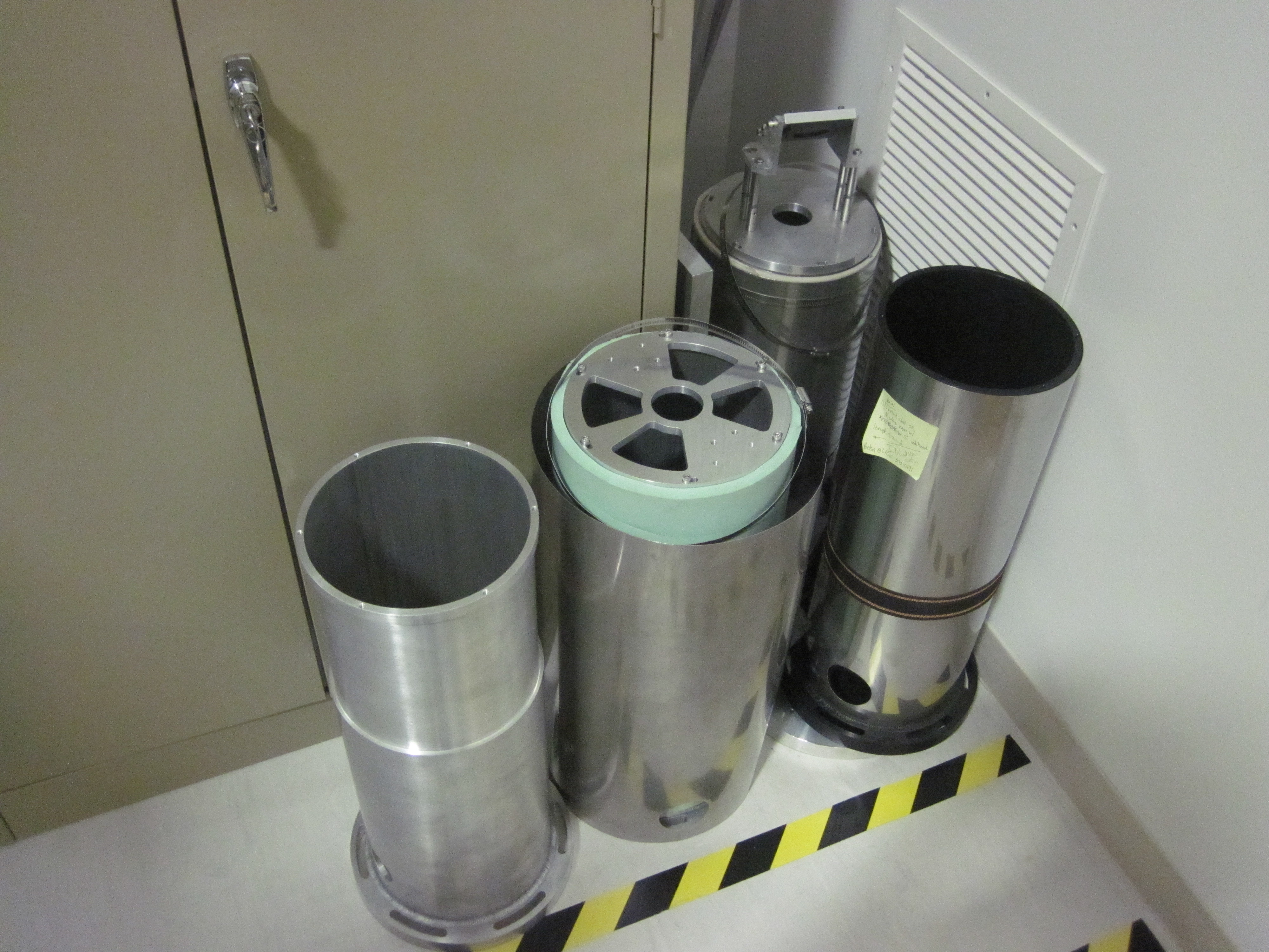
Figure 4 is a photo of the cylindrical periscopes from iLIGO that we gathered together near the squeezer bay with Corey’s help. None of them are complete, some parts would probably have to be remade.
Robert Schofield, Stefan Ballmer, Emily Maaske, Terra Hardwick, Vincent Roma, Brian Dawes, Tristan Shoemaker

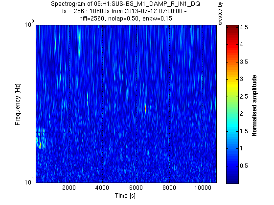
I have computed the coherence between H1_ASC-Y_TR_A_NSUM_OUT_DQ and many seismic and suspension channels in the 0.1-2 Hz band. As Robert noted, there is significant coherence between many of the seismic channels and the output channel. There are also a few suspension channels that also indicate high coherence in the 0.6-0.8 Hz band. I can also broaden my scope if there is interest. This is a slightly random channel list, and if there are channels that people would think could be interesting, I am happy to include them.