controls@h1build release 0$ make install-h1isiham3
command is make install-h1isiham3
Installing system=h1isiham3 site=lho ifo=H1,h1
Installing /opt/rtcds/lho/h1/chans/H1ISIHAM3.txt
Installing /opt/rtcds/lho/h1/target/h1isiham3/h1isiham3epics
Installing /opt/rtcds/lho/h1/target/h1isiham3
Installing start and stop scripts
/opt/rtcds/lho/h1/scripts/killh1isiham3
Performing install-daq
Updating testpoint.par config file
/opt/rtcds/lho/h1/target/gds/param/testpoint.par
/opt/rtcds/rtscore/advLigoRTS-2.6.2/src/epics/util/updateTestpointPar.pl -par_file=/opt/rtcds/lho/h1/target/gds/param/archive/testpoint_130607_162226.par -gds_node=57 -site_letter=H -system=h1isiham3 -host=h1seih23
Installing GDS node 57 configuration file
/opt/rtcds/lho/h1/target/gds/param/tpchn_h1isiham3.par
Installing auto-generated DAQ configuration file
/opt/rtcds/lho/h1/chans/daq/H1ISIHAM3.ini
Installing EDCU ini file
/opt/rtcds/lho/h1/chans/daq/H1EDCU_ISIHAM3.ini
Installing Epics MEDM screens
Running post-build script
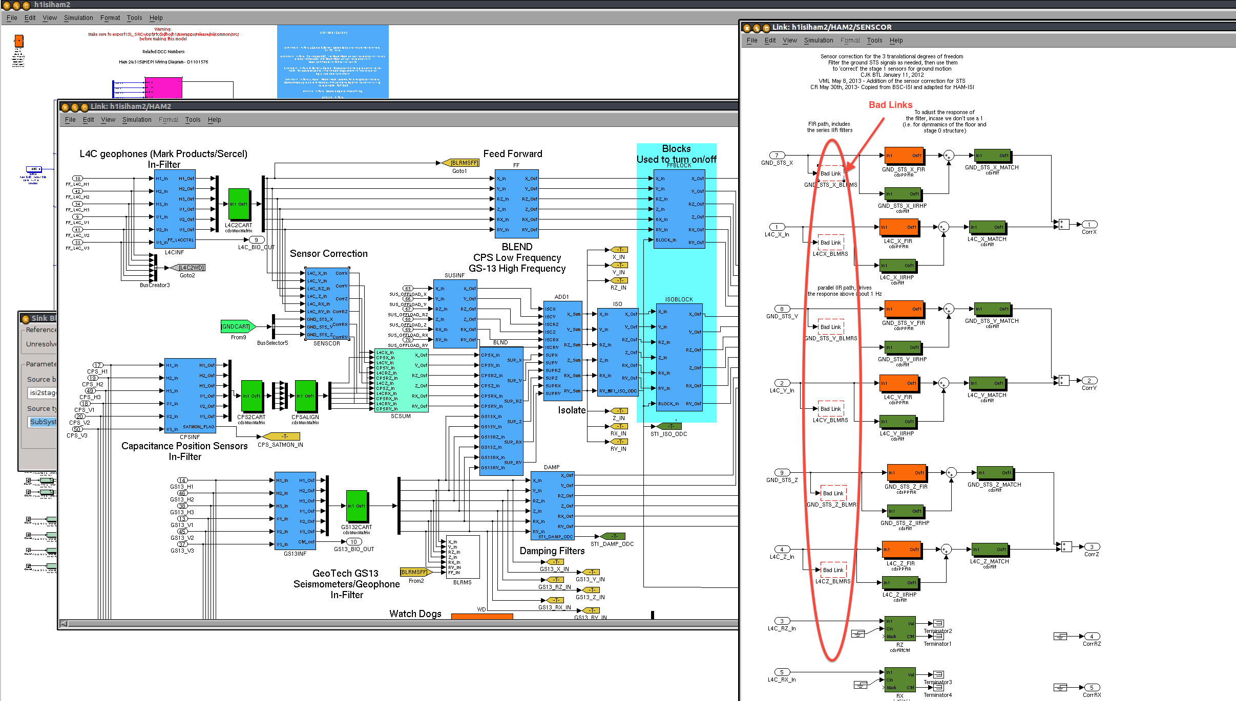
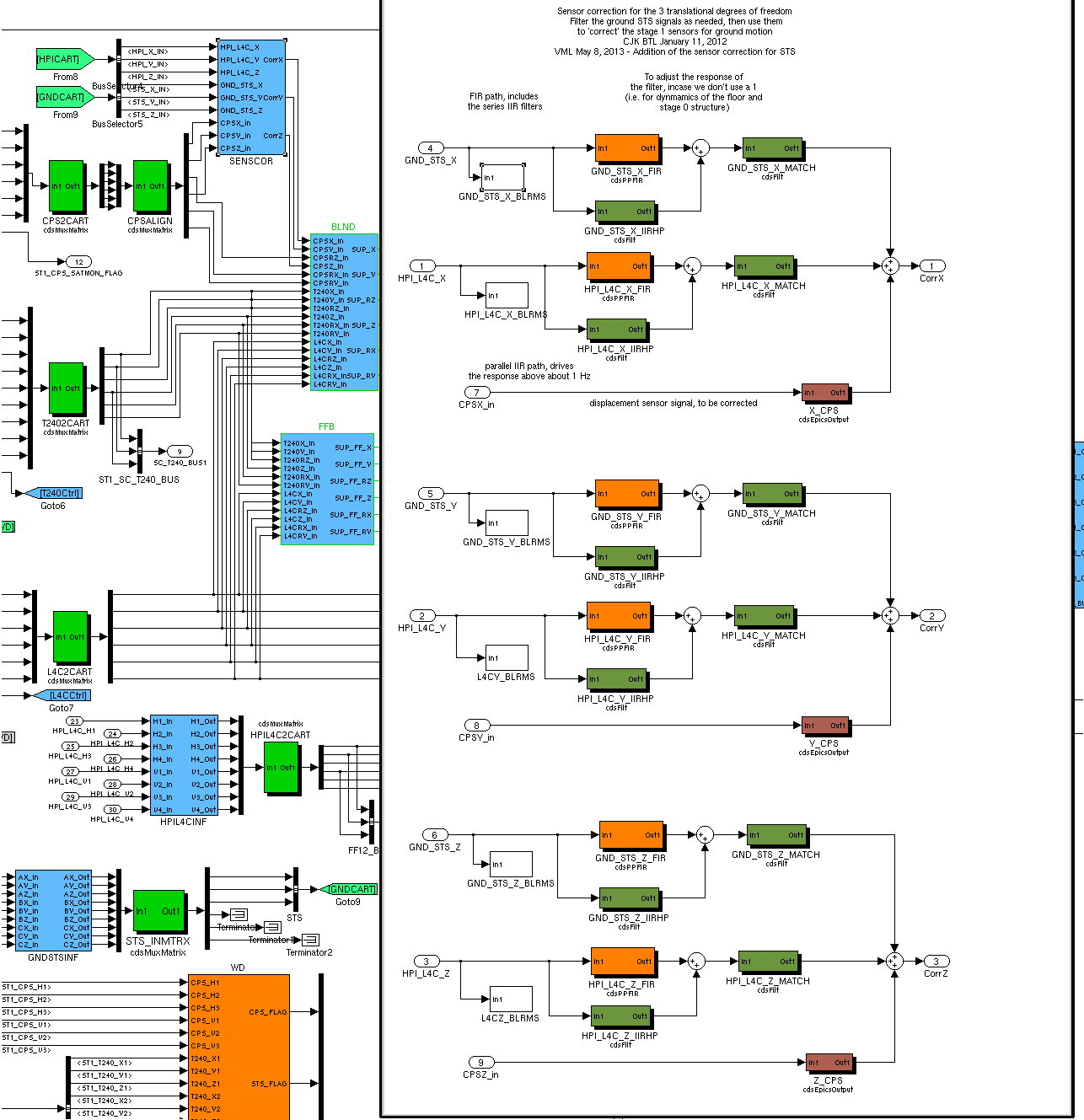
ERROR: For part: "isi2stagemaster/ISI2STAGE/ST1/SENSCOR/X_BLRMS"
Could not find the proper library reference.
Your model may be referencing a different source model than what is in the current library path.

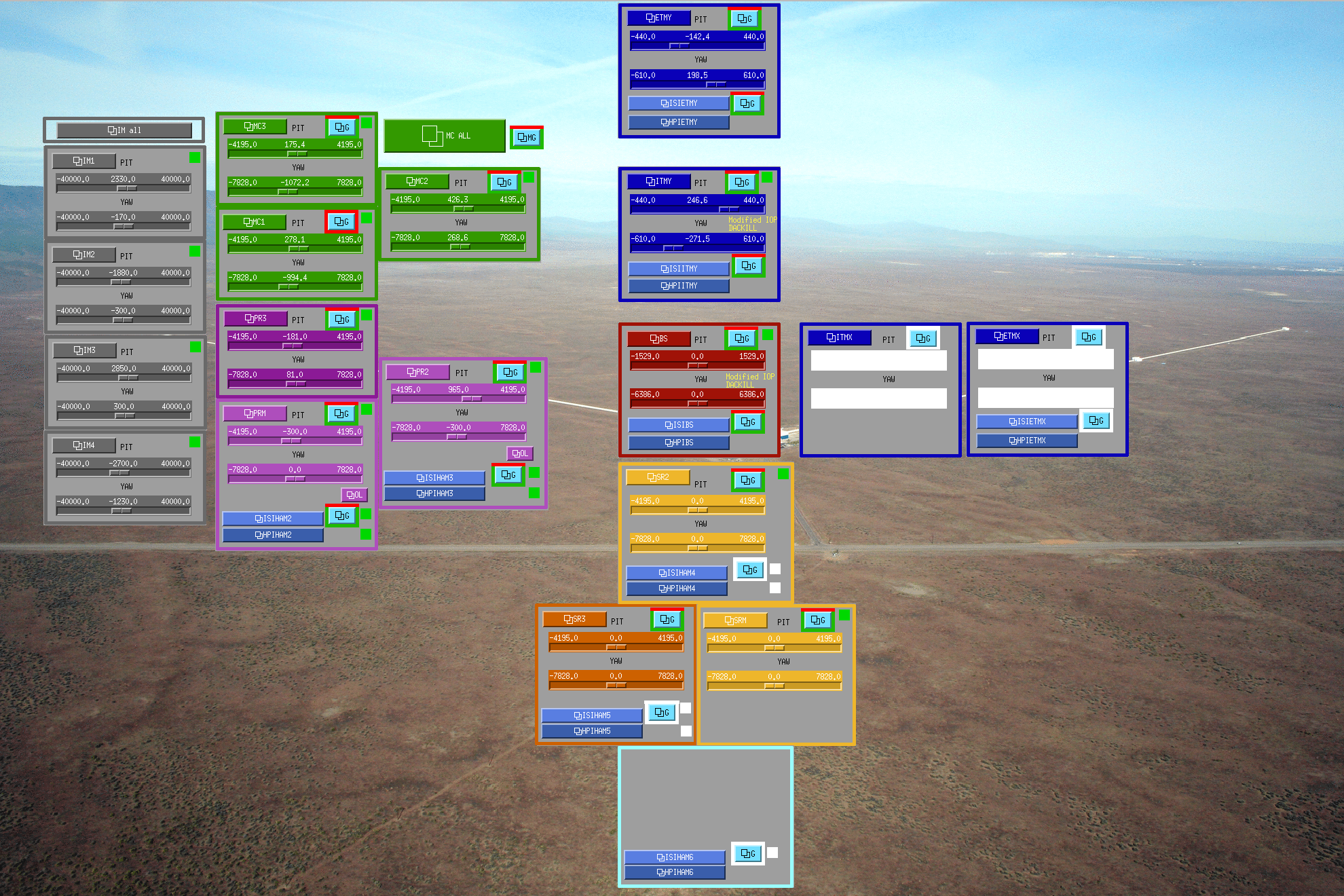


I was measuring consecutively MC1/MC2/MC3 M2 to M2 and M3 to M3 transfer functions over the week end. The script can be killed by closing matlab windows on workstation 2, and overwriting the current excitation with awggui.
I will make sure to post an aLog next time.