stefan.ballmer@LIGO.ORG - posted 00:10, Wednesday 19 June 2013 - last comment - 12:20, Wednesday 19 June 2013(6801)
ALS common mode feed-back, including 4Hz:4kHz boost closed - IR beam stays on top of resonance
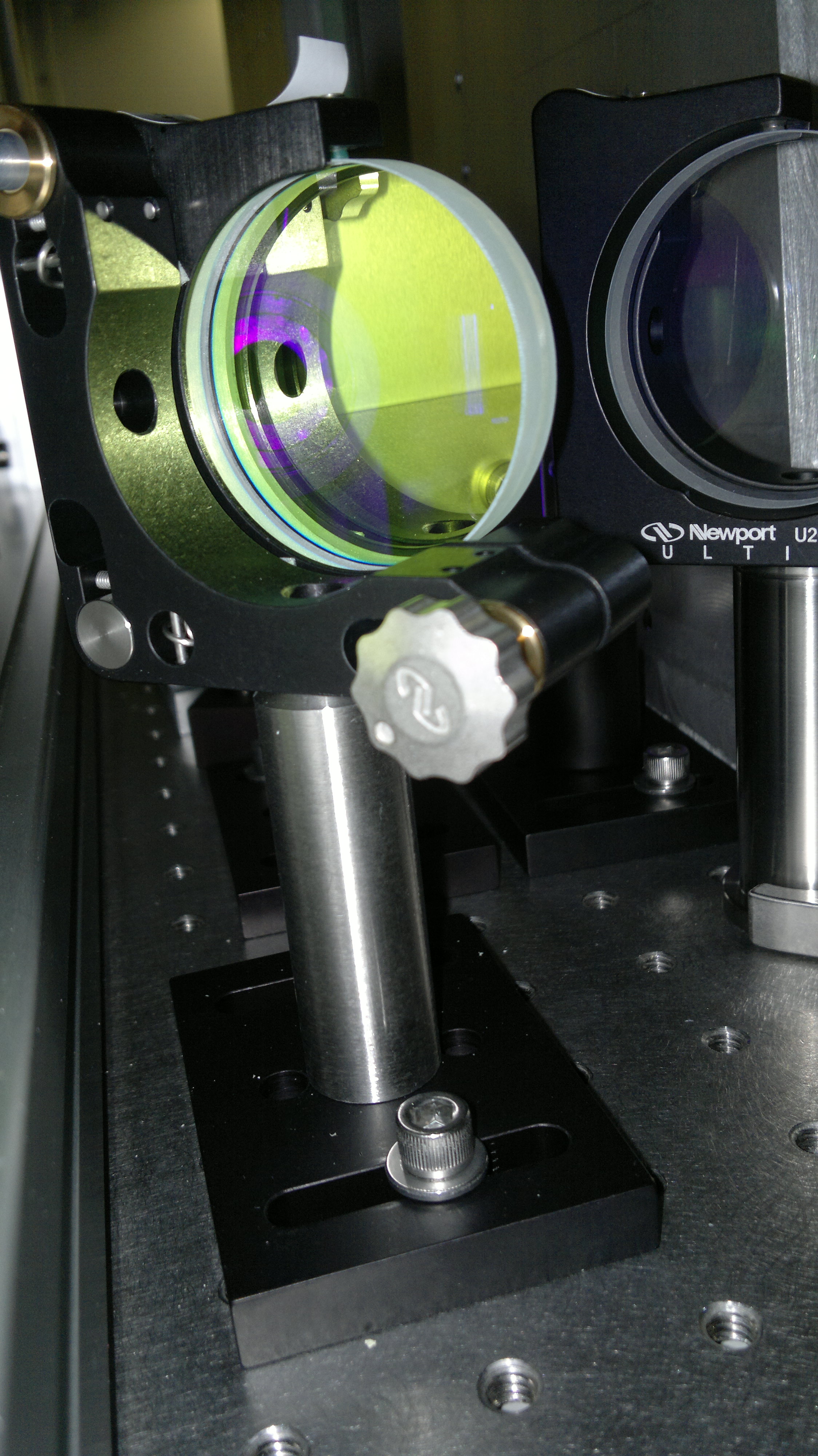
(Alexa, Chris, Kiwamu, Lisa, Matt, Stefan)

We successfully handed of the ALS common mode feedback to MCL, including AO path, and engaged the common boost. This kept the IR arm power within about 20% from its max.

The setup for our PLL was as follows:
- SR560 A: gain -2; pole at 300kHz, hooked up to Imonn, feeding back to VCO tuning
- SR560 B: gain: 5; pole 100Hz, hooked up to output of SR560 A, output goes to a gain of 2 analog box, and then to the CM board input 1.

Tricks we used along the way:
 -The MC notch filters were all turned off.
- First was AC-couple the MC_L path and turn on the REFL_SLOW path at low gain. This brings the PLL into its lock range by moving the IMC.
- Next we turn off the MCL path
- Then we increase the ALS_MCL path by a factor of 30, bringing its x-over to about 150Hz. THen we engage a digital LF boost.
- Next the AO path is turned on until the x-over drops to about 100Hz.
- With the H1:LSC-REFL_SERVO_IN1GAIN at +15dB we engage the analog CM boost filter.


Some gains we used in the final state:
H1:LSC-REFL_SERVO_IN1GAIN 15
H1:LSC-REFL_SERVO_FASTGAIN 0
H1:IMC-REFL_SERVO_IN1GAIN 0
H1:IMC-REFL_SERVO_IN2GAIN 2
H1:IMC-REFL_SERVO_FASTGAIN 0

The scripts that do all the magic, CARM_down and CARM_handoff are in
/opt/rtcds/userapps/release/als/h1/scripts

more pictures to come...

This is a video of the beatnote in an RF analyzer being stablised by the CARM servo and brought to 79.235 MHz by feeding the signal back to the MCL and the AO path.
[Chris, Kiwamu]
It seems the unlock events were related to the VCO feedback applied from the end PDH locking. Every time the signal H1:ALS-Y_ARM_OUT exceeded approximately -15000 counts we lost the lock of every loops. A reason is that we didn't use the longitudinal offloading to ETMY which helps us this VCO range issue as we thought this offloading could excite the pitch motion of ETMY. If this hypothesis is true we should be able to elongate the lock stretch by enabling this offload path with a time scale of 5 min. which was observed in the trend.
The attached is the trend of most of the relevant signals.