cheryl.vorvick@LIGO.ORG - posted 05:45, Tuesday 07 May 2013 (6269)
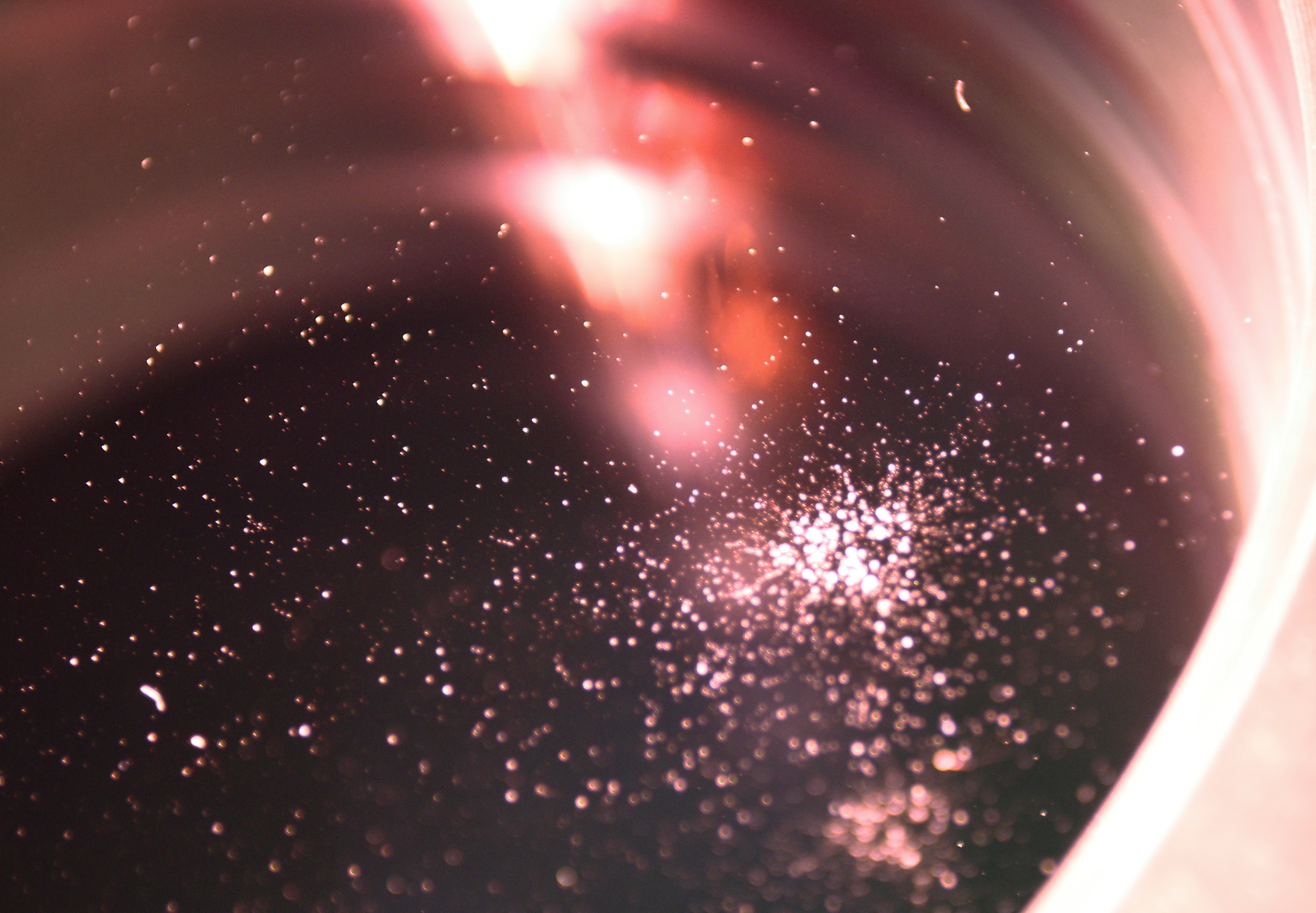
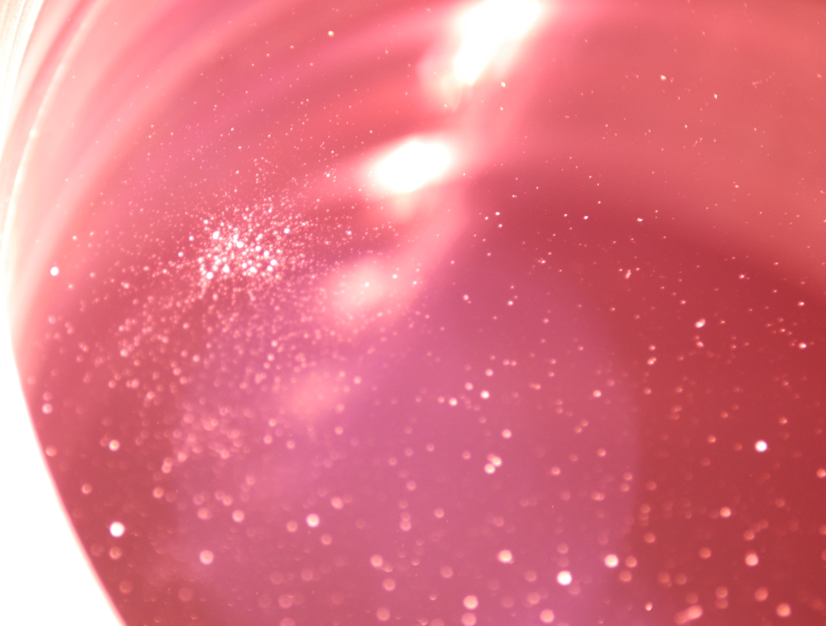
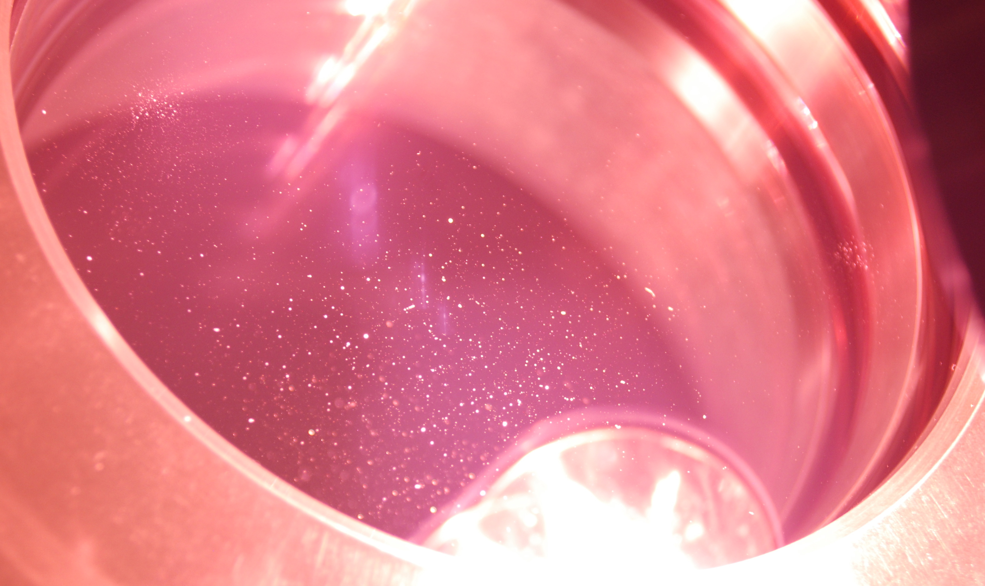
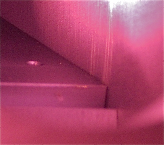
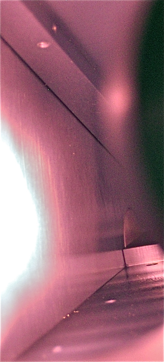
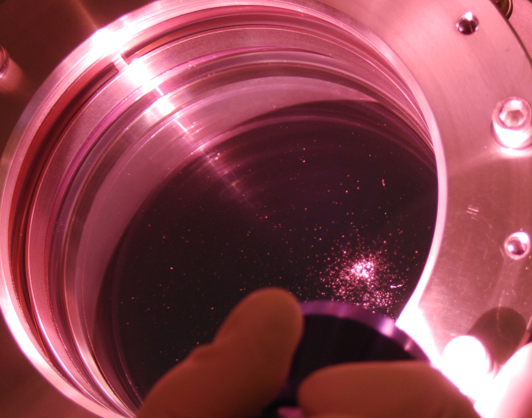
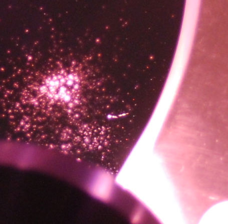
PSL viewport is covered with particulate.
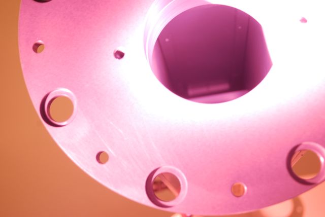
- Joe D., Cheryl

Joe and I uncovered the PSL viewport - the double viewport on HAM1.  The shutter assembly was disconected from the viewport and slid back to give us a full view of the viewport surface, and it is covered with particulate.  The source of the particulate on the viewport is the shutter assembly and cover plate.

There are two areas with a very high concentration of particulate, and it was quickly apparent that they line up exactly with two through holes that attach the shutter box to the viewport cover  plate.  The particulate in these two areas are uniform size and finer grained than the other particulate.

There is particulate that is concentrated at the exit of the tube from the PSL that is various sizes and is concentrated on the middle to bottom third of the viewport.

There are also some large particles scattered across the viewport.  One looks like a fiber, and the others could be fibers, hair, or thin metal shavings.

I looked into the shutter assembly and saw that the shutter itself has worn away the anodization on both sides of the shutter box, and there is particulate on the shutter's surface.

One cluster of particulate on the shutter lines up with a through hole on the top of the shutter box.  The screw holds the removable plate that allows the input beam, reflected from the viewport, to project onto the PSL enclosure wall.

The shutter assembly needs to be removed from the viewport, modified and cleaned, and then reinstalled.

The viewport needs to be cleaned, but most of the particulate is metal.  FC is our usual choice for viewports, but with this level and type of particulate, scratching the viewport surface is possible.  Other procedures that are possible in the optics lab may also scratch the viewport.
Images attached to this report