Gerardo, Gerardo Jr., Symon, Keita, Sheila, Kiwamu
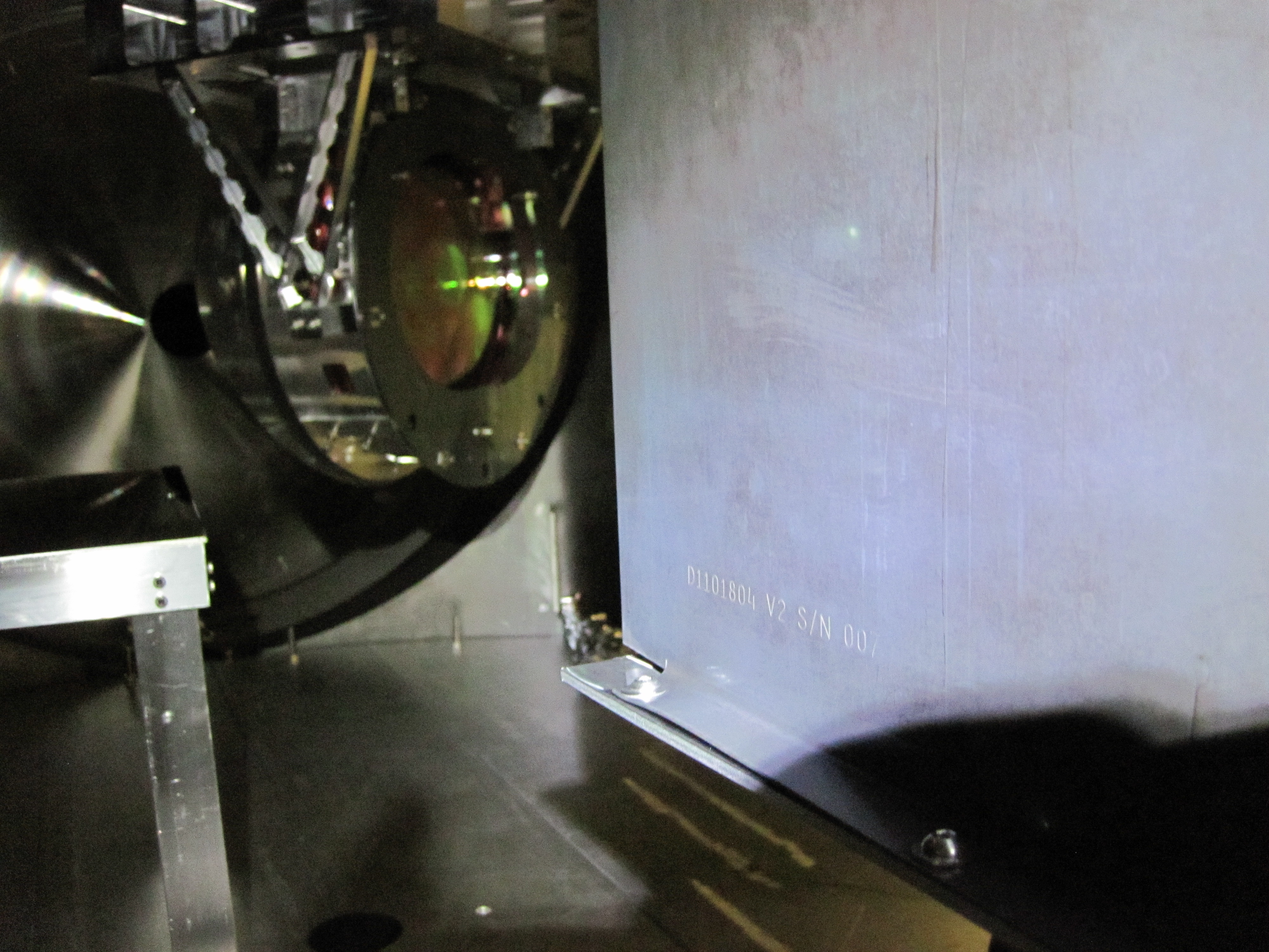
We moved ISCT1 closer to HAM1 at its west side, installed a beam duct and confirmed that the PSL sample beam nicely goes through the viewport to ISCT1.
We are ready to align the optics on ISCT1 for the doubling test to generate the green light.
ISCT1 shift:
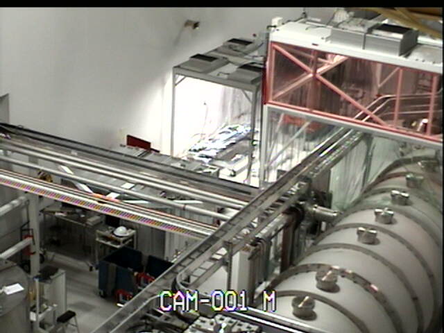
The ISCT1 enclosure which had been put afar from the HAM1 chamber was rolled closer to HAM1. Before moving it the clean room was also rolled toward south to accommodate ISCT1 as the clean room was too close to let ISCT1 go in. At the moment the distance between HAM1 and ISCT1 is that one person can just get through between the HEPIs and the enclosure. Also, as a part of the preparation of the laser barriers we put two black metal panels at the north side of the enclosure. The panels were wiped before they got in the clean room.
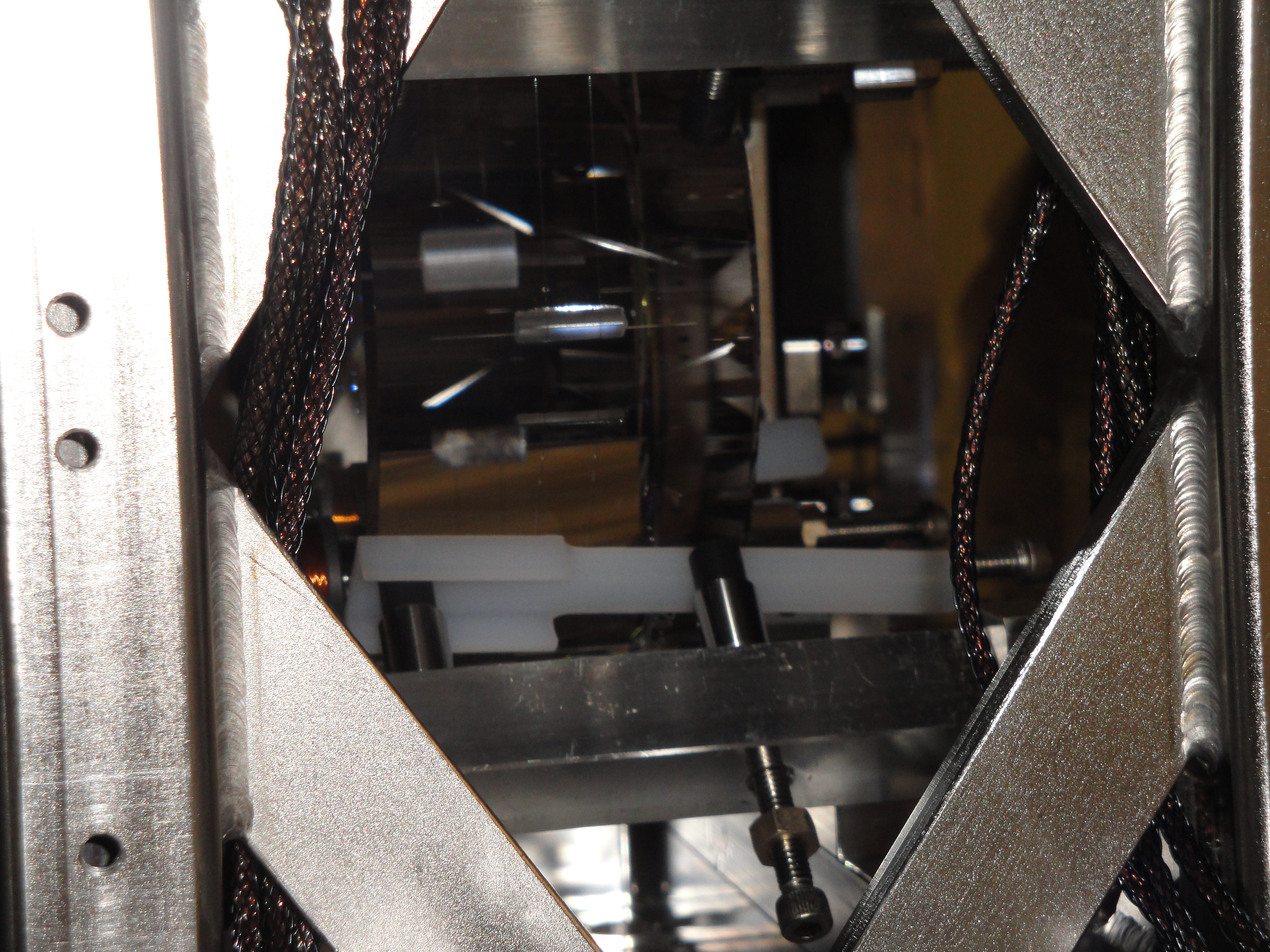
Beam spot position check :
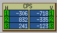
Then we transitioned the LVEA to laser hazard for checking the spot position at the lower right viewport and the enclosure hole. At the HAM1 viewport the beam was at almost the center of the guillotine guard (as we aligned the in-vac mirror the other day) and slightly off in mainly the horizontal direction by 1 cm toward north, which is small enough comparing with the viewport diameter. At the enclosure hole it was off from the center by 4-ish cm toward south and by 4-ish cm higher. This is fine as the hole diameter is 10". We are satisfied with this alignment and hence there is no need to steer the beam with the in-vac steering mirror. At the moment the beam doesn't hit the upper periscope mirror in the ISCT1 enclosure but the beam height looks already perfect. So we just need to translate the periscope by ~ 4 cm to catch the beam, which is within our expectation.
Installation of duct:
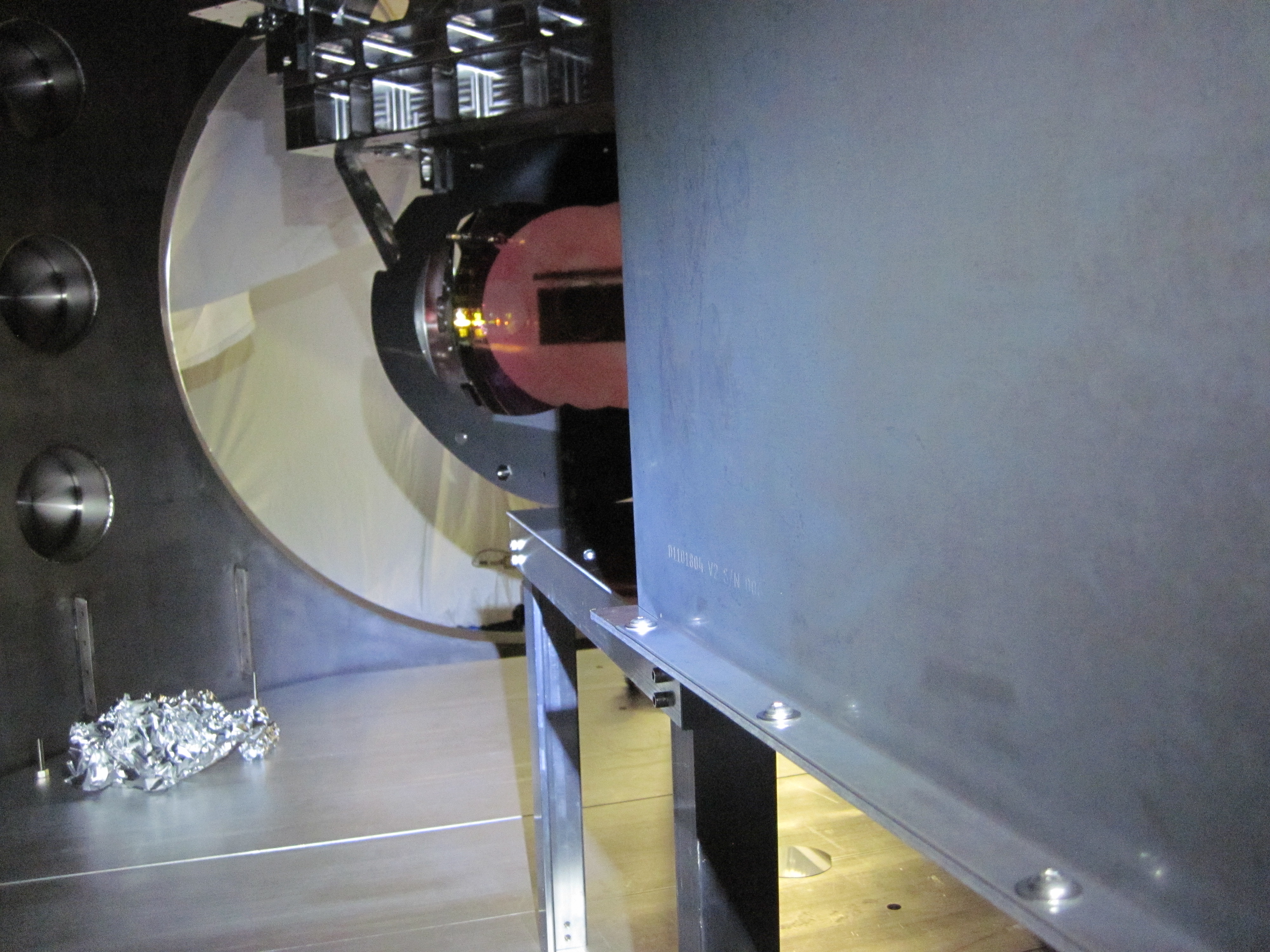
We installed a beam duct and it now connects the viewport and the enclosure hole. This is exactly the same duct style as that we installed for IOT2L. The yellow cover of the viewport was removed and put right under the HAM1 door. We didn't remove the guillotine because we didn't find the dust cover which is supposed to cover the guillotine slit when it is absent. Although we found one dust cover in the stash nearby HAM3, this looked too big. So we left the guillotine in.
ISCT1 HEPA
We wiped the interior of the table before the enclosure was moved. We let the HEPA of ISCT1 run at its lowest speed to avoid sending dusts from the inside of the enclosure. Since the enclosure is almost entirely in the clean room probably it may not need to have the HEPA running. If people think it is doing nothing but blowing up dusts we can shut the HEPA off.