dale.ingram@LIGO.ORG - posted 16:33, Friday 18 January 2013 (5164)
Friday Summary
- Apollo at EY preparing for in-chamber cleaning
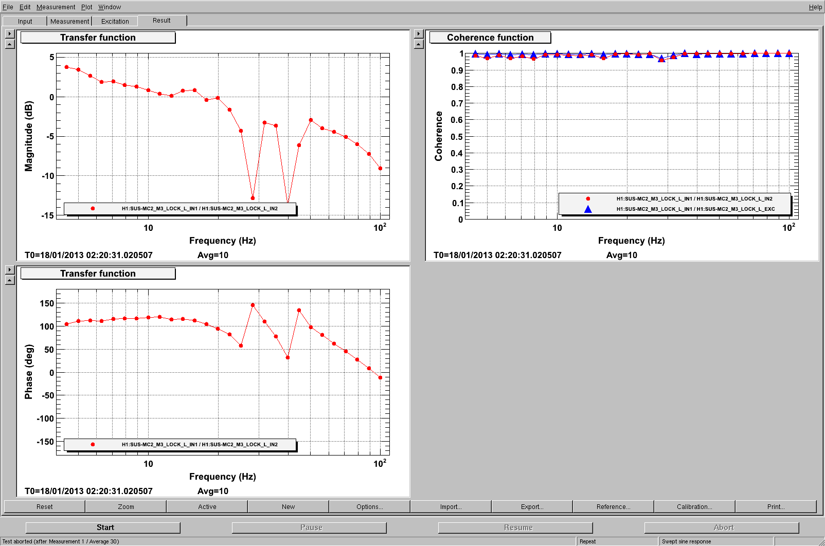
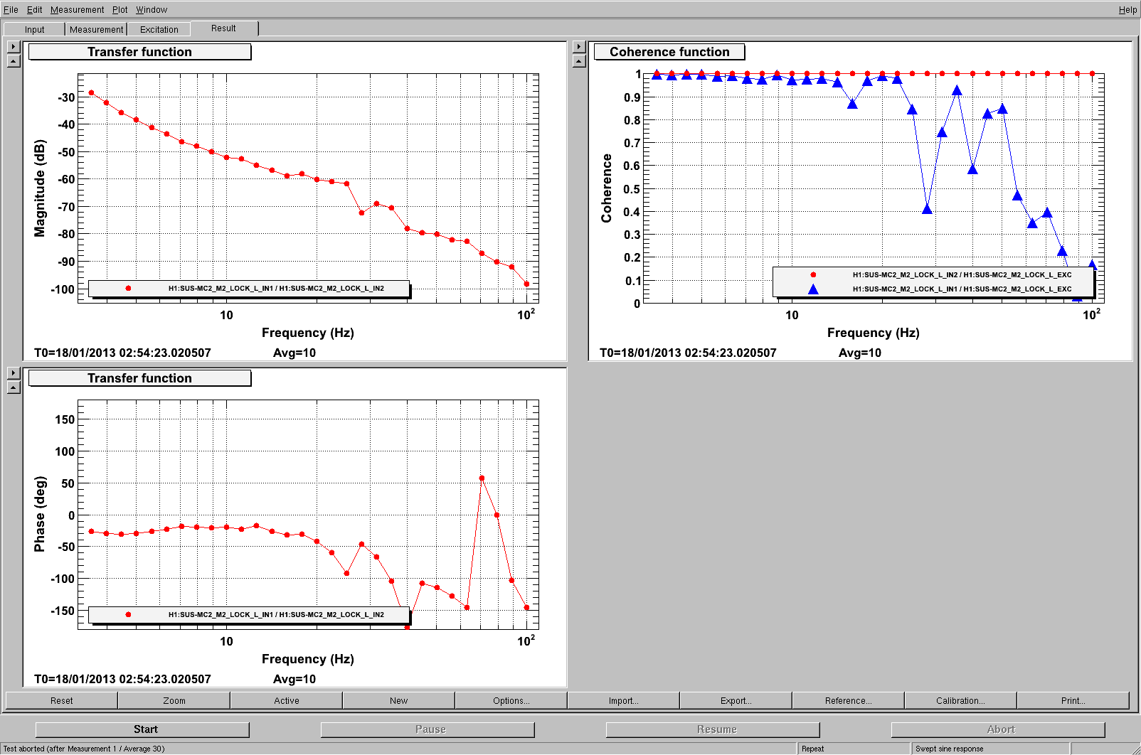
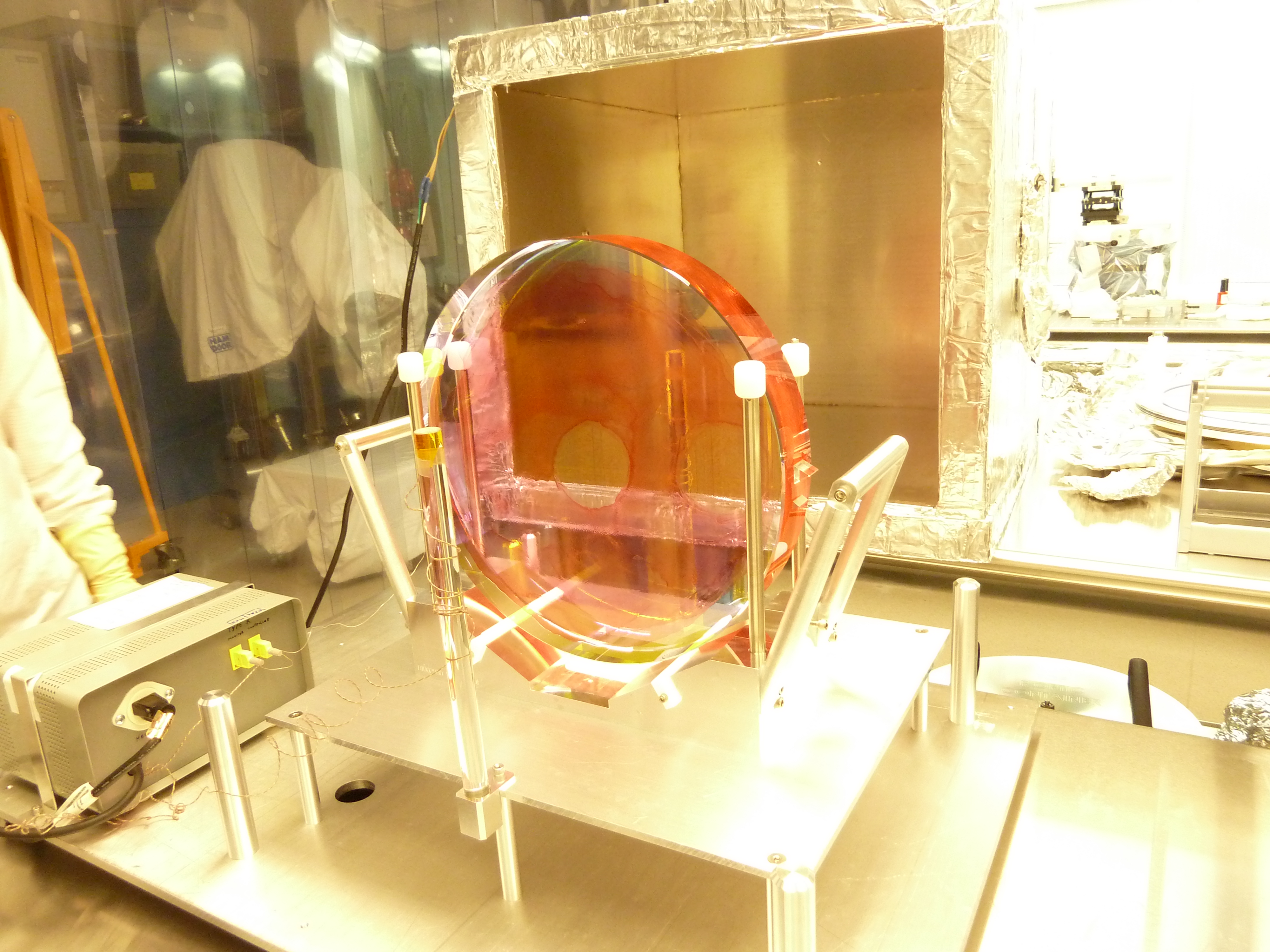
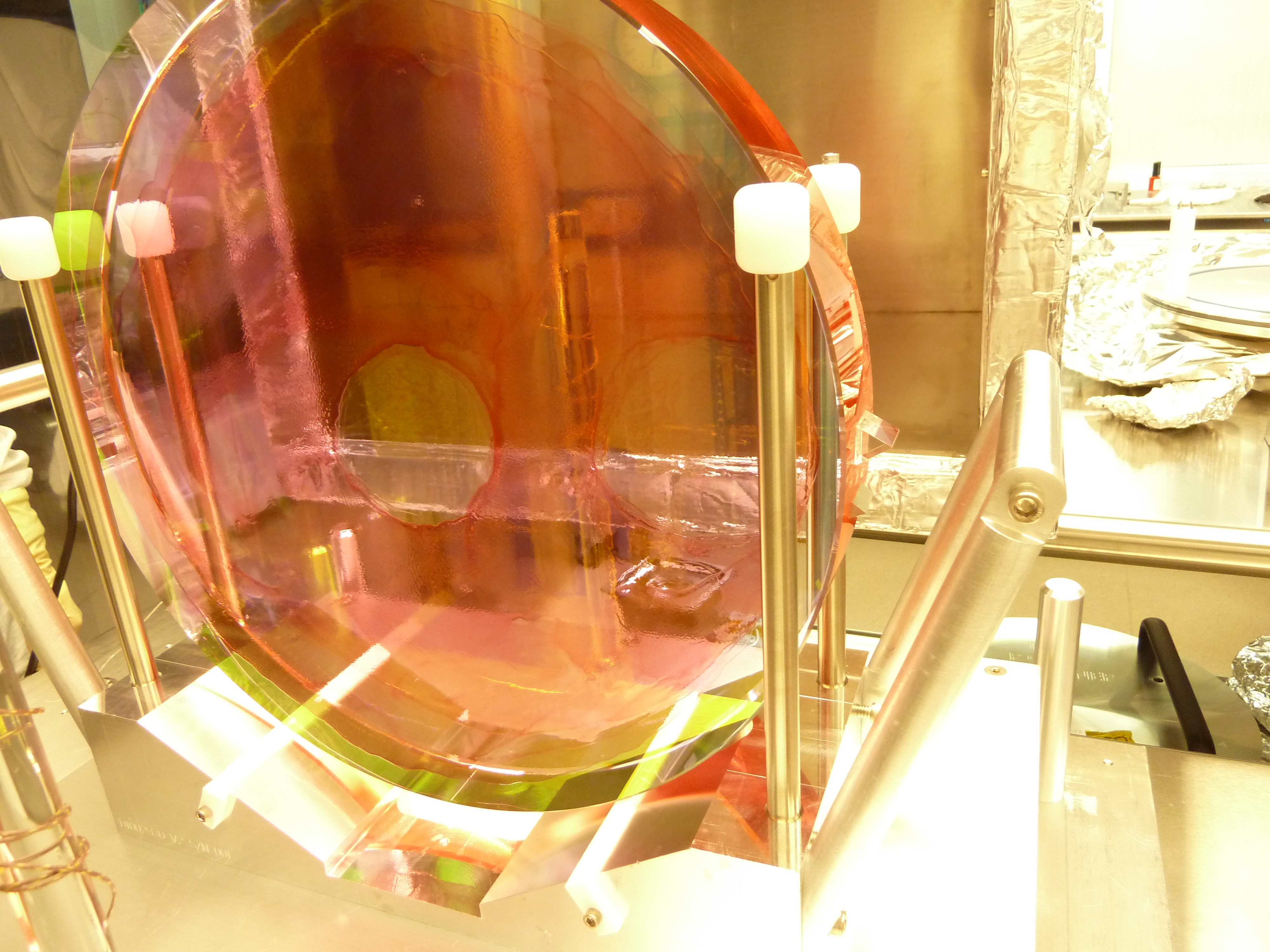
- IO team worked on the mode cleaner all day (mostly from the CR), interleaving with Hugo's ISI testing at HAM 2 and HAM 3 during the afternoon
- It appears that the mode cleaner will remain locked overnight and the LVEA will persist in modified laser safe, with the curtained area in laser hazard
- Ace serviced the portapotties along both arms today
- Alarms: Dust 15 (9:07, 10:57, 12:05, 12:09), Dust 8 (12:04), H1CDS_IOP_SUS_WATCHDOG (several between 10:45 and 12:30).
- Note the a-logs about the move of the BSC1 SUS today.
- At 16:00, the H1CDS_IOP_SUS_WATCHDOG alarm tree shows red for ITMY, SEIB1, SEIB1DACKILL, and IPC, and yellow for ETMY
- Work permits signed by ops today: 3672 (BSC1 illuminator), 3671 (BSC1 illuminator and video viewports), 3669 (SUS TF scripting), 3666 (ICC at BSC10), 3665 (leave input arm under rough vacuum, pump HAM 6 (see Kyle's entry below)).