(Corey, Keita)
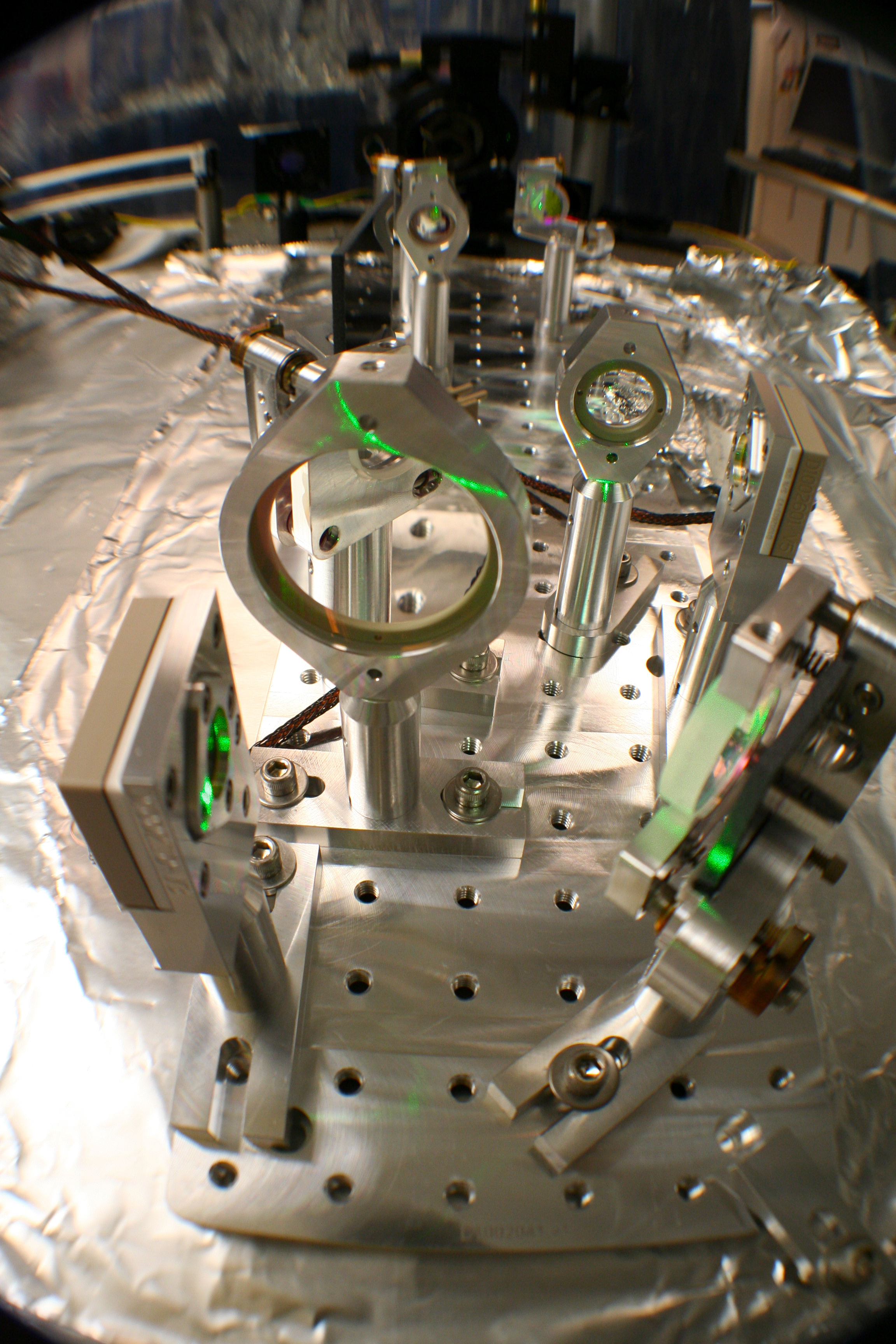
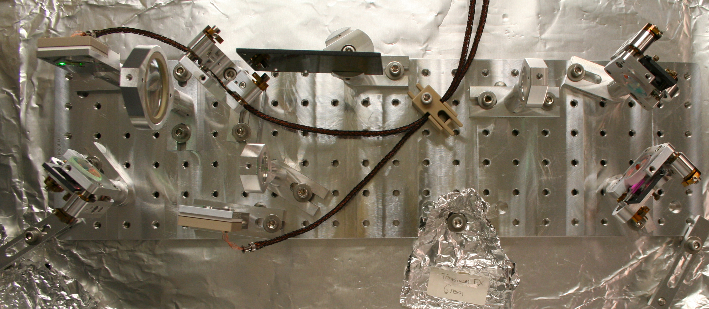
My mode-matching lessons from master Jedi Kawabe continue with the building of the EX Green QPD Sled. This Sled is one of two on EACH Transmission Monitor Suspension (TMS); the other is an IR QPD Sled (to be assembled next). We actually built this Sled twice. After completing it the first time, Keita noticed, "this sled looks like EY. It's supposed to be a mirror image!" It was all a learning experience. So, we ended up re-building the sled (it went much quicker since we, in essence, already had an assembly dry run).
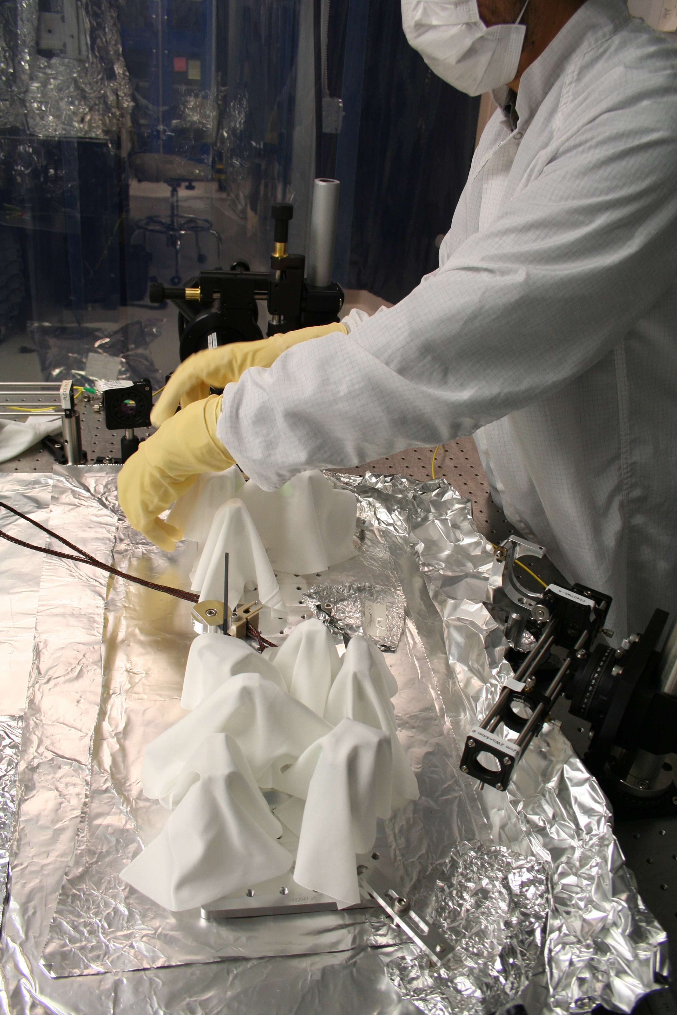
Once the Sled was completed, we draped wipes over all optical components, wrapped the entire assembly in foil, double-bagged it, and placed the entire thing in a large plastic bin for storage under our Optics Table in the Optics Lab (the HAM1WFS Sled is also stored here).
Keita has plots and data from our mode matching measurements and will post a more thorough document about our EX Green Sled work to the DCC.
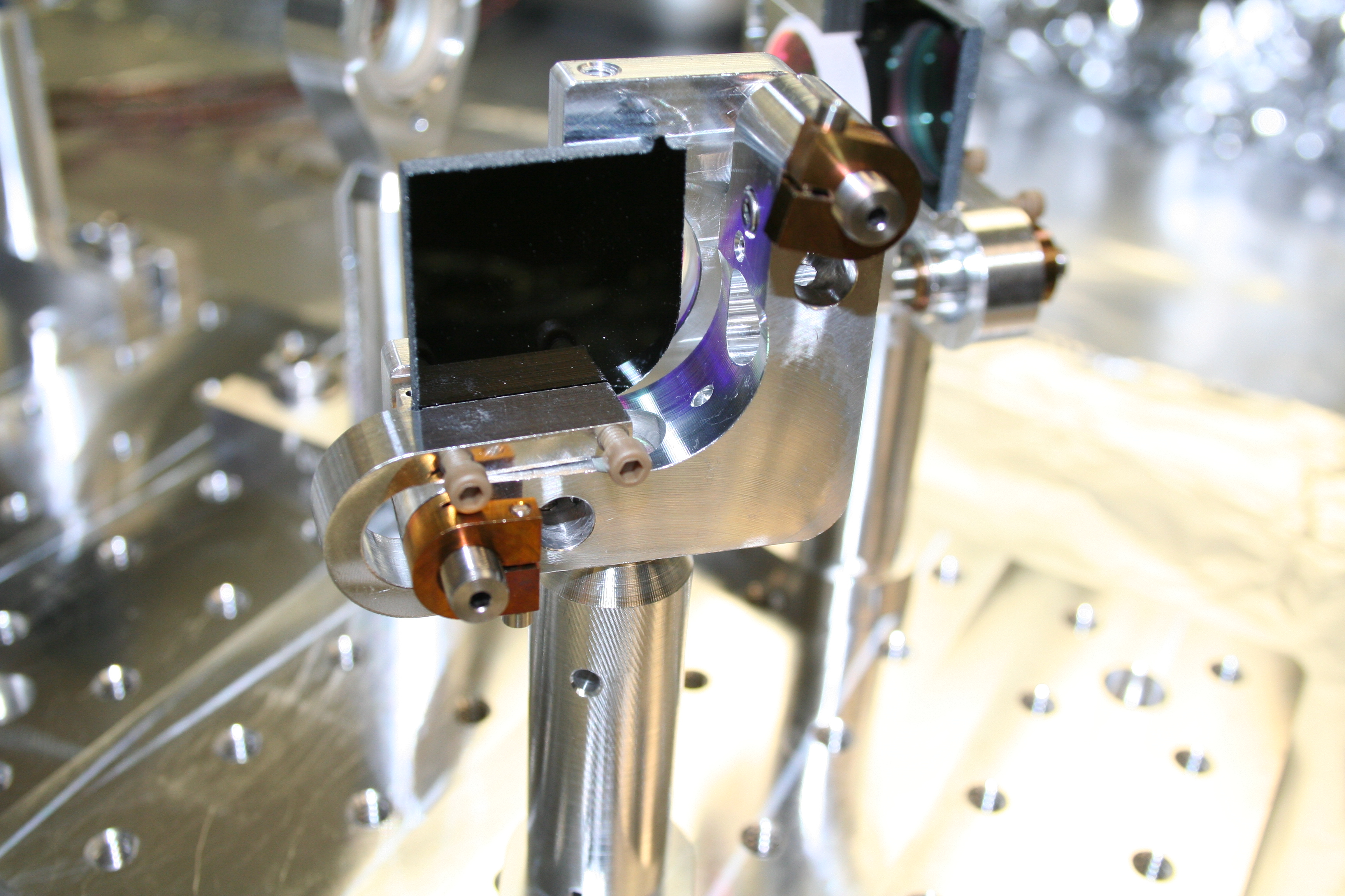
Note: The "J-Clip" Black Glass Beam Dumps on our Steering Mirrors are tough to install. There's a screw on the mount which interferes with the J-Clip and makes installing/removing these parts tough.