(Corey, Keita)
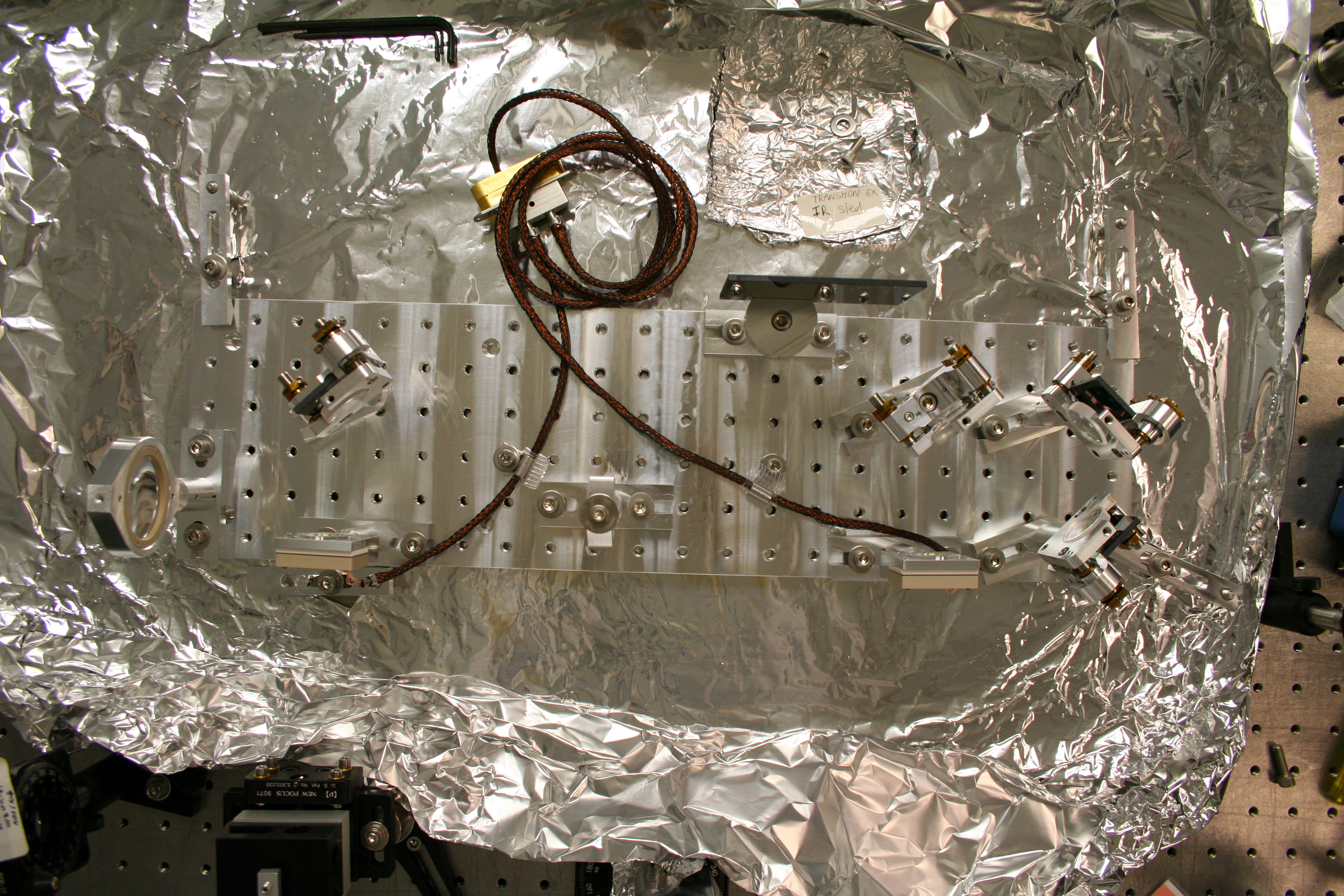
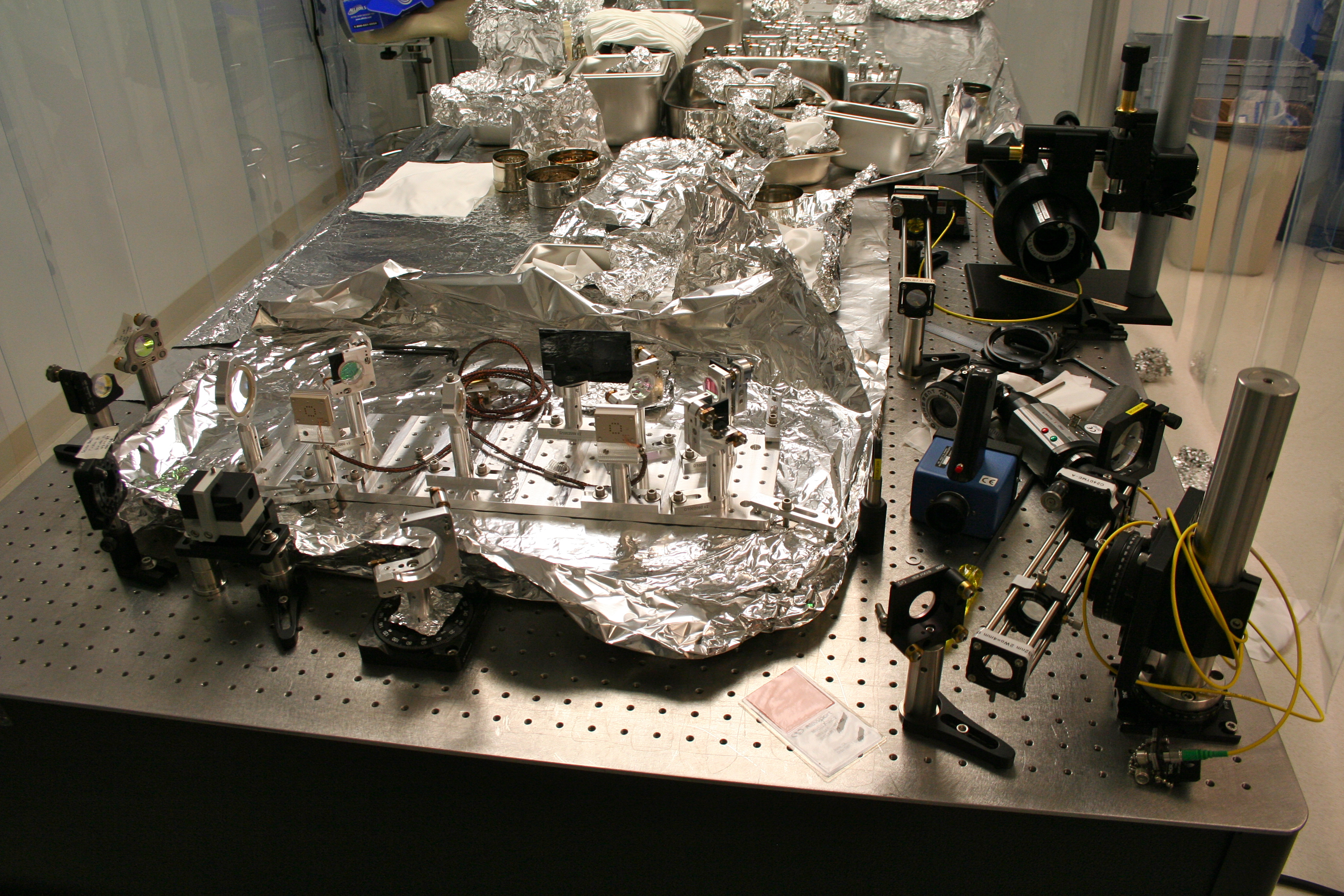
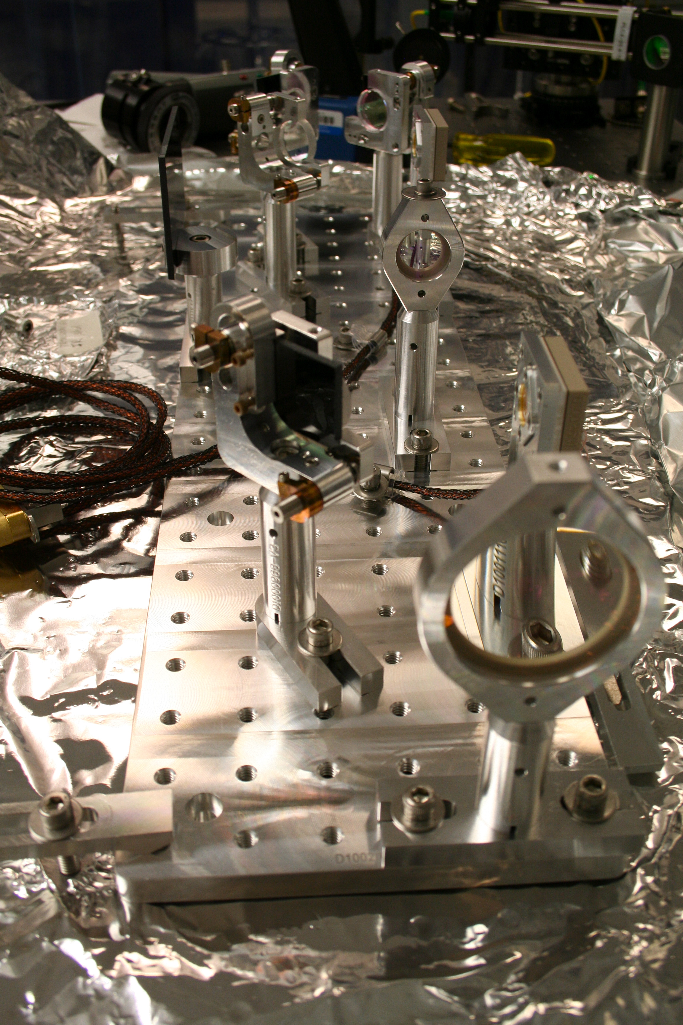
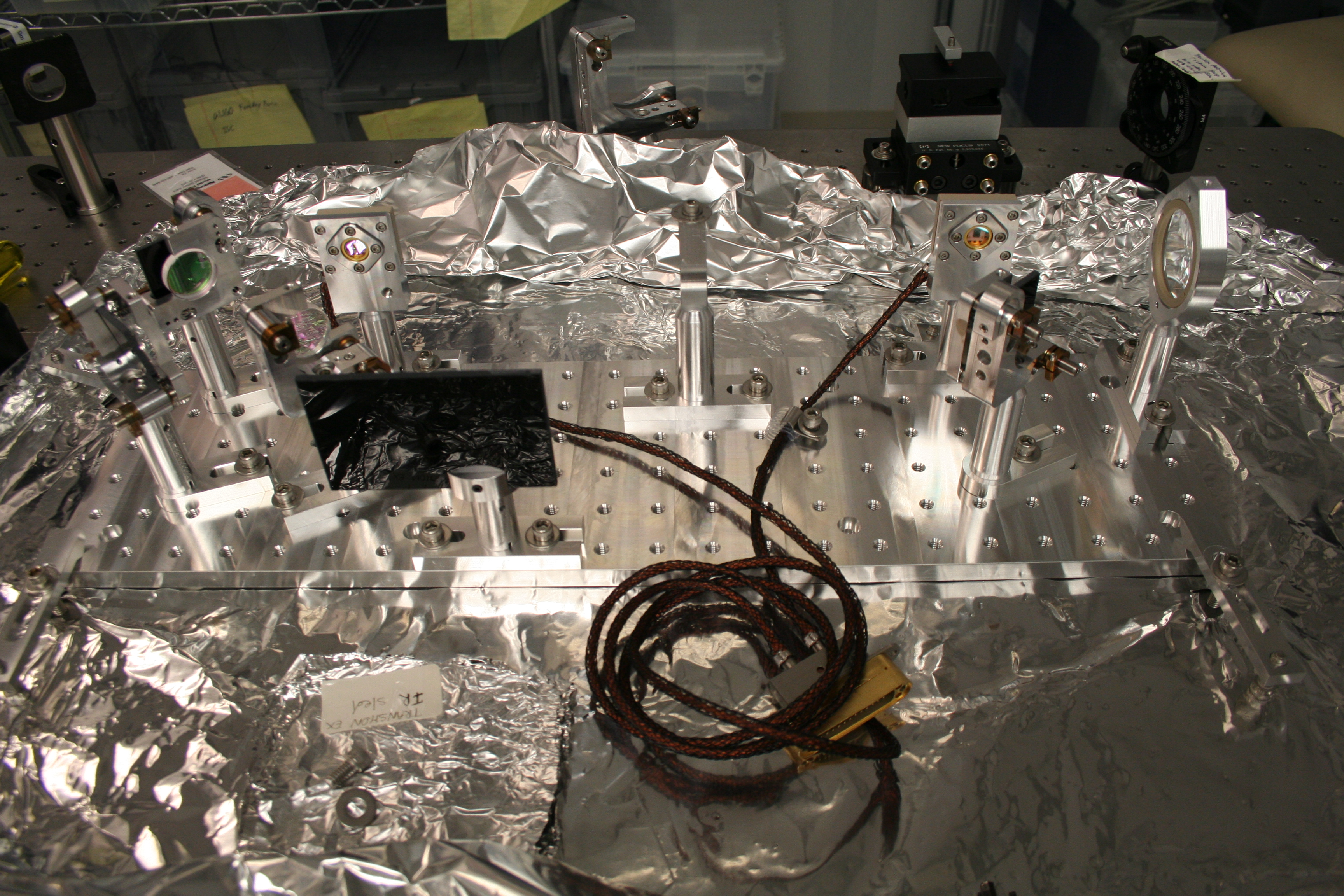
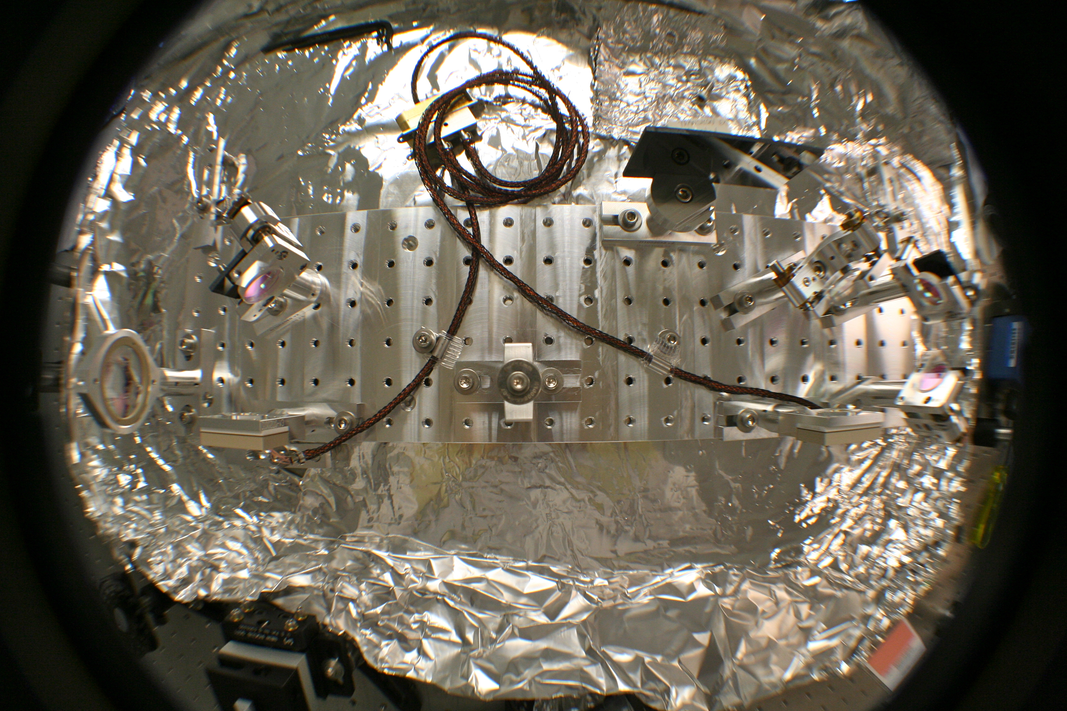
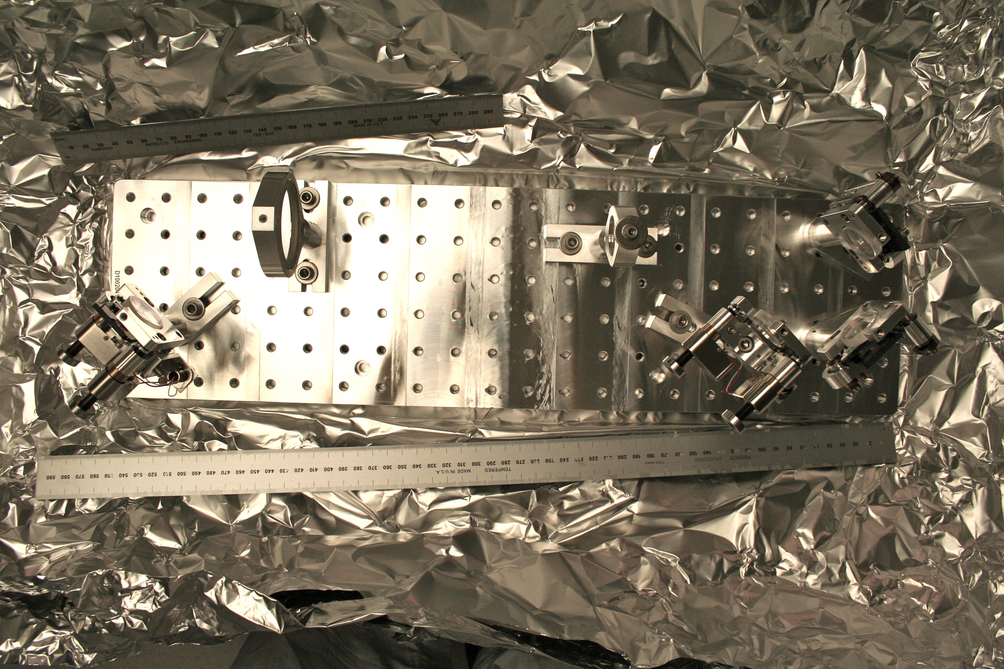
Continuing the work of building QPD Sleds for upcoming installations, Keita and I recently finished up the EX Transmon IR QPD Sled (we completed the Green Sled a couple of weeks ago; the overall Transmon document is T0900385).
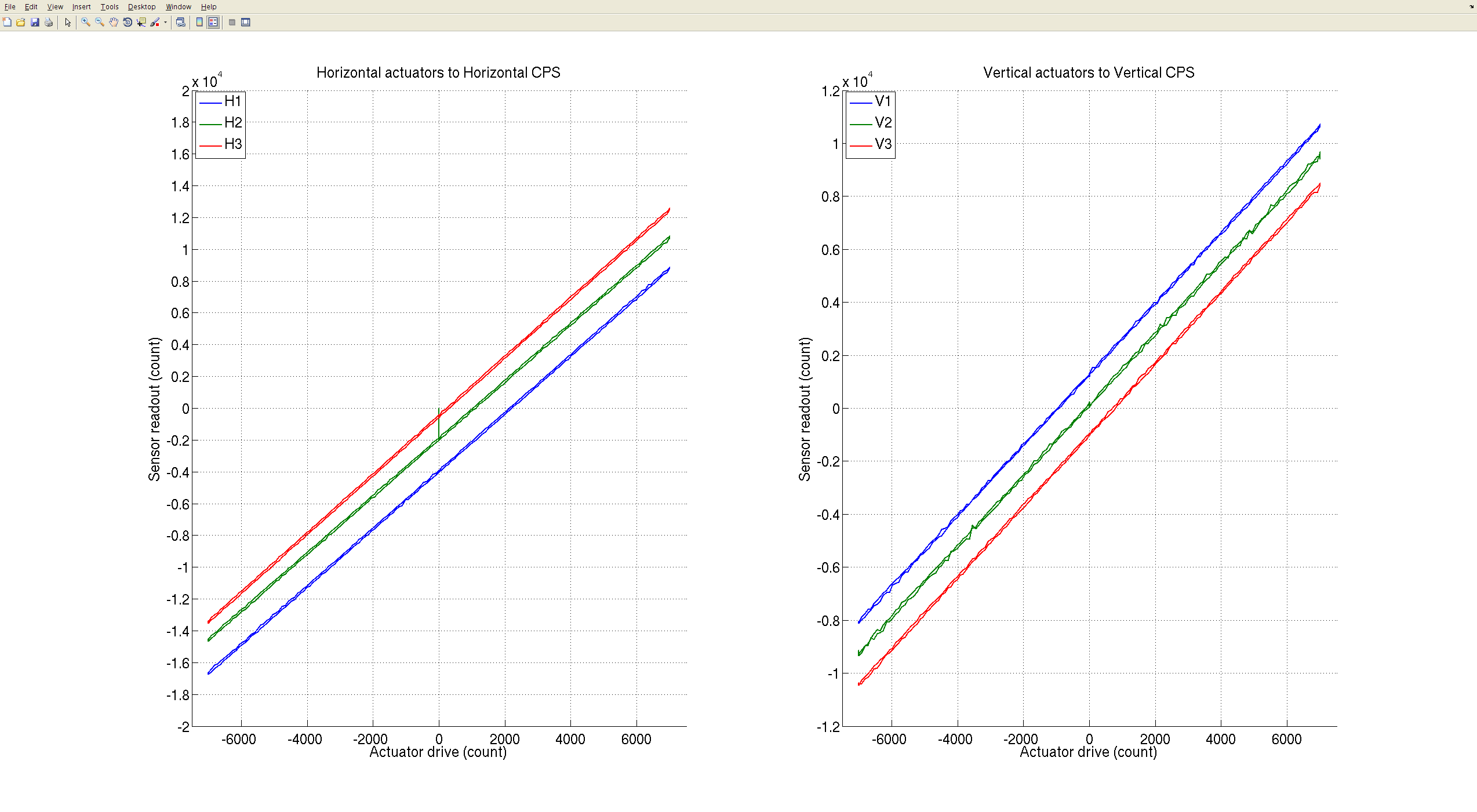
Lisa B. roughly laid out the Sled during her last visit. We then used an IR laser/launcher for our light source and worked on setting up our lenses in a way such that our beam profile would be optimized for the QPDs (Desired beam profiles are posted in the Guoy Phase document T1000247). To measure our beam profiles we used the Mode Master PC; Nicolas Smith's "A La Mode" Matlab scripting was used to calculate & plot our Beam profile. (The matlab script used for this sled is attached to this entry.)
The toughest part is setting up the Mode Master, but once it is set up, it's fairly straightforward laying out the lenses for the Sled. Once the lenses were positioned & we had our desired beam profile, the rest of the Sled optics were laid out. The Mode Master results and Matlab Beam Profile plots are attached to this entry.
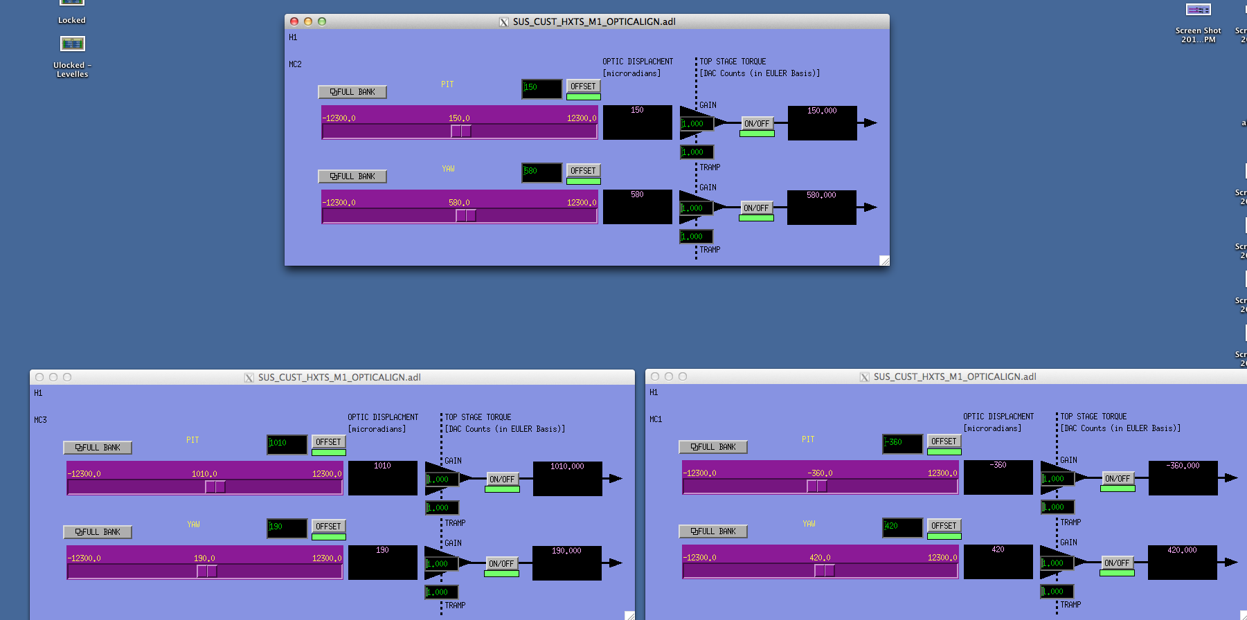
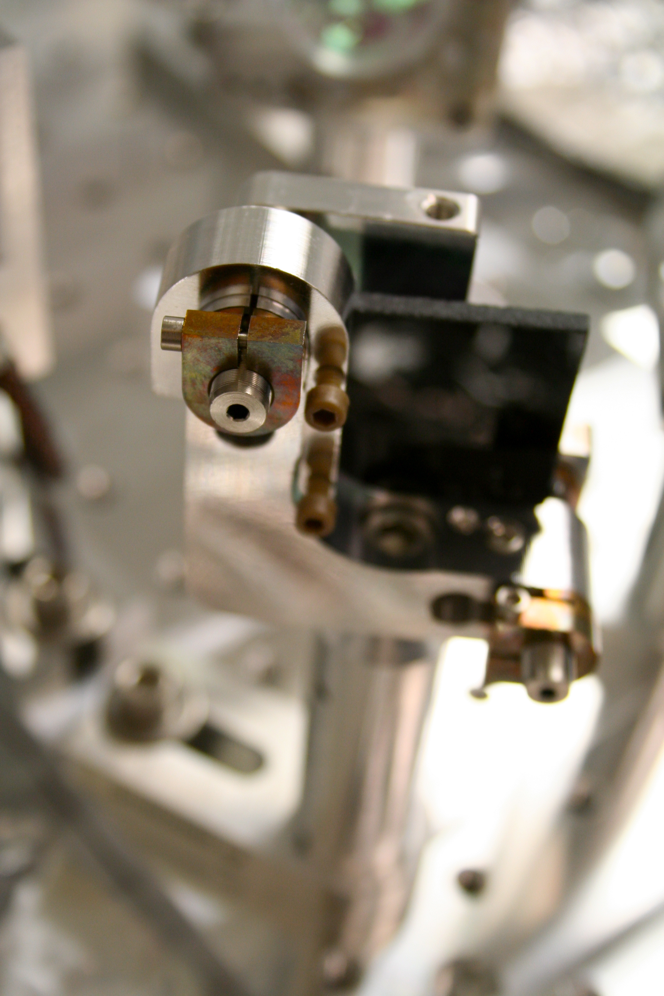
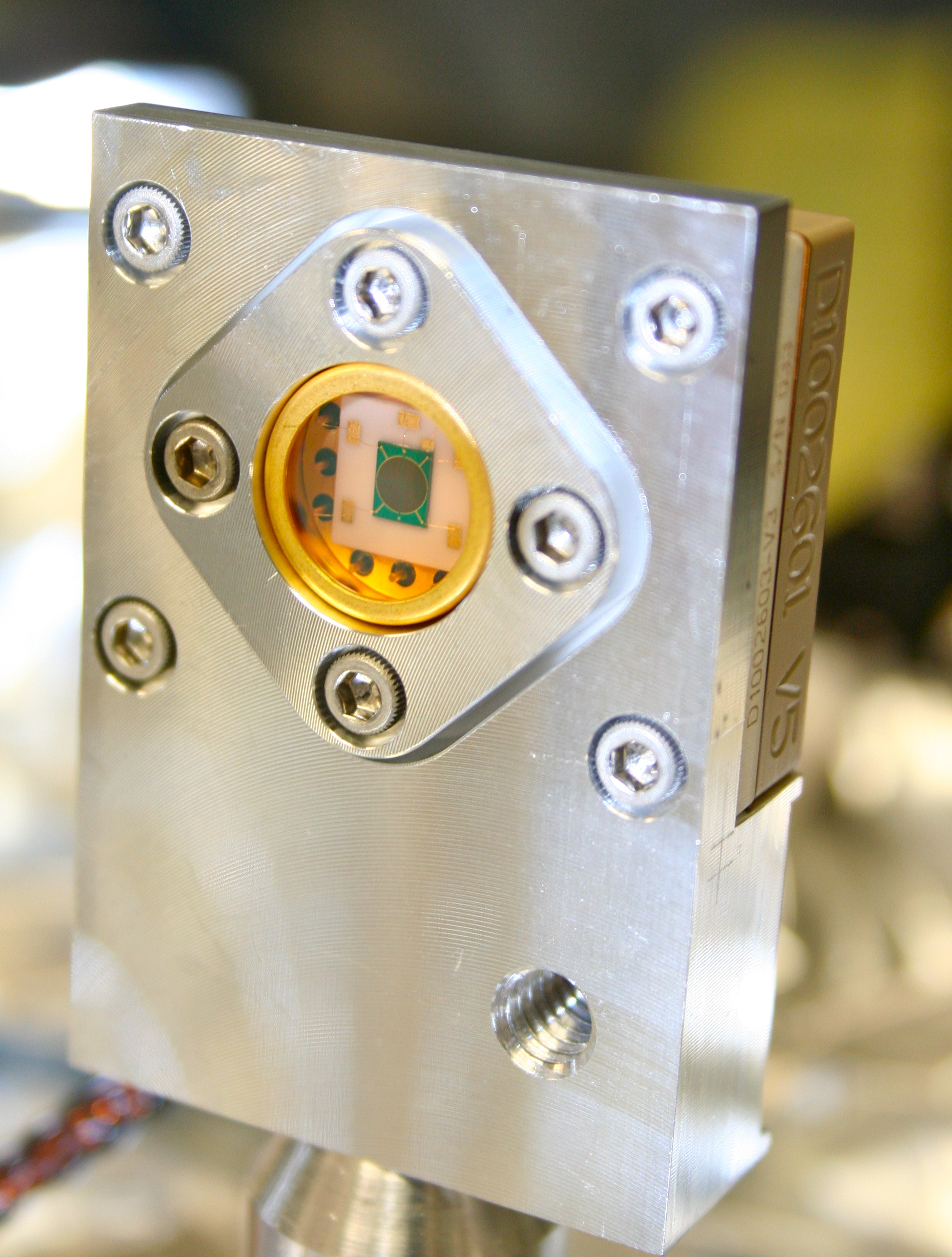
The QPDs were aligned by connecting them (via feedthrough) to a QPD LCD Readout Box, D1102092, (which powers the QPDs & has an LCD target on it). One thing with this Readout Box--make sure to have low enough laser power such that you don't saturate the Box at Low Gain (otherwise, you won't be able to center QPDs).
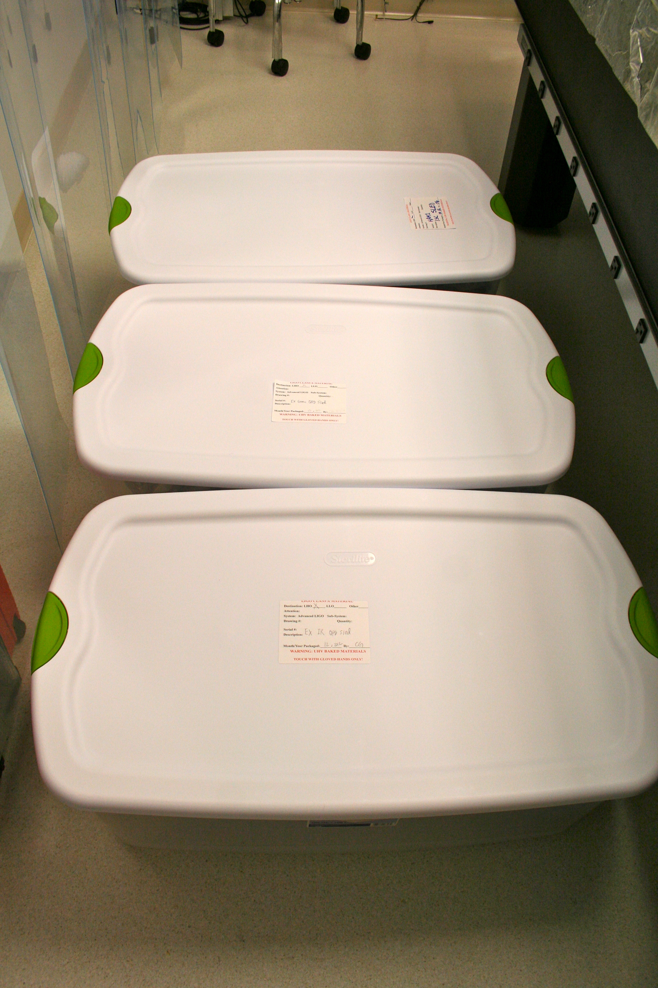
Wipes were draped over optical components, entire assy wrapped in foil & bagged, and is now stored in a plastic bin. This bin will be stored in the Optics Lab under our Optics Table until we are ready for installation. Keita will submit an a document about this Sled to the DCC separately.
Below are documentation notes for this Sled.
Optical Component Distances
For measurements below, the lenses are measured on the "backface" of their Lens Holder. The Mirrors & Beam Splitters are measured from their glass "front faces". Measurements were measured with a scale & all measurements are in mm.
-
L1 to L2 = 236
-
L2 to SM1 = 236
-
SM1 to SM2 = 46
-
SM2 to BS = 63
-
BS to QPD1 = 63
-
BS to SM3 = 304
-
SM3 to QPD2 = 67
Photographs
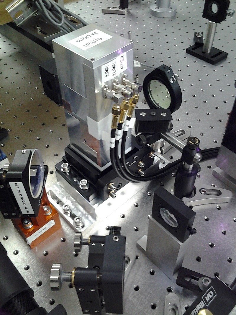
Several of photographs of the build for this Sled are attached to this entry, and ALL photographs are posted in ResourceSpace, here.
List Of Components Installed
-
(6) D1002059 ISC Mounting Base-Double
-
(3) D1002060 ISC Mounting Base-Single
-
(4) D1001116 ISC Mounting Post 1-5/8"
-
(5) D1000968 ISC Mounting Post 2-1/8"
-
(4) 1" Right-Handed Siskiyou Mirror Mounts
-
(1) D1102166 ISC 2" Fixed Optic Holder & Peek Retaing Ring
-
(1) FOH-1.00-VC ISC 1" Fixed Optic Holder & Peek Retaing Ring
-
(1) E1000845-07 1" f= -111.2mm Lens
-
(1) E1000845-10 2" f= +333.6mm Lens
-
(1) E1000671-01 1" 50:50 Beam Splitter
-
(3) E1000969 1" High Reflector
-
(3) D1002701 Mirror Mounted Black Glass Clip w/ black glass
-
(3) D1100044 1" Mirror Mount Black Glass
-
(1) D1000972 V-Holder for Black Glass Beam Dump
-
(1) D070476 Black Glass Small, Left
-
(2) QPDs (custom cable S1202411)
-
(1) D1002041 ISC QPD Sled (breadboard)
-
Miscellaneous bolts, washers, etc.