We finally swapped the M3 stage UL AOSEM which had a cracked filter (s/n 242). The new unit (s/n 212) has an OLV of 26640. Stuart reset the PR2 M3 UL OSEMINF offset to -13320 and the gain to 1.126.
As per Travis' alog yesterday, we indeed did hop into BSC8 this morning and finish checking and stowing the FMy and ITMy suspensions. We put C3 socks on each. Travis then started detaching the SUS cables at the internal feed-thrus.
Restarted h2 data concentrator to add h2isitst channels at 10:53 PDT. The daqd process on h2nds0 failed to restart, so I started it manually.
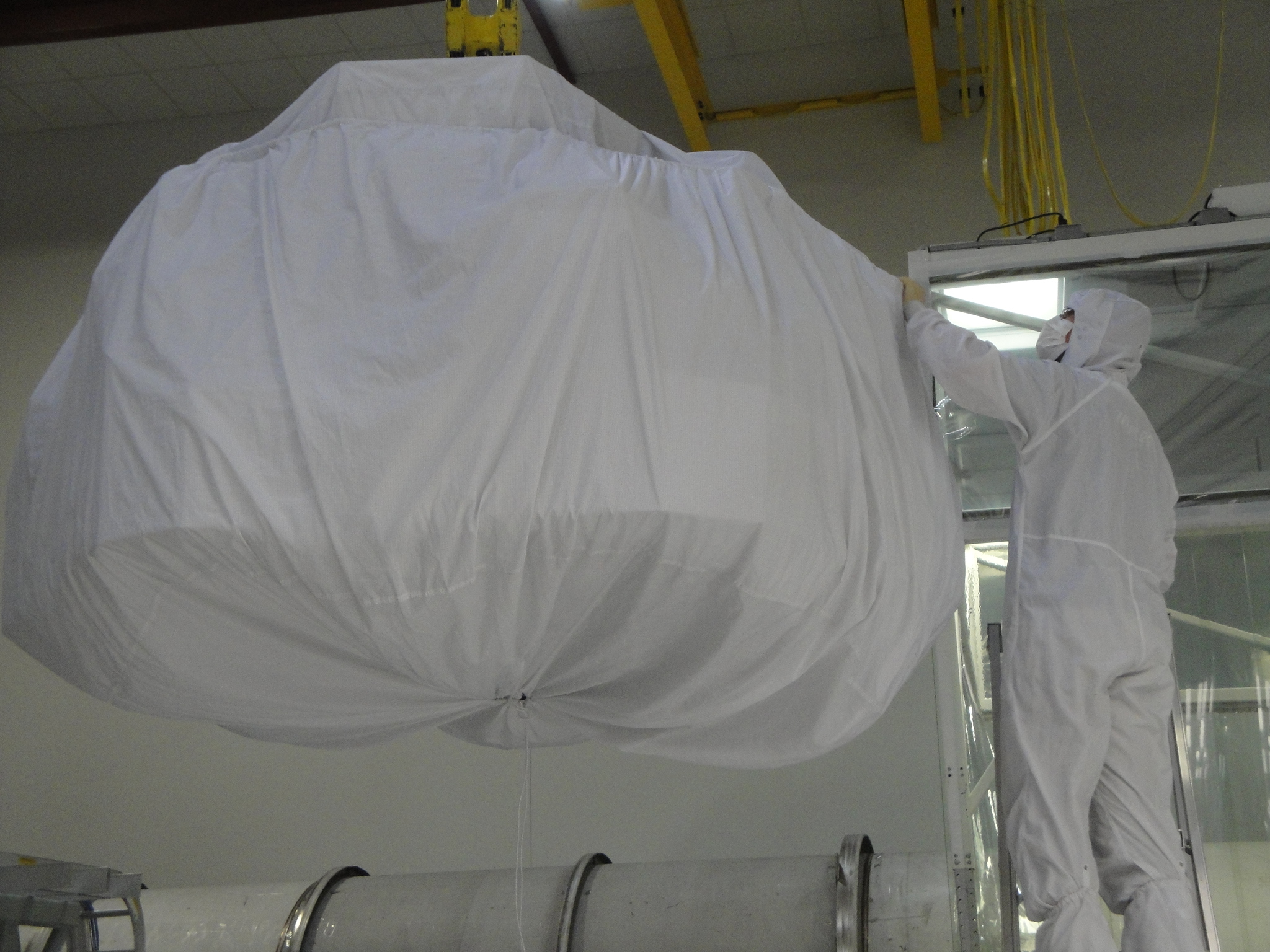
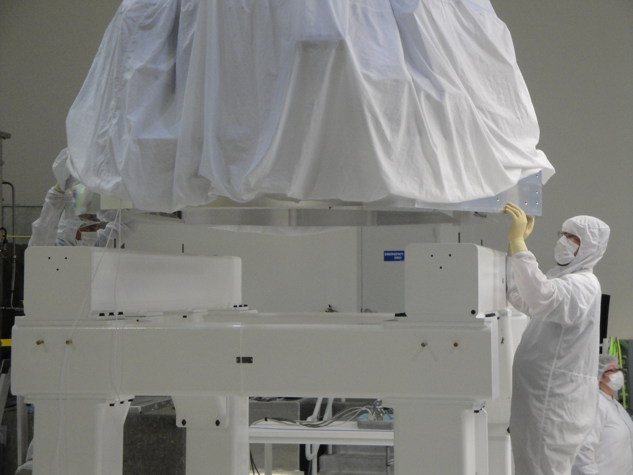
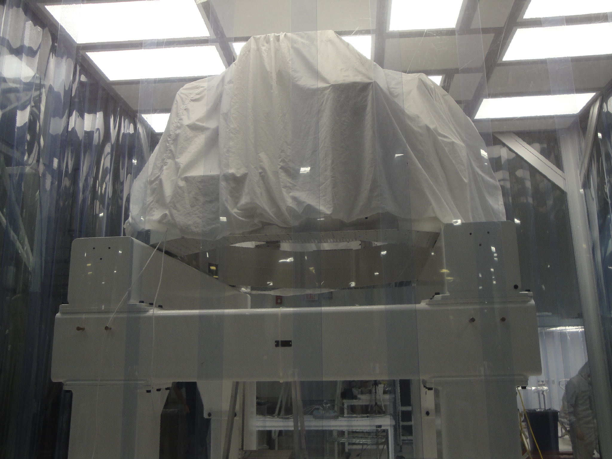
On Friday, 28 Sep, the cleanroom was rolled to the north, then the solid stack was craned off the test stand and preserved clean. This morning, the test stand was wiped down. After lunch, the cleanroom was moved back over the test stand: the cleanroom/test stand and general area will be cleaned in preparation for the cartridge. After some examination this morning, I was able to improvise both garbing and staging space in the iLIGO cleanroom atop the e-module. Jim Warner was instrumental in carrying out the plan. Apollo craned garbing/staging accoutrement to the e-module and things are close to ready.
- SEI work at input HAMs - Ken at X-end - Apollo installing ladder on mezzanine - Vincent install a test model on the BSC8 Test Stand - Cleaning of the optics table in Squeezer area
Both the ITMy and FMy suspensions in BSC8 have been fully locked down for transport, with the exception of the vibration absorber locker pins on FMy. Optics caps are on both the ITM and TCP exposed faces and the inter-chain temporary transport stops (fingers) are in place. On Monday, I will have Betsy take a second look and add any additional protection and C3 covers to the structure deemed necessary. We should then be ready to proceed with ACB deinstall, decabling at the feedthrus, and SEI offloading of mass in prep for cartridge extraction.
35W beam. Fans were on during these measurements.
Jim went into the top cleanroom at BSC8 and locked the ISI down after landing ISI#3 on the Test Stand Thursday afternoon. SUS is free to lock away. HEPI was locked down some time ago so SEI is fully locked down.
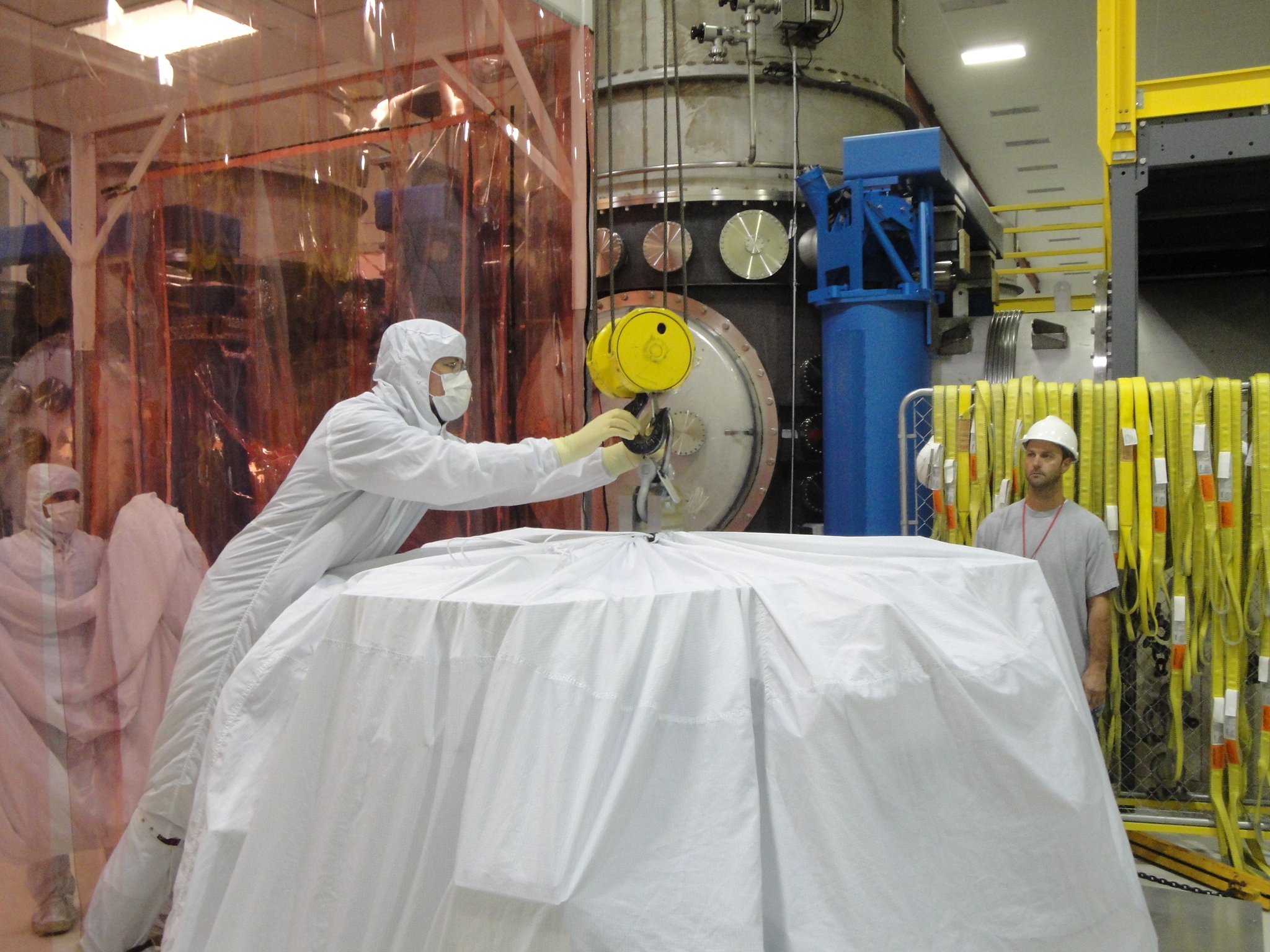
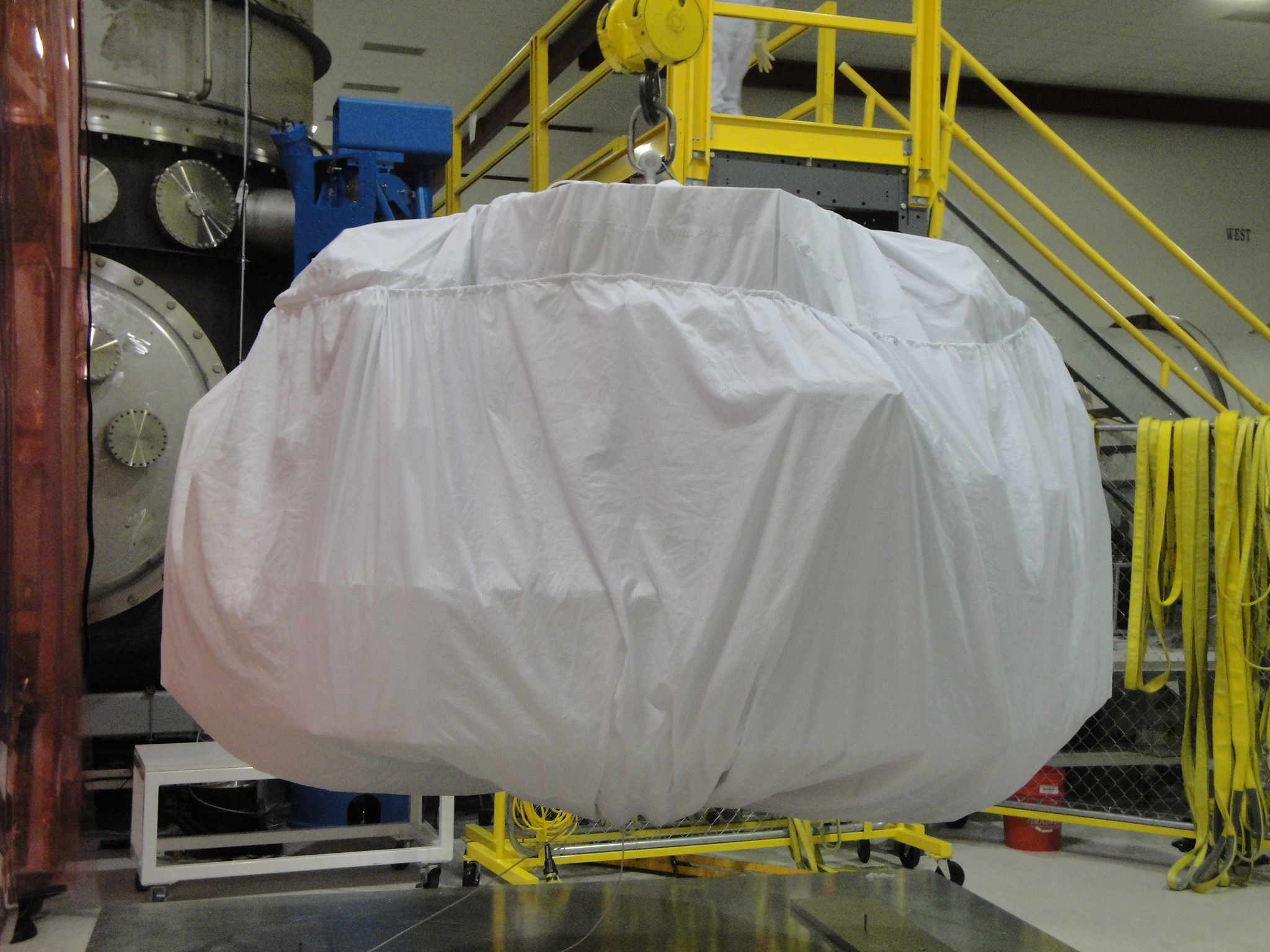
The Assembly crew, Jim Greg & Mitchell, completed the installation of instruments and sensors and prepped the unit for craning to the Test Stand Wednesday. It launched right after lunch Thursday and other than a sticky spot in the crane travel, landed with no issues. Thanks to Bubba Randy Mark & Jody for excellent assistance.
After 2 hours and at least 48 picks with the manual Genie fork lift (including forks on, forks off, forks on, forks off, repeat) we finally got the BSFM02 out from under the solid stack/test stand and into it's storage container. Those darn test stands just aren't roomy enough or tall enough for easy SUS maneuvers.
The storage box is still parked in the cleanroom since we need to add a gasket to the door for proper sealing. It is sitting to the North with all of the other tables such that the cleanroom can be pushed North to facilitate removal of the solid stack.
For the record, the Top BOSEMs and Top BOSEM cables are still attached to the suspension. Also the shear plates were installed this morning and are with the sus in the box. All parts are recorded in the assembly record for BSFM02 (under D1000392) in ICS.
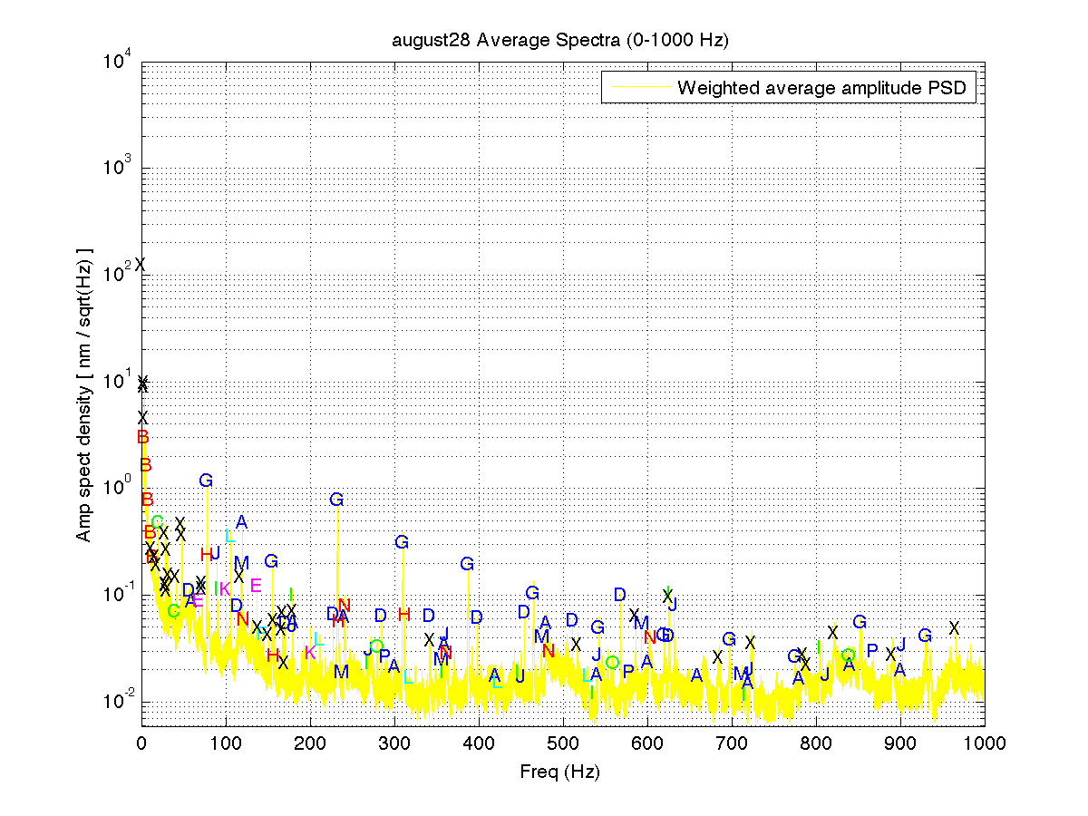
Following up on the earlier post 3646 concerning H2 OAT line studies, I am attaching some slides extracted from a detchar report at the Rome LVC meeting, with some new, additional plots and tables based on further analysis. To make future alog searches for frequencies easier, below is a cut n paste of the final table of known combs and individual lines. Comments:
Attached are plots of dust counts > .3 microns and > .5 microns in particles per cubic foot.
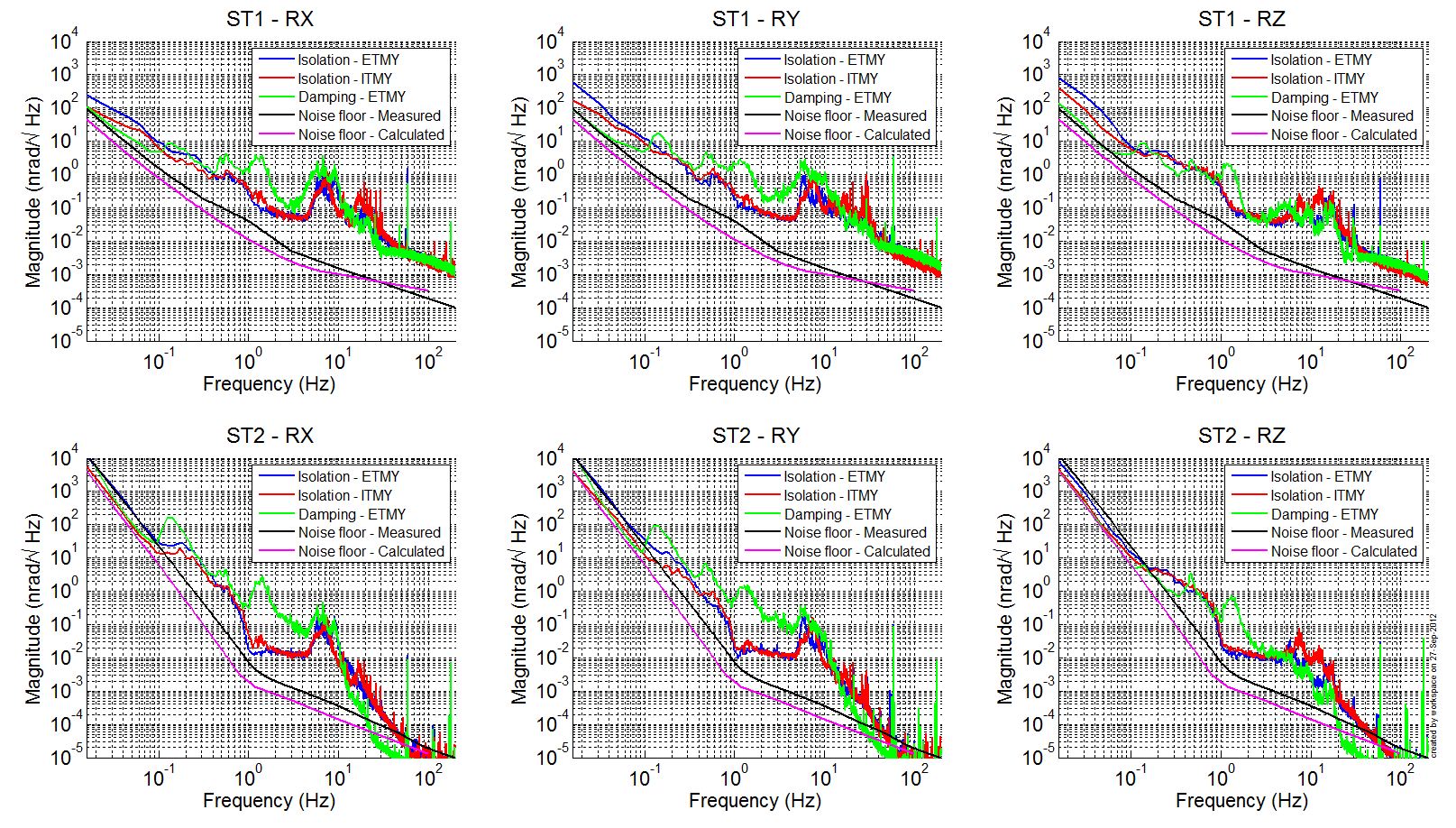
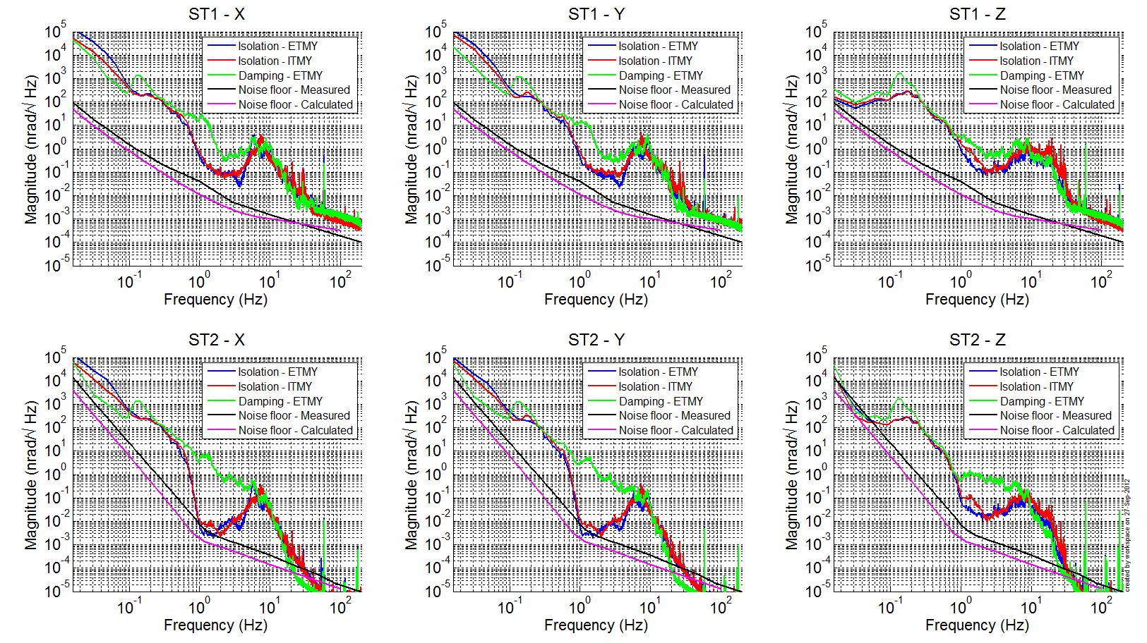
In attachment, spectra of the geophones installed in BSC6 and BSC8 are presented with their noise floor are shown in two configurations:
- ISI damped (only BSC6)
- ISI controlled (L4C blend at 250mHz)
Below 100mHz, in the case of the damping, T240s are in their noise floor for the rotation DOFs and largely above their noise floor for the translation DOFs. GS13s installed on stage 2 are in their noise floor for all DOFs. Consequently, it is difficult to evaluate the actual amplification of the absolute motion of the optical tables between the damped and the isolated configuration. The amplification might be higher than 10, maybe 50?
At EY, when the HEPI-ISI isolation filters are engaged, the optical levers are seeing mainly translation of the test mass and amplification of the "apparent tilt" in pitch and yaw is 50.
Three-point spreader and walking plates finally made it from Y-end to the corner in the horse trailer. Both items got a good wipe down and were used today. The walking plates were installed by the Apollo crew (Randy, Mark, Scott,Eddy) so that work can begin at the BSC dome flange height. I went into the chamber to retrieve witness plates late this afternoon. We'll look at them when we get a chance.
Mark B. Trying more BSFM02 TFs with higher drive levels for better coherence and slightly reduced gains copied from L1 (as optimised there by Anamaria). If the suspension starts getting dismantled in the middle of it, too bad, so sad.
Mark B. Got L and P data and then the suspension went away.
The Apollo crew worked on the following: craned one aLIGO garbing/staging cleanroom from the beer garden to the south side of BSC8; craned an iLIGO cleanroom from by HAM6 to the E-module; removed BSC8 south door; retrieved walking plates and three-point spreader from Y-end; and located bang boards for cleanroom use. Karen and Cris cleaned both garbing/staging cleanrooms. I staged a few things (garbing rack, staging table, foil, etc.) in the lower level cleanroom.
Walking plates and three-point spreader did not make it to the corner after all. >-(
35W beam. The laser room HEPAs, lights, and AC units were turned off and the make up air was set to 50% for these measurements. The anteroom lights and HEPAs were still on.
Pointing file didn't upload, I attached it here.
This was supposed to be posted by me...
B. Bland, J. Garcia, J. Kissel Attached are plots comparing the recent H1 SUS PR2 Phase 2B measurements against other HSTS in various stages (completing the data package) in order to give a final answer on Phase 2B testing. As of this entry H1 SUS PR2 passes Phase 2b and is go for install into HAM3, with the following caveats: (1) Late in the game, the assembly team found an IR filter is missing on an M3 (Bottom) stage AOSEM. The spectra comparisons show that there's little-to-no difference in the response of sensor, i.e. it's functional (as far as you can tell in the noisy chamber-side environment). Regardless, the assembly team are aware of the problem, and will replace that AOSEM once in chamber, as there's plenty of room to play around in there, and it's a simple fix. (2) It's a long story (so I'll save it for a subsequent comment to this log), but we discovered the same small T to Y cross-coupling at 1.1 and 2.05 Hz on PR2 as was recently discovered on X1 SUS MC3. At the time, (we thought) X1 SUS MC3 was the only SUS that had such cross coupling, and (we knew we) still had lots of chances to debug the issue before install, so we approved his Phase 1b results and agreed to move forward. However, due to the hectic/scattered measurements and turn-on blips of getting the HAM SUS up and running at LHO, the cross coupling in H1 SUS PR2 (formerly X1 SUS PR2) has fallen under the radar up to this point. So, in light of several things: - (As in seen in the attached TF comparisons, specifically pg 2, the M1 to M1 T to T TFs), ONLY X1 SUS MC3 and H1 SUS PR2 show this particular cross coupling, out of Nine other HSTS that have been built project wide (again further clues, a better zoom, theories, and conjectures to come). - We will move X1 SUS MC3 chamber-side, and the install team will spend an extended amount of time identifying/debugging the problem where there's plenty of room, and less pressure. Once the problem is solved, they will retroactively make the same changes to H1 SUS PR2 in chamber, where (at least in HAM3) there's a comfortable amount of room to make adjustments. - Again, the coupling is small, and goes away with damping -- the concern is the model, which we use extensively to predict motion estimates, may not be as accurate. Ease of later documentation, the individual measurements that compose the rest of the package are aLOGged here: Damping Loops OPEN M1 to M1 TFs: LHO aLOG 3851 Damping Loops CLOSED M1 to M1 TFs: LHO aLOG 3855 Amplitude Spectra of All Stages: LHO aLOG 3861
M3 stage UL AOSEM swapped. See this alog:
https://alog.ligo-wa.caltech.edu/aLOG/index.php?callRep=4338
I'll back log that we also straightened the side flag mount in an attempt to reduce cross-coupling noted in Phase 2a/b testing earlier. We released the masses into suspension and Stuart ran TFs last night.