michael.rodruck@LIGO.ORG - posted 15:37, Wednesday 20 June 2012 (3187)
PSL plots
35W beam
Non-image files attached to this report
35W beam
After Jeff G made his changes to the h2susetmy model to ingest the Optical Lever quad photodiode signals from the second ADC, we experienced strange "DAC channels already in use" errors between h2susetmy and h2sustmsy. We checked the models carefully, no conflict was apparent. I have recompiled (but not installed) all H2 models this morning against RTS Tag2.5, so I suspect I was the cause of the problem. I rebuilt all models on h2susb6 against the Tag2.5 and the suspensions for ETMY and TMSY are now working.
200W beam
After a serious round of fit checking on Monday (going through the motions on the wrong optic), Danny yesterday in my absence glued the first primary prism onto MC2. It cured at room temperature overnight. The fixture was removed this morning and the prism is now under a heat lamp cure until ~3pm this afternoon.
The setup for the fixture which requires the ability to use a horizonally mounted height guage is still flat out dumb. After ~7 mods to parts, I've recreated Danny's setup at LLO (kudos for getting the poor design to work at there!), but we still find that the multlitude of bolted together stages do not hold the long lever arm of the height guage steady enough. As well, we are still hand pushing the jig fixture around to acheive the 0.1mm tolerance on the placement of the prism (no micrometers!!). I do not see how we can continue to use the exsisting fixtures for 13 more optics (H1 and I1), without sacrificing serious efficiency (and my mental health). So, I'm going to try the iLIGO gluing fixture on a spare optic, in parallel with fussing through the cobbled together setup we have now for the 2nd MC2 prism.
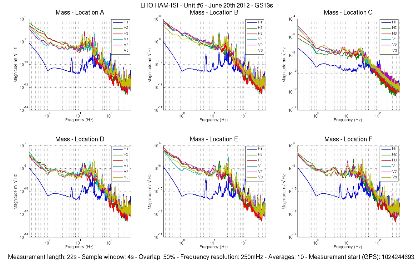
Part of the Assembly Validation testing of HAM-ISIs (that happens in the staging building) consists in taking power spectra with the ISI tilted. It allows us to check that the sensors, especially the seismometers, work in tilted position as well. To do so, spectra are taken with a 10kg mass set at each of the 6 corners of the optical table (Locations A to F in ISI_Tilted)
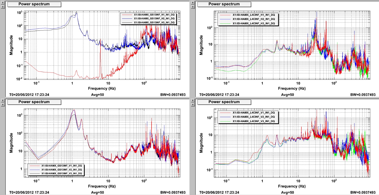
This test revealed that GS13-H1 (Pod #94) was not functioning correctly. Symptoms are the same as observed on previous failing GS13s. The response of the instrument drops dramatically below 60Hz (ISI_Not_Tilted) which is characteristic of a stuck seismic mass.
This instrument was tested OK at reception from LLO. It is very likely that the tilting of the ISI induced the sticking of the seismic mass.
We have one last spare horizontal GS13 (Pod #18). It will be installed as replacement today. Testing of this unit will start over with sensor spectra, as soon as it is installed.
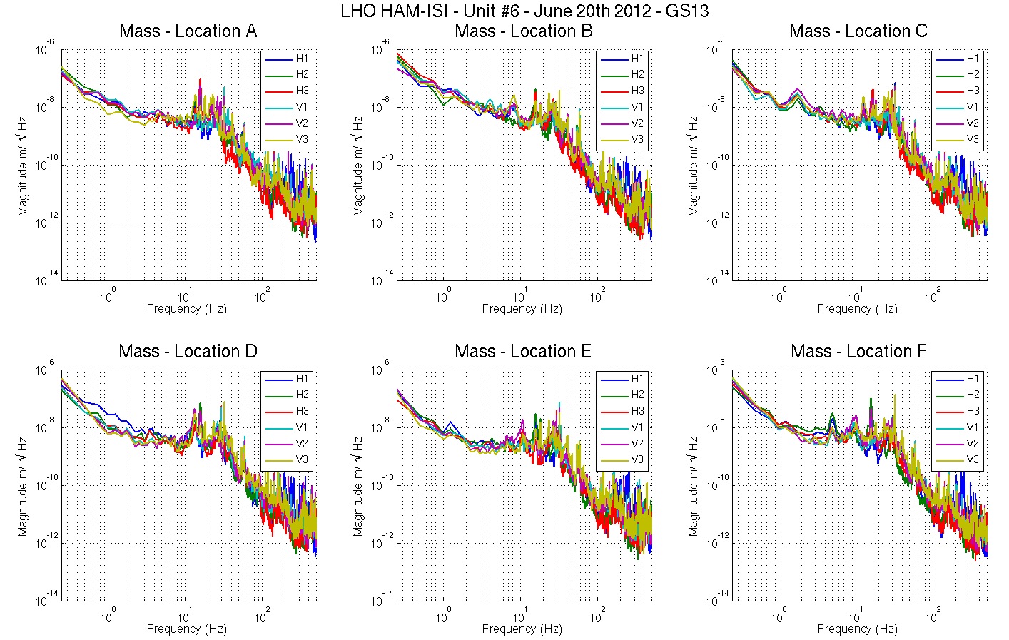
GS13 pod #18, installed as replacement for Pod #94 on H1, appears to be working correctly, even with the ISI tilted.
This pod, and the one it replaces, both come from the same shipment.
Spectra are attached
Mode Cleaner Tube baffles in MC1 installation alignment was verified as accurate for both MCA and MCB ends.

MCA1 - Fasteners were loosen to reposition center plates. The missing center clip and all fasteners (x2) were installed and tightened. Installation is complete as designed.

MCB1 - Fasteners were loosen to reposition center plates. The missing brackets (x4) and all fasteners were installed and tightened. Installation is complete as designed. NOTE: one broken fastener in lower middle center plate and one galled screw was left unmoved in upper right.

Work was performed by Apollo crew (Mark Dodson and Caleb), Tim Nguyen and Lisa Austin.
We left the HWS running overnight. Despite not properly imaging the ETM yet, we took spectra of the prism/tilt measured by the HWS and compared it to the OSEM signals for the penultimate mass of the ETM. There is a strong correlation between the two spectra just below 1Hz, verifying that the HWS is actually recording a real signal.
LHO CDS:
I've added more medm snapshots to the LHO CDS web page:
https://lhocds.ligo-wa.caltech.edu/screens/
Due to a 27 screen limit per virtual frame buffer, I am now running three frame buffers on script0 which correspond to the H0, H1 and H2 systems.
Jim and Dave.
now that h2susb78 (SUS FMY) is stable after the one-stop cable was replaced, we returned the original front end 2U supermicro computer Tuesday morning to show that the error was not in the computer. Also it will allow us to use the management port for remote control. h2susb78 remains stable 18 hours after this replacement.
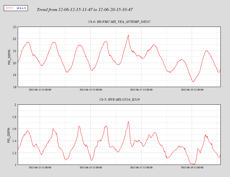
LHO Mid station gate valve annulus ion pump response to daily temperature excursions.
[Thomas, Elli, Aidan]

We re-aligned the pick-off from the ETM HR surface onto the Hartmann Wavefront Sensor (HWS). Several wedged uncoated optics were used to attenuate the beam before the sensor. We adjusted the combination of these until the beam was not quite saturating the CCD on the sensor.

We removed the Hartmann plate from the CCD and recorded the beam profile. There were diffraction rings on the edges of the intensity distribution which we assumed was caused by clipping on a couple of optics. Tweaking the alignment removed some of these effects but there is still significant clipping on the right hand side of the image that we've yet to identify the cause for [see attached PDF].

The Gaussian beam radius in the vertical direction on the HWS is roughly 1.95mm. We expect a beam size of 1.57mm. We need to adjust the magnification in the HWS telescope and confirm that we're imaging the ETM HR surface.

We replaced the Hartmann plate and ran the sensor overnight.
Rana, Keita
We also found that the view of the ETM from the optical lever viewport is very nice. It would be good if we could use that one for the ETM face cam during OAT.
Also, in lieu of having a true TransMon beam for OAT, perhaps we can setup a scatter monitor PD on an ITM chamber viewport as Bill Kells used to do: a 2" diameter lens and a high gain Thorlabs Si PD with a short pass filter.
Max F., Daniel S.

The ALS common mode board S1102638 had the following modifications applied:
R70 -> 40.2 Ohm from 1.2K
C121 -> 1 uF from 33n
This gives us a common compensation with a pole at 1.35Hz and a zero at 4kHz. The DC gain is still 40dB, but the high frequency gain is now -30dB. This allowed us to remove the Pomona box filter.

The temperature control for the laser was shorted to the shield of the controller cable. After inserting a breakout board we were able to move the laser temperature.

This in turn allowed us to engage the slow temperature integrator which made the fiber servo lock without tediously adjusting the temperature controller manually. The fast gain is now at 0dB, the common gain was set to -20dB. This gives us a unity gain frequency of about 7kHz. Increasing the gain by 3dB will excite a resonance around 270kHz.
M. Barton & S. Steplewski

On Thursday (June 14, 2012) we tried testing the L2 stage actuators. First we noticed that the binary input/output switches were not set to use Acquire/LP filters, while the switches for the corresponding ETMY L2 stage tests had been enabled. Changing the L2 stage binary IO switch to 3 enables a low pass filter that has a gain of 10 at low frequency, which sends more drive to the coils for a given excitation amount (see state machine diagram T1100507). After finding how many counts could be safely sent to the coils without saturating, we excited H2:SUS-ITMY_L2_TEST_L_EXC with one million counts of white noise to get maximum coherence in the measurement.

The attached plot shows the OSEM response with NO DAMPING at the top stage to clearly see resonances. The peaks roughly line up with the resonances we are expecting in the suspension model. The magnitude of the response is very similar for three out of four OSEMs, but the (upper right) UR OSEM is lower by nearly a factor of 5 in amplitude. The reason for this is not totally clear, but it could be that the position of the UR OSEM is different so that it doesn't apply as much force to the PUM as the other three.

The DTT session that was used to generate these results is in:

/ligo/svncommon/SusSVN/sus/trunk/QUAD/H2/ITMY/SAGL2/2012-06-14_H2SUSITMY_L2_DTT_actuation_tests_LTF.xml
ICC was completed on HAM6 today. Inspection and other close-out activities, including FTIR samples, were completed by 9 am. We did not start work in HAM5 since the forklift was not available to remove the support table so the crew was freed up to work on other activities (HAM Install Arm trial run @ HAM2, MCB work @ HAM3, logistics work at MX).
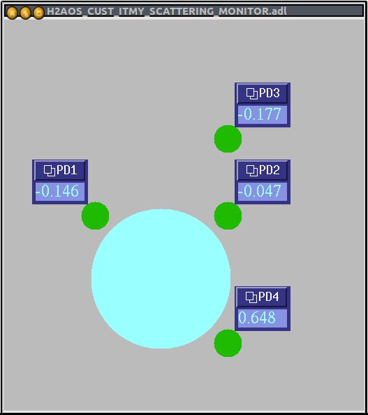
I made a simple MEDM screen for IY baffle diodes:
/opt/rtcds/userapps/release/aos/h2/medm/H2AOS_CUST_ITMY_SCATTERING_MONITOR.adl
Note to self: The screen is meant to be the view from the HR side.
The GDS software (diaggui, awggui, foton, ezca*, etc) has been updated on the suspension and seismic test stands to include modifications for the June 30 leap second. Also, the diaggui and awggui channel selection menus have changed to include 6 levels of hierarchy in the channel selection. This should make selecting channels easier as the very long menu with the tiny scroll bar has been replaced with hierarchy.
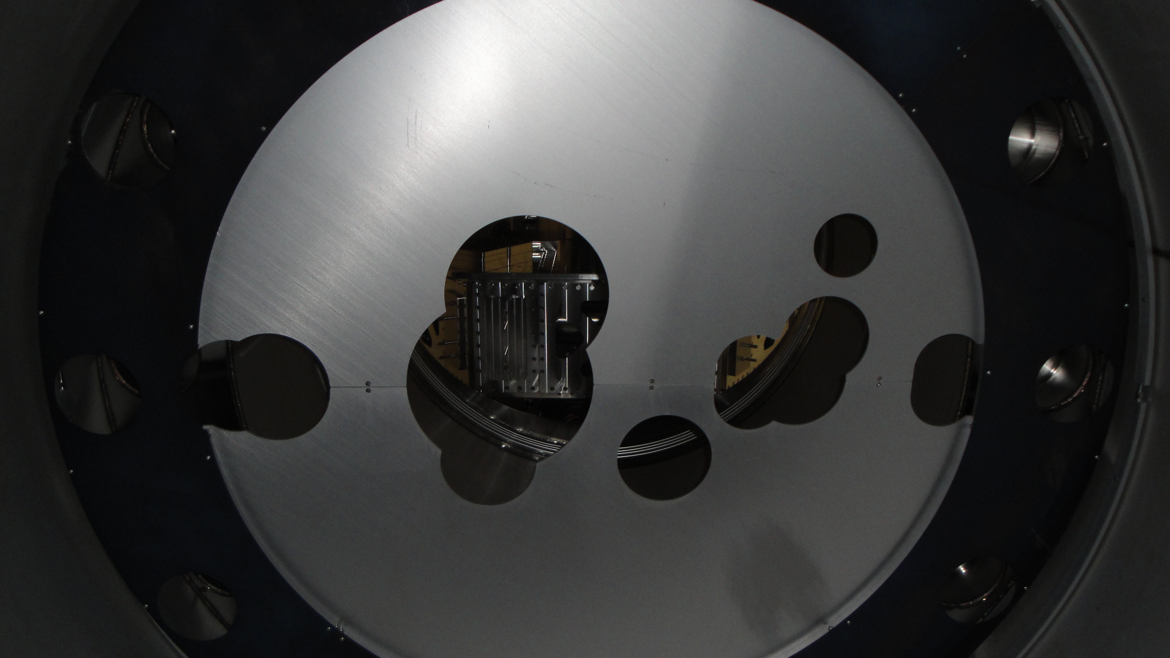
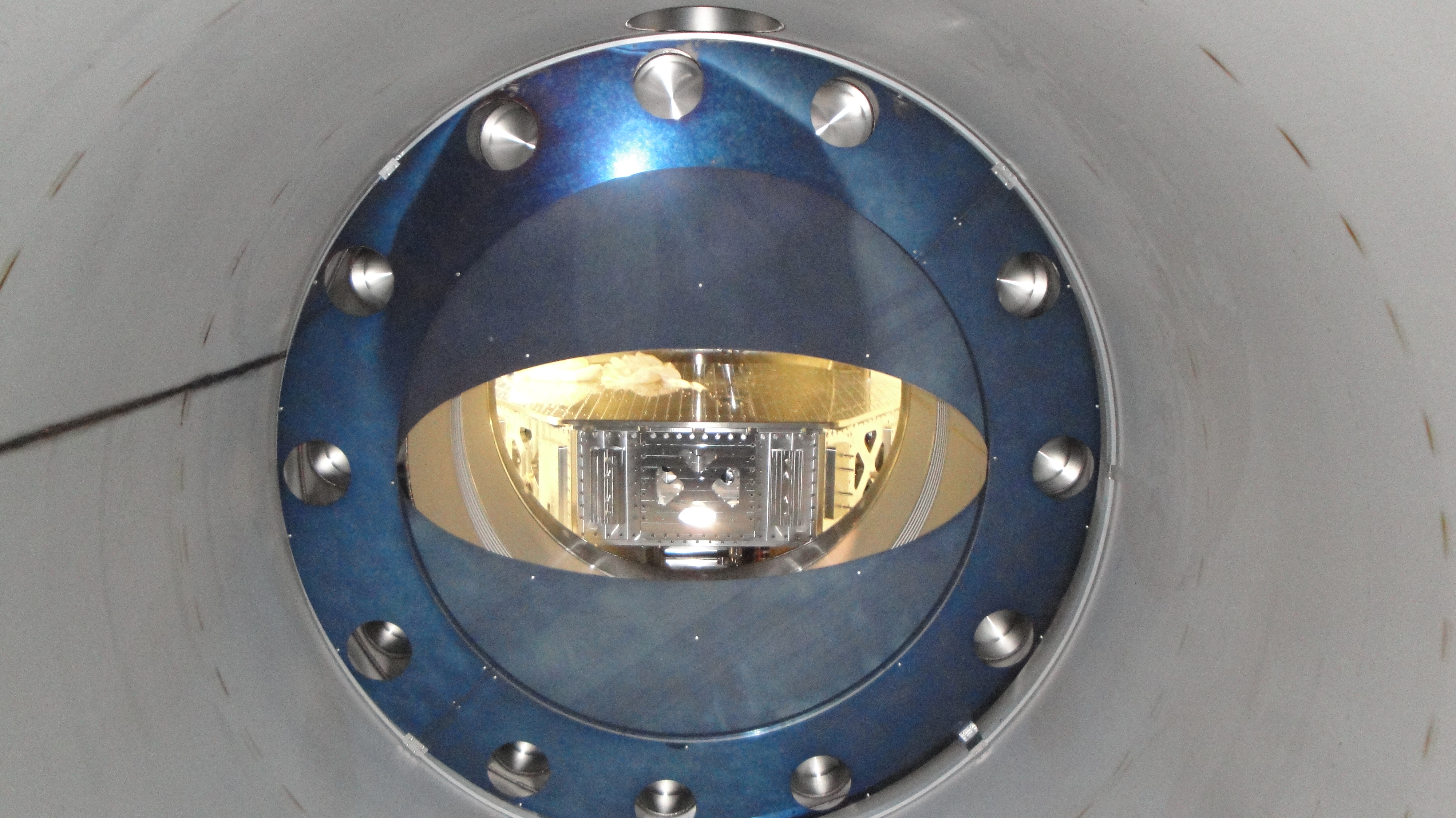
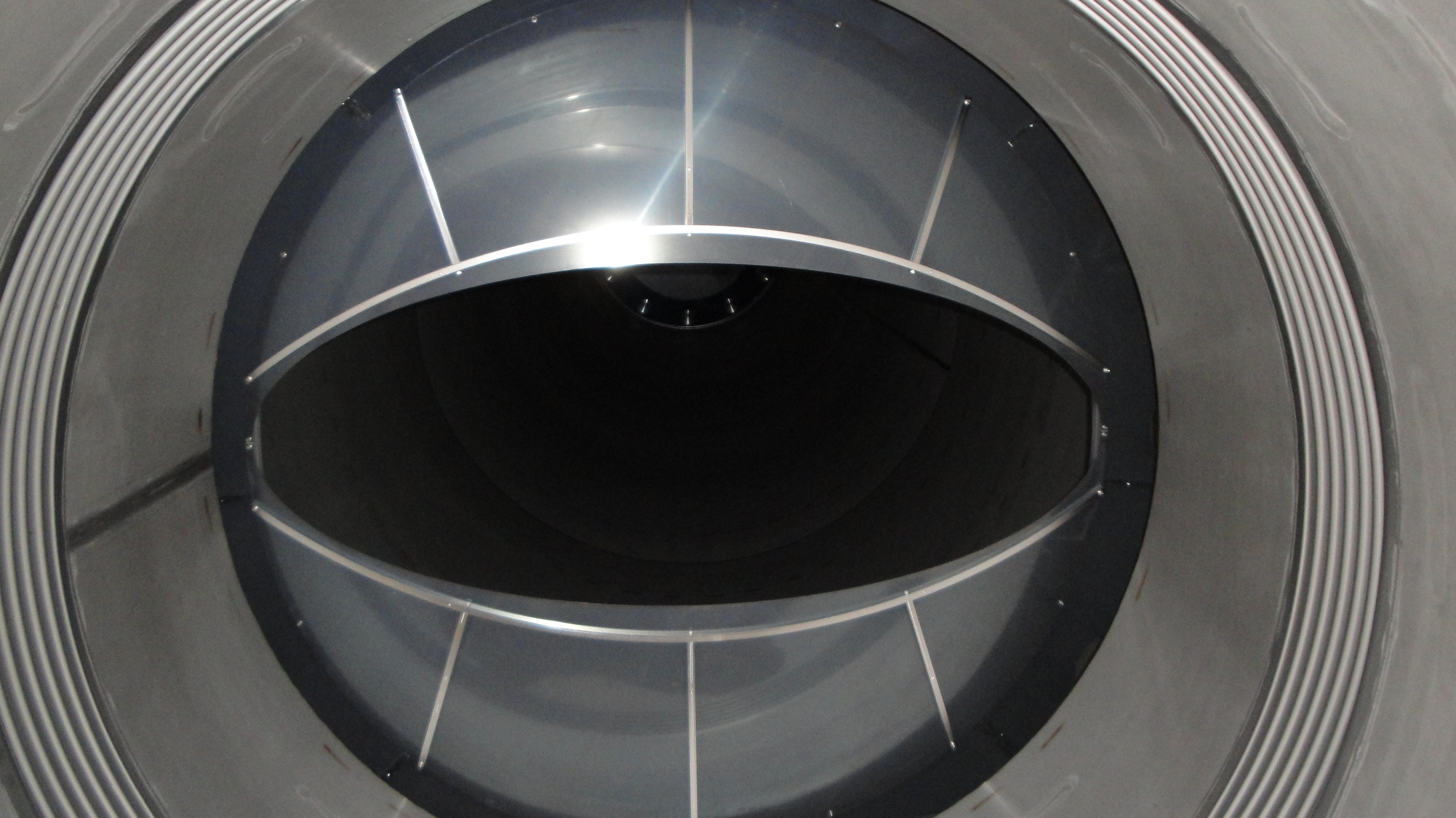
Report includes work from Friday, 15 June, since I did not alog that day.
On Friday, brushing and first vacuum in HAM6 (The chamber formerly known as HAM5)were completed. Today, the crew worked on wipe down which took most of the day (that is much longer than it usually takes to wipe down a HAM). The chamber did not look much better after wipe down than it did when cleaning started so Bubba and I asked John to come out and have a look. The crew took some pix  including a close-up that shows an "orange peel" surface that appears to retain quite a lot of the original oxide(See below). Second vacuum was completed just prior to end of shift. John asked me to let Rai and Mike Z. know what we have found so that they can weigh in.
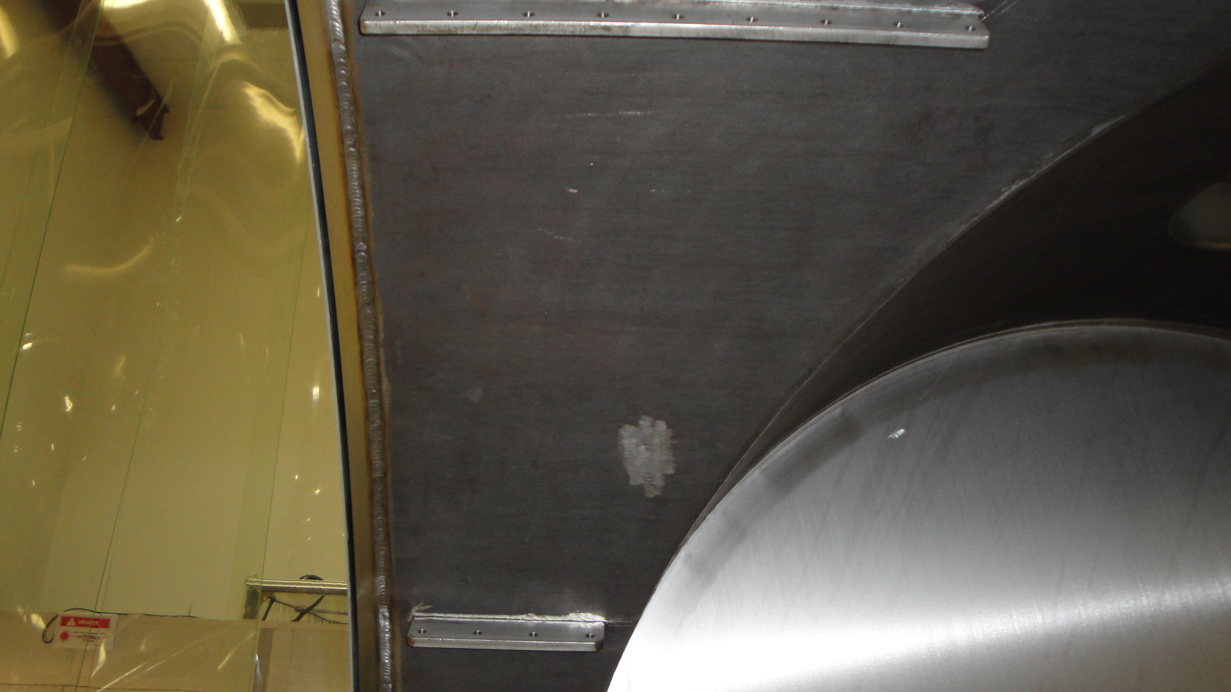
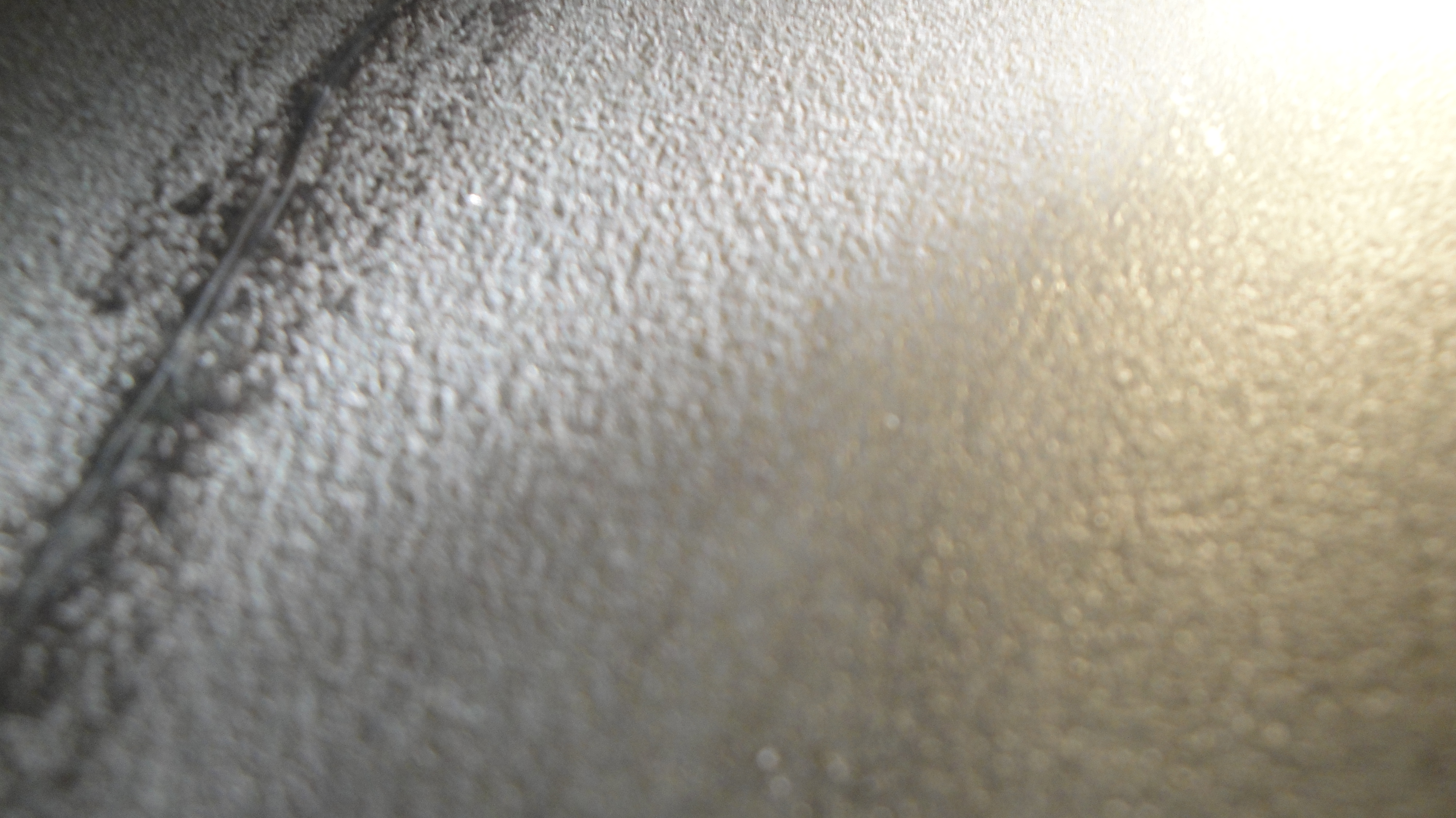
Below is Rai's response to the reported condition of HAM6 interior.
"I don't know what to make of these surfaces. It looks as though they were heated by welding and then quenched while still fluid. I don't think you can do anything about the surface but I also suspect they are not a major particle source."
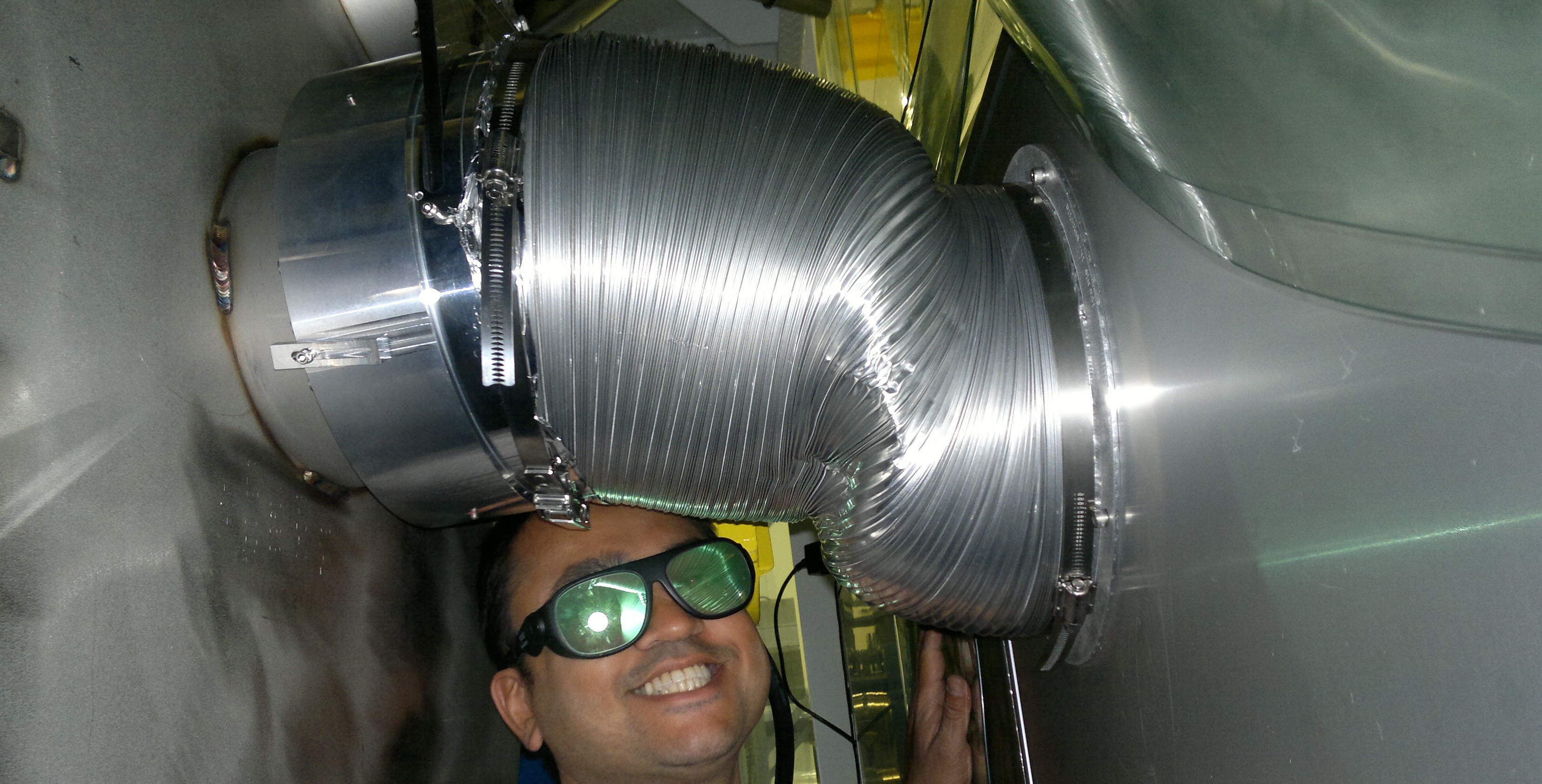
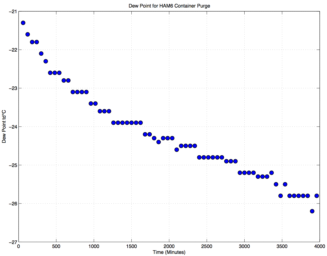
HAM6 was placed into a shipping container around January 27th, Corey's alog, and purged with a Nitrogen boil-off from a dewar. To the best of my knowledge it has not been purged since that time. To determine what the humidity levels inside the container were like, a super elaborate no expenses spared contraption was developed to capture the exhaust from the container during the purge (photos attached). Data logging using a testo 645 dew point probe was started as soon as the purge began and ran for about 19 hours (graph attached).

Direct LN2 boil-off read at -48.5 td°C, 9.2 °C; while ambient LVEA readings were at 4.4 td°C, 20.1 °C. Purge rate is ~10 L/m with ~5,442 L of empty volume inside the container.
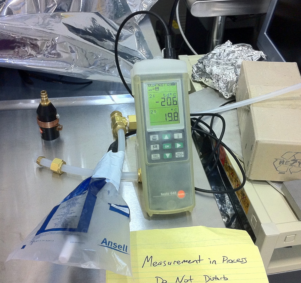

Future data from purges will be stored on the DCC here. T1000714.
Over the weekend (6-15 to 6-18) purge of the HAM6 shipping container.
Attached is a handy Moisture Conversion Table by request of John Worden.
