This was the first attempt after the viewport was rotated back, and our alignment was still at the same bad position and the beam was not hitting the ETM. So apparently something moved, but we couldn't figure out what.
Anyway, we steered the beam back by adjusting the ALS table periscope mirrors, using the green QPDs on the TMS ISC table. then steering the TMS itself so the beam retro reflects back to the ALS table through an aperture we set up on the ALS table. We didn't use the picomotors as we knew that the alignment was pretty good two weeks ago and we were sure that that the picomotors were not moved since then.
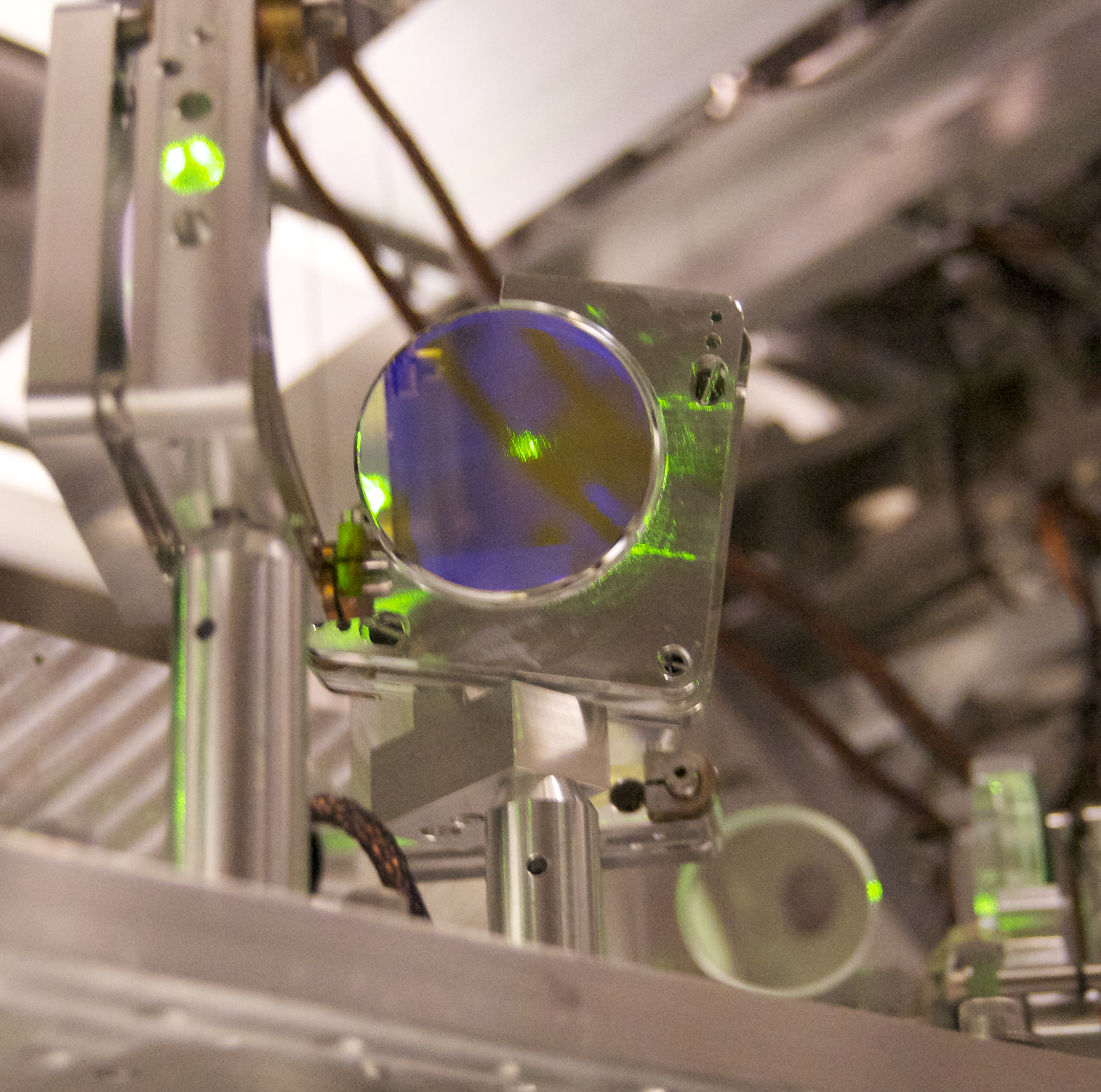
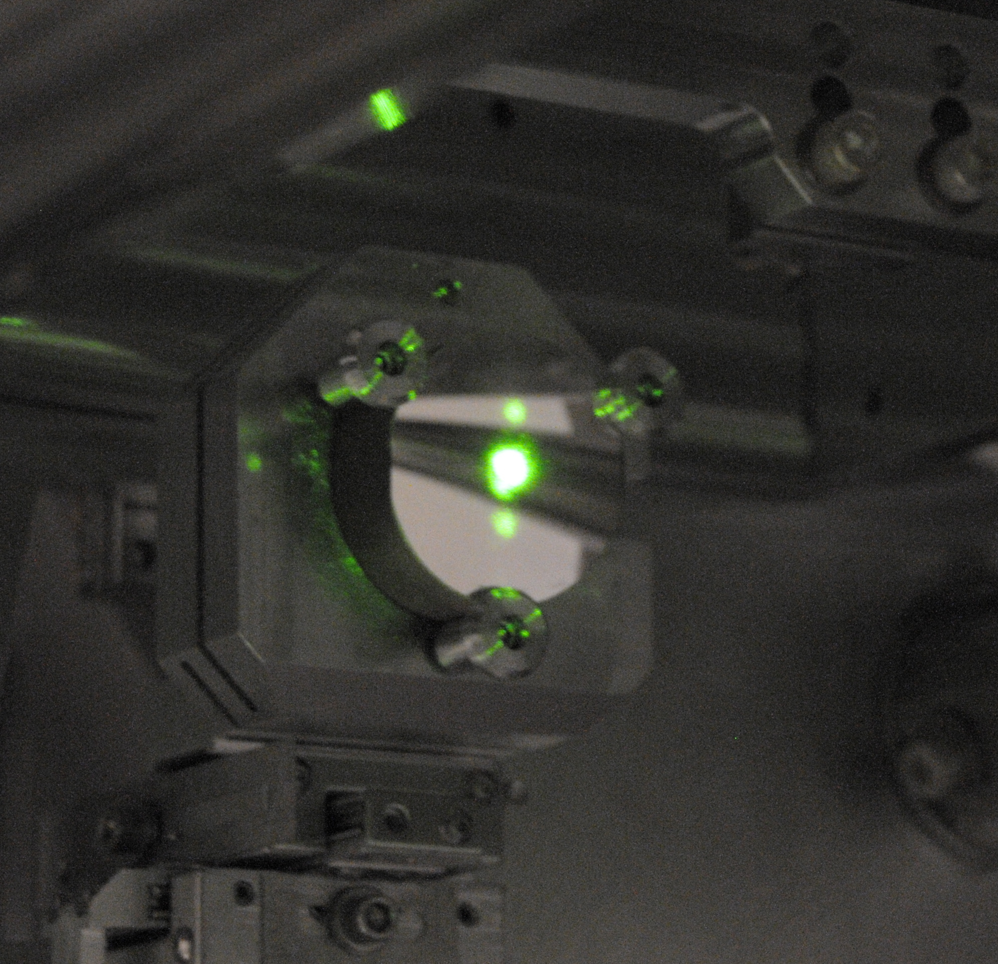
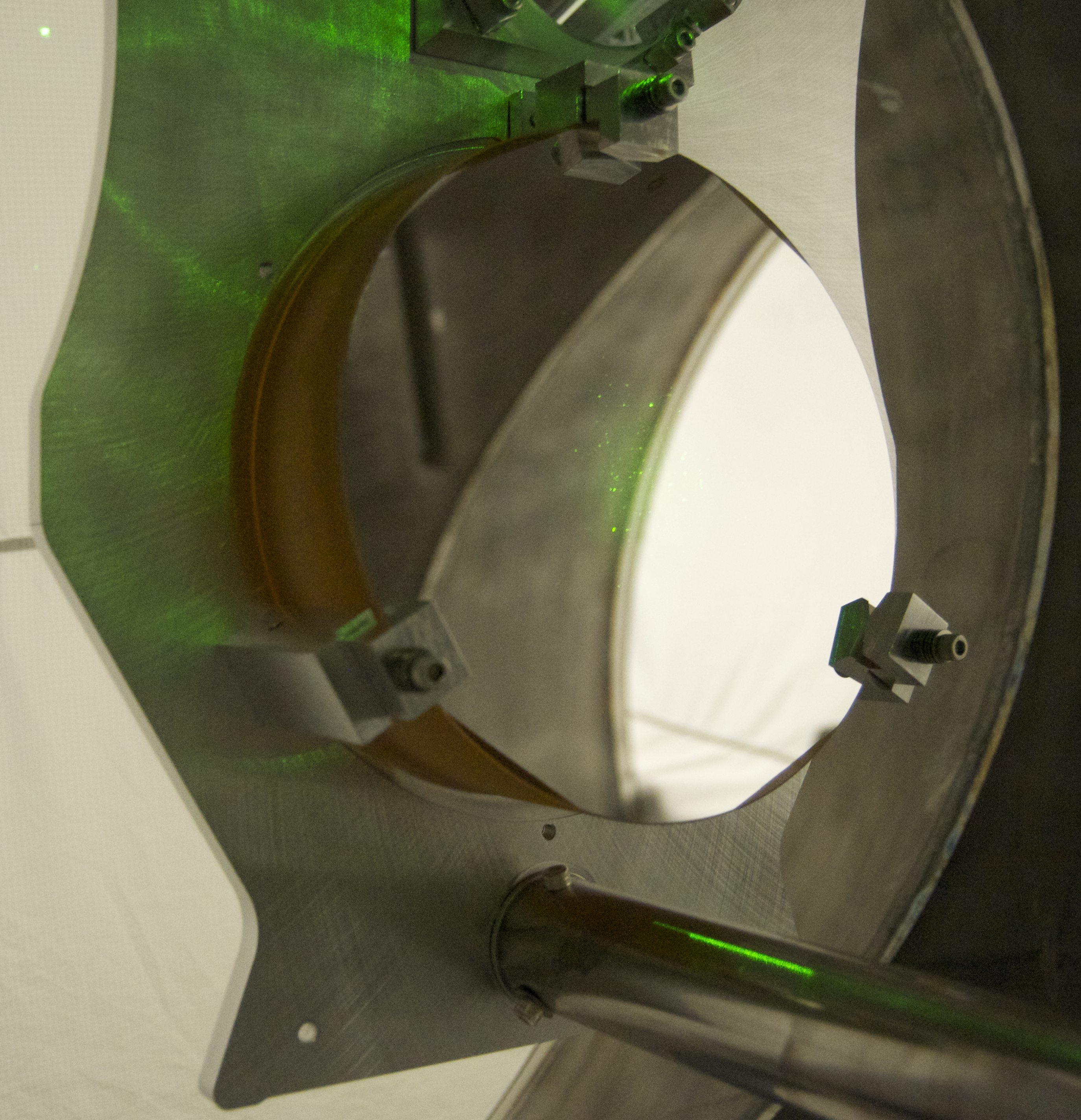
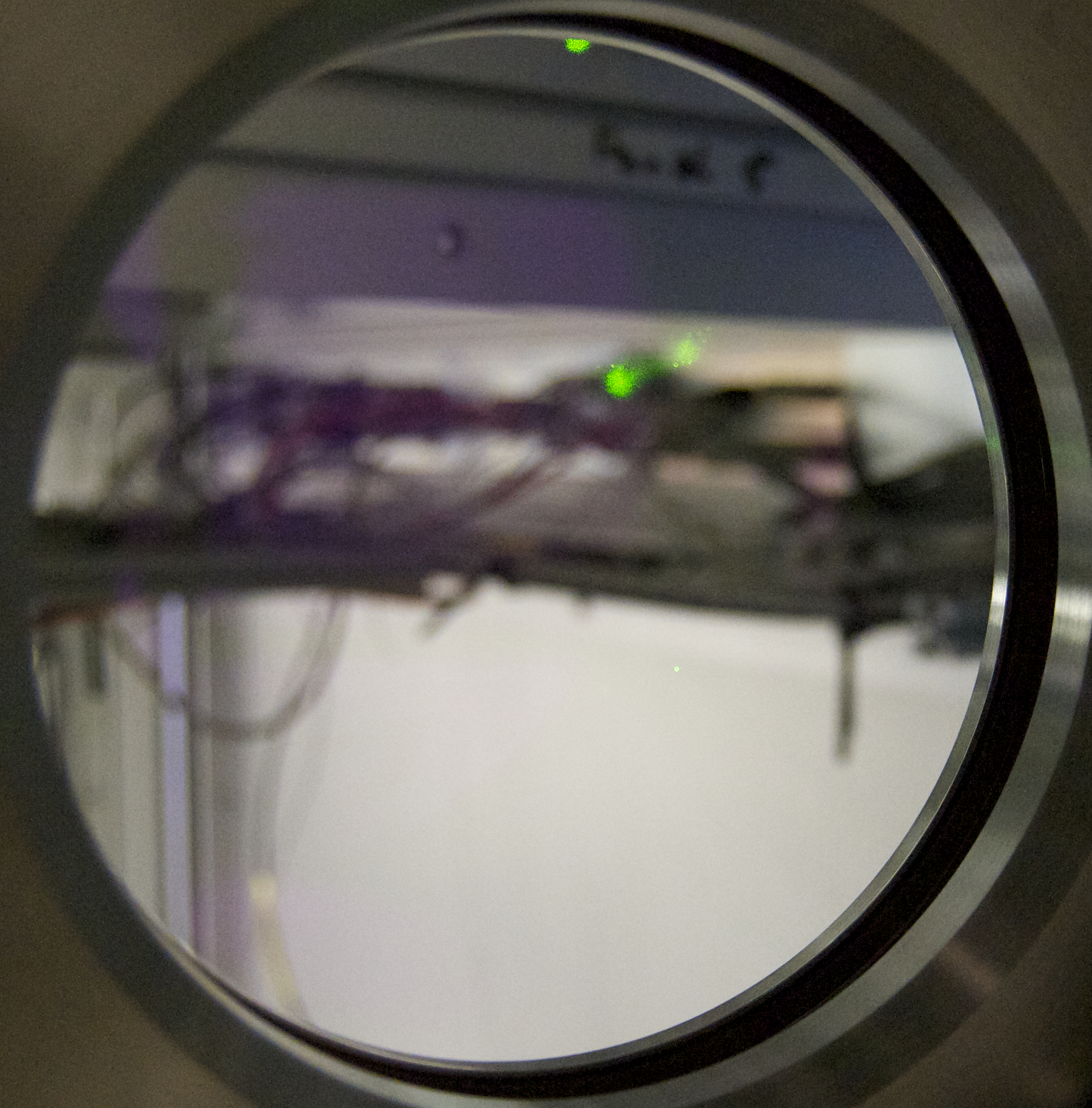
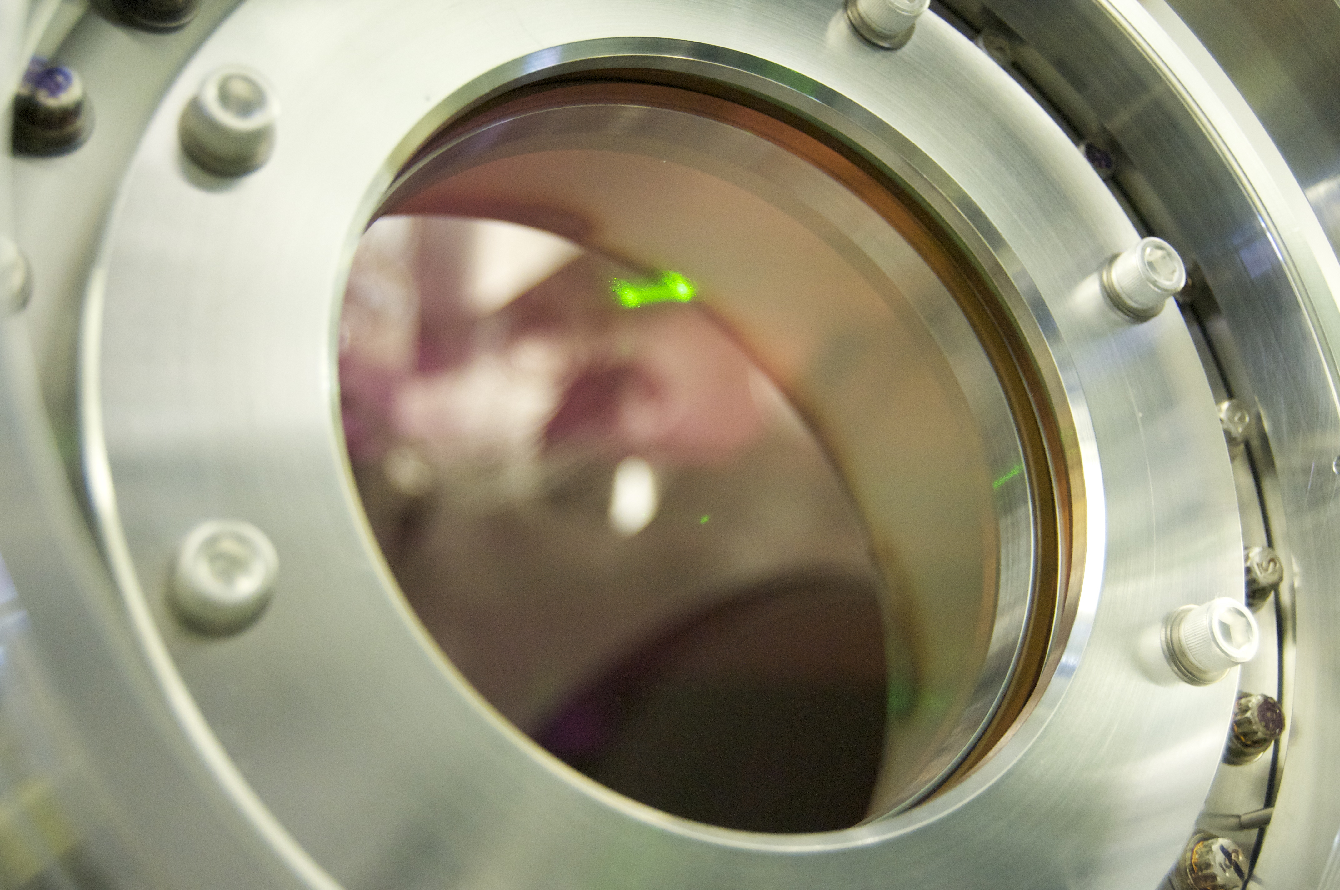
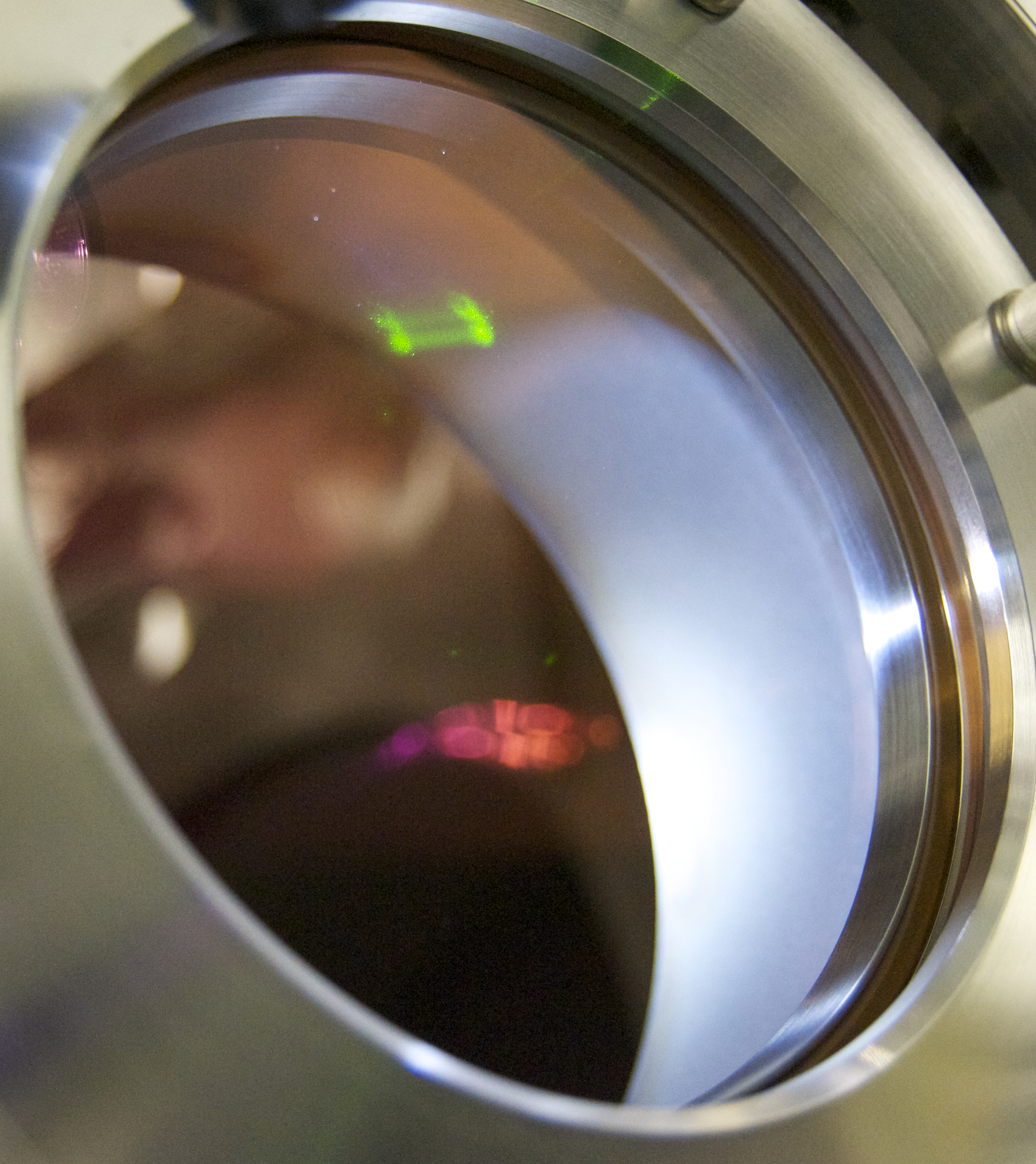
After some tweaking, the beam looked really good at the secondary, F2, and the primary (Cheryl took pictures). It was low on F1 (a bigger of the two folding mirrors on the TMS telescope), but in the end I think it's more important to have the secondary and the primary reasonably well centered than the folding mirrors, and the beam retro reflects, so I think we're in a good shape.
The new offsets: 16000 counts for PIT, -5100 counts for YAW.
Before we started, Cheryl noticed that the EQ restraint bar is not centered any more (it used to be reasonably centered). We readjusted the bar position.
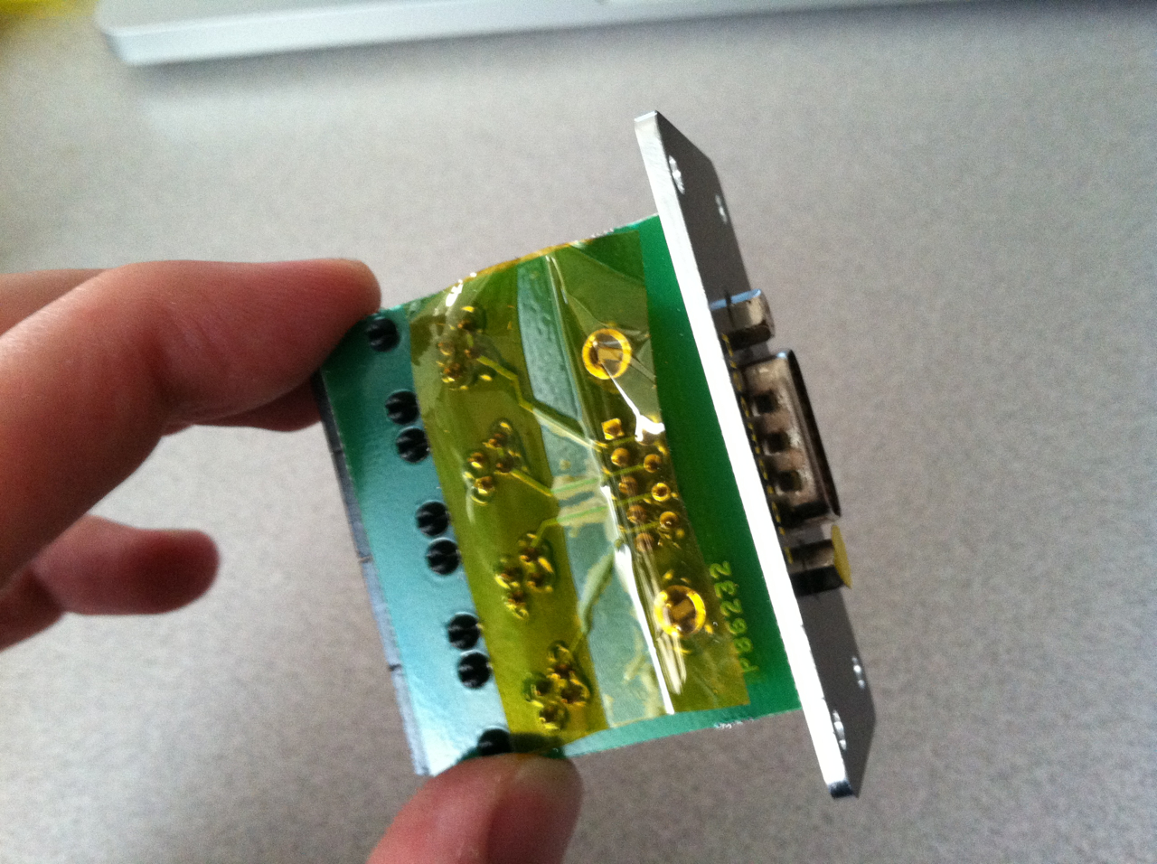
We also relieved that crazy PZT offset. It was on YAW of the upstream PZT mirror. Since the PZT mirrors themselves don't have any fine manual adjustment, we used the closest steering mirror. The input to the MCL PZT controllers were terminated. This made a tiny change in the alignment (which we were able to measure by QPDs) but these were taken care of manually by the periscope mirrors later.
The diff-single converter on the field rack as well as the anti-imaging chassis on the ISC rack was turned off.