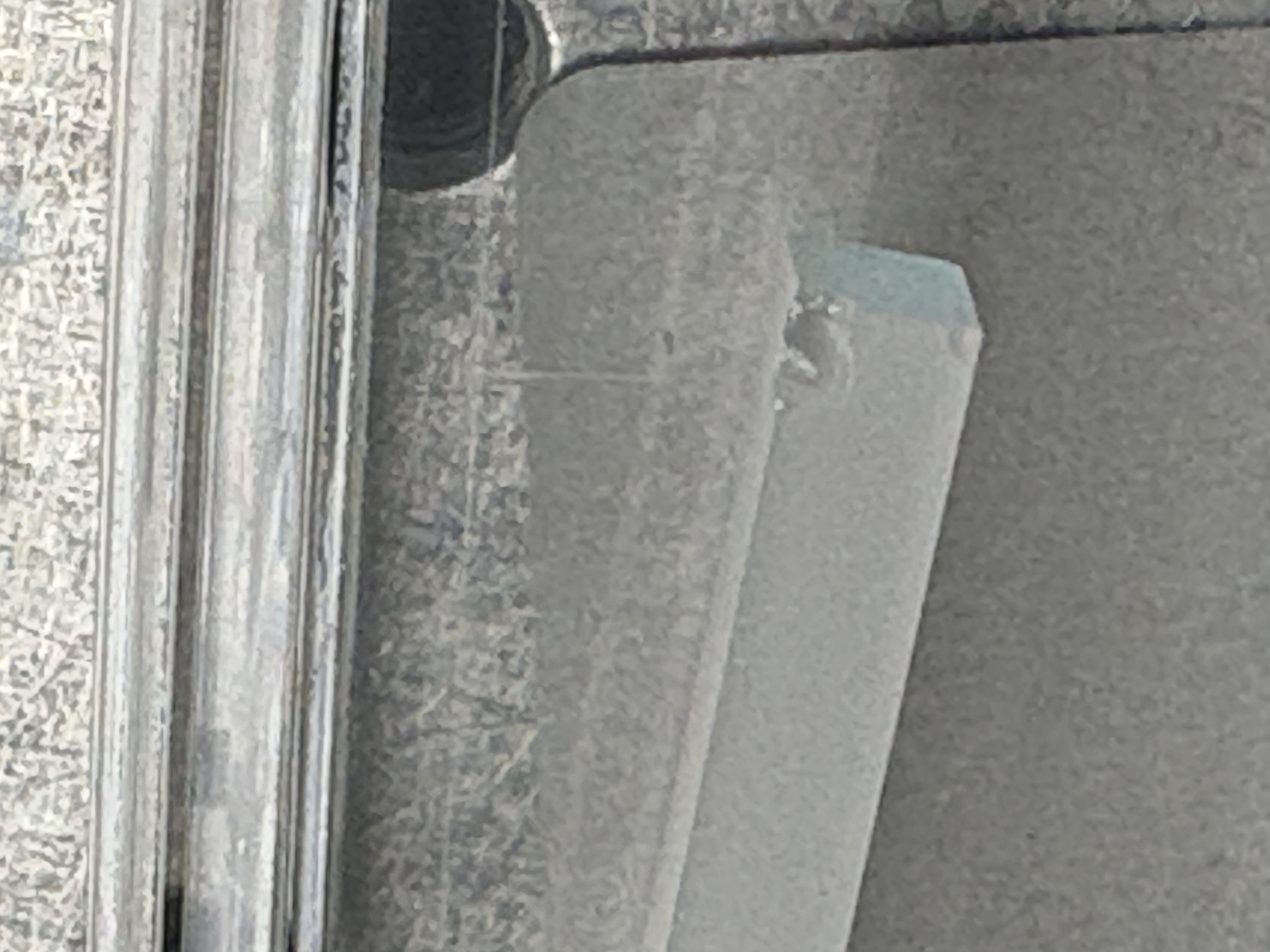
Following alog 89115, we found that the old batch crystal from that alog (S/N10252003) had a big chip at one corner. It is pretty bad we don't want to use that.
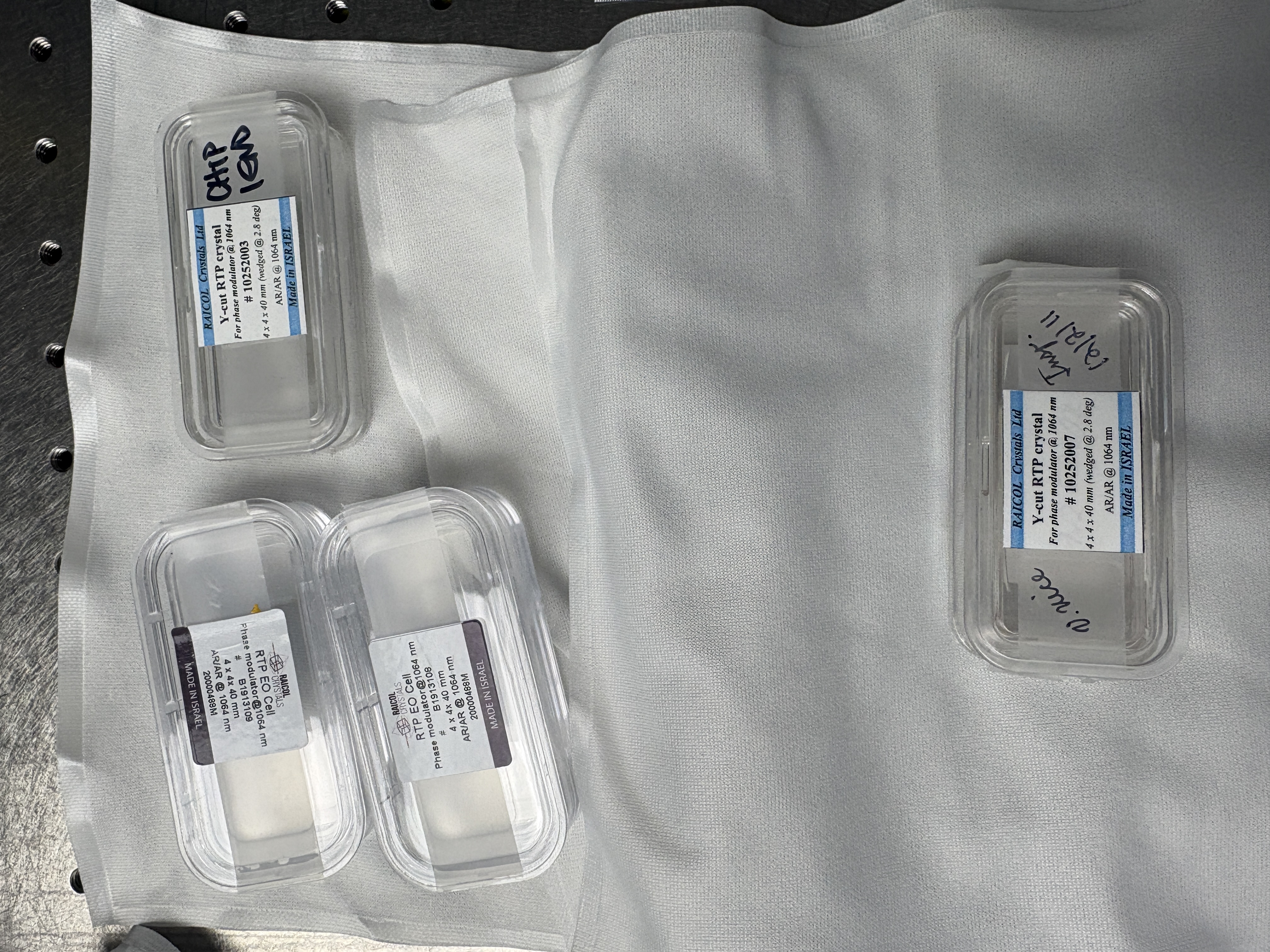
Betsy found another old batch (S/N10252007, "inspected 12/21/11" and UF tag dated 4/21/09), so we A-B-ed that one with the spare new batch (S/N B1913108).
The beam path was made as level as possible at 3" height using a beam leveling tool (a black metal thing with a tiny aperture at each inch of height).
We put the crystal on a platform that is roughly 2" 29/32 (which is about 2.4mm lower than 3"). The crystal is 4x4x40mm so that's about the right height.
We spent some time to make YAW alignment as good as we can for each of the crystals.
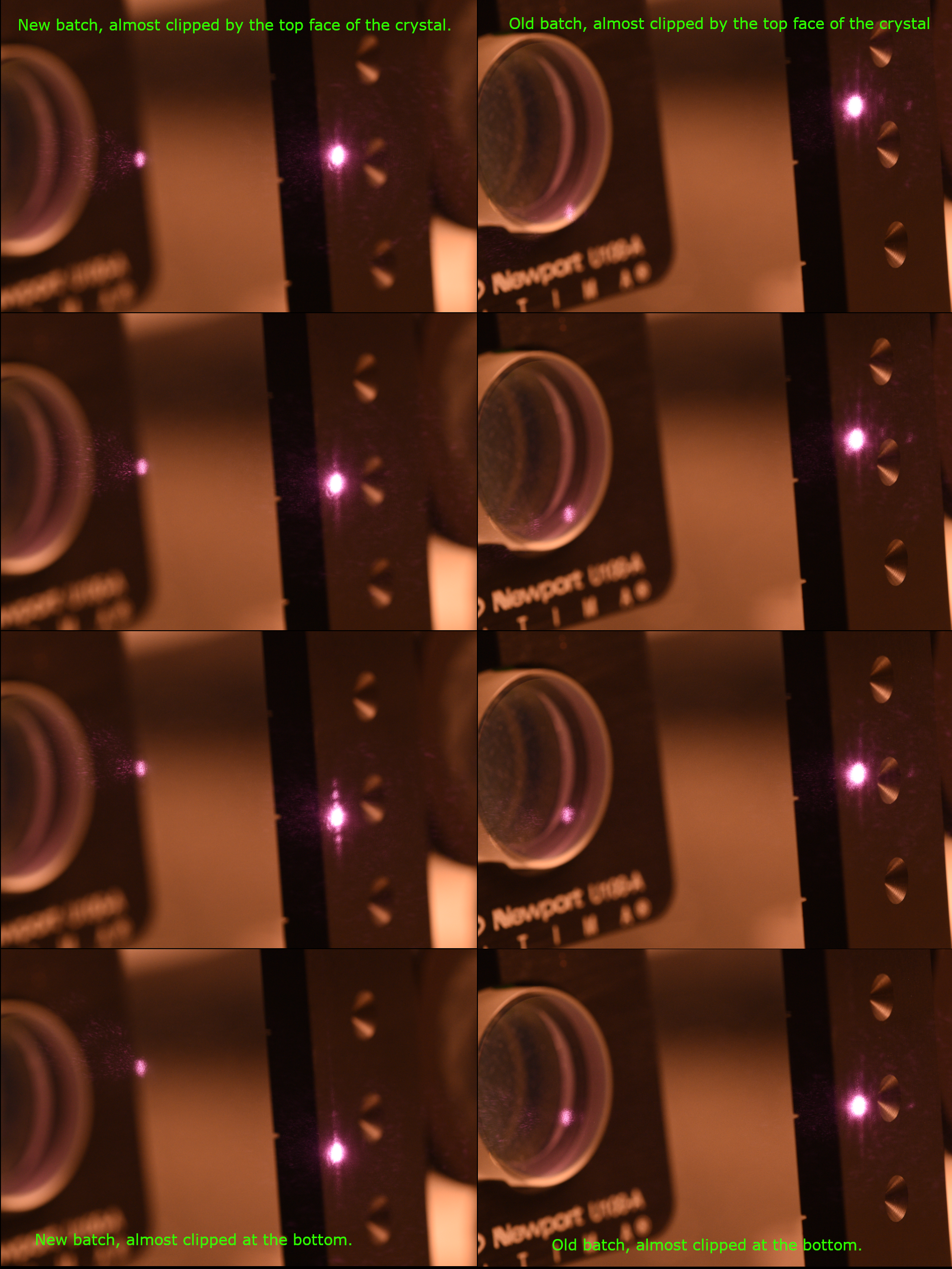
We scanned the beam in PIT from top to bottom (or bottom to top), each extreme is where the beam is almost clipped (but not actually clipped) by the top or the bottom face of the crystal.
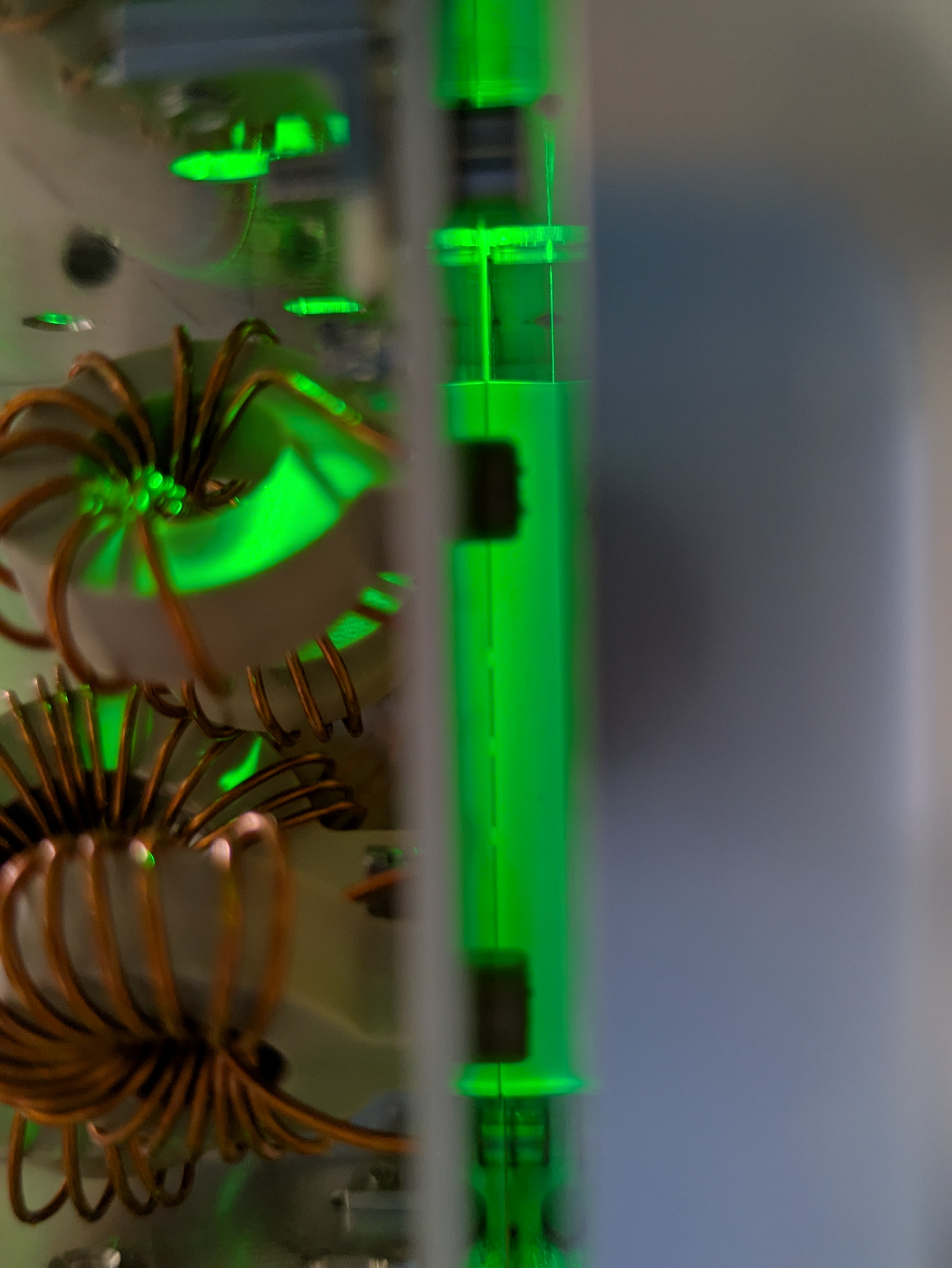
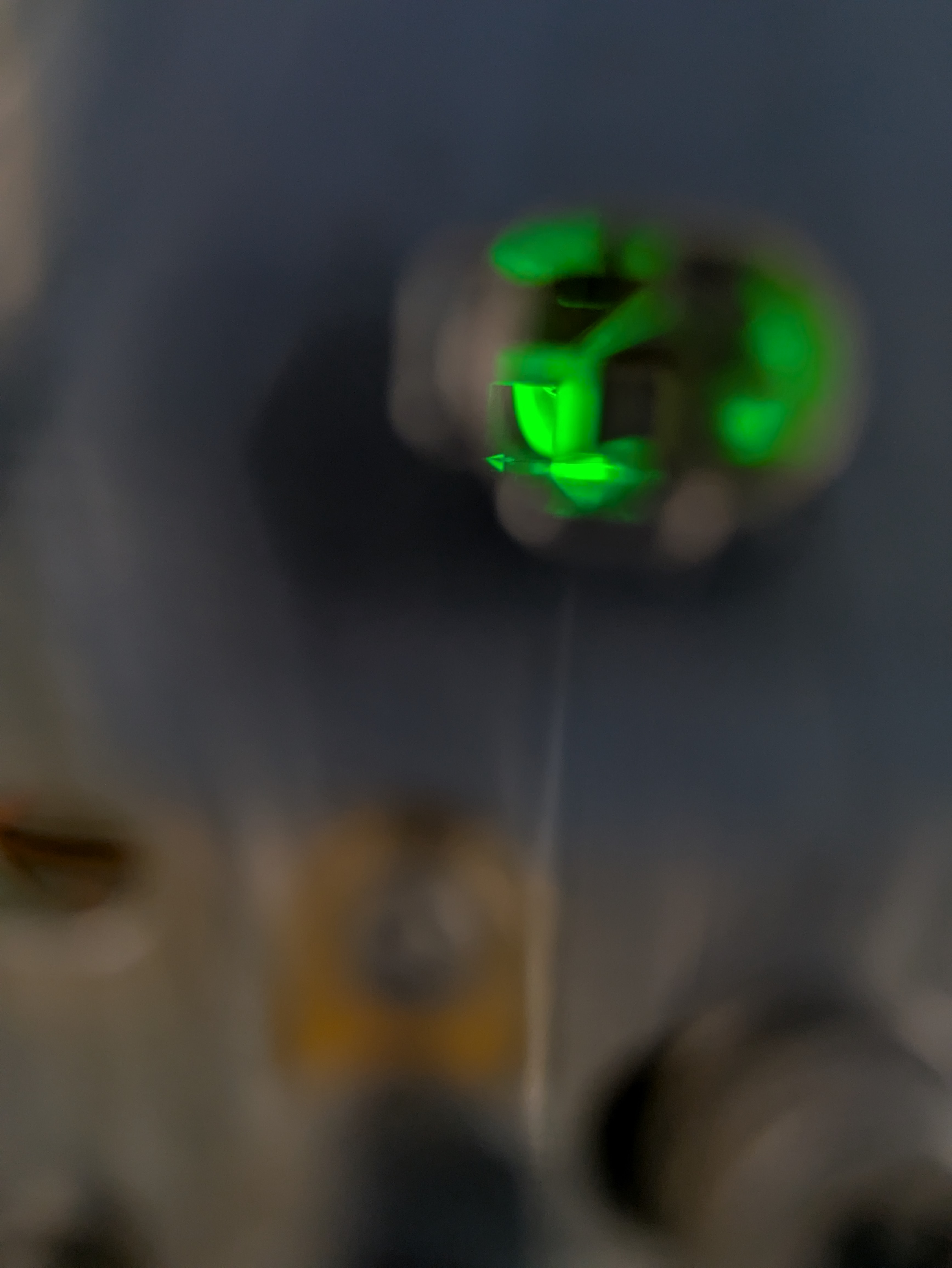
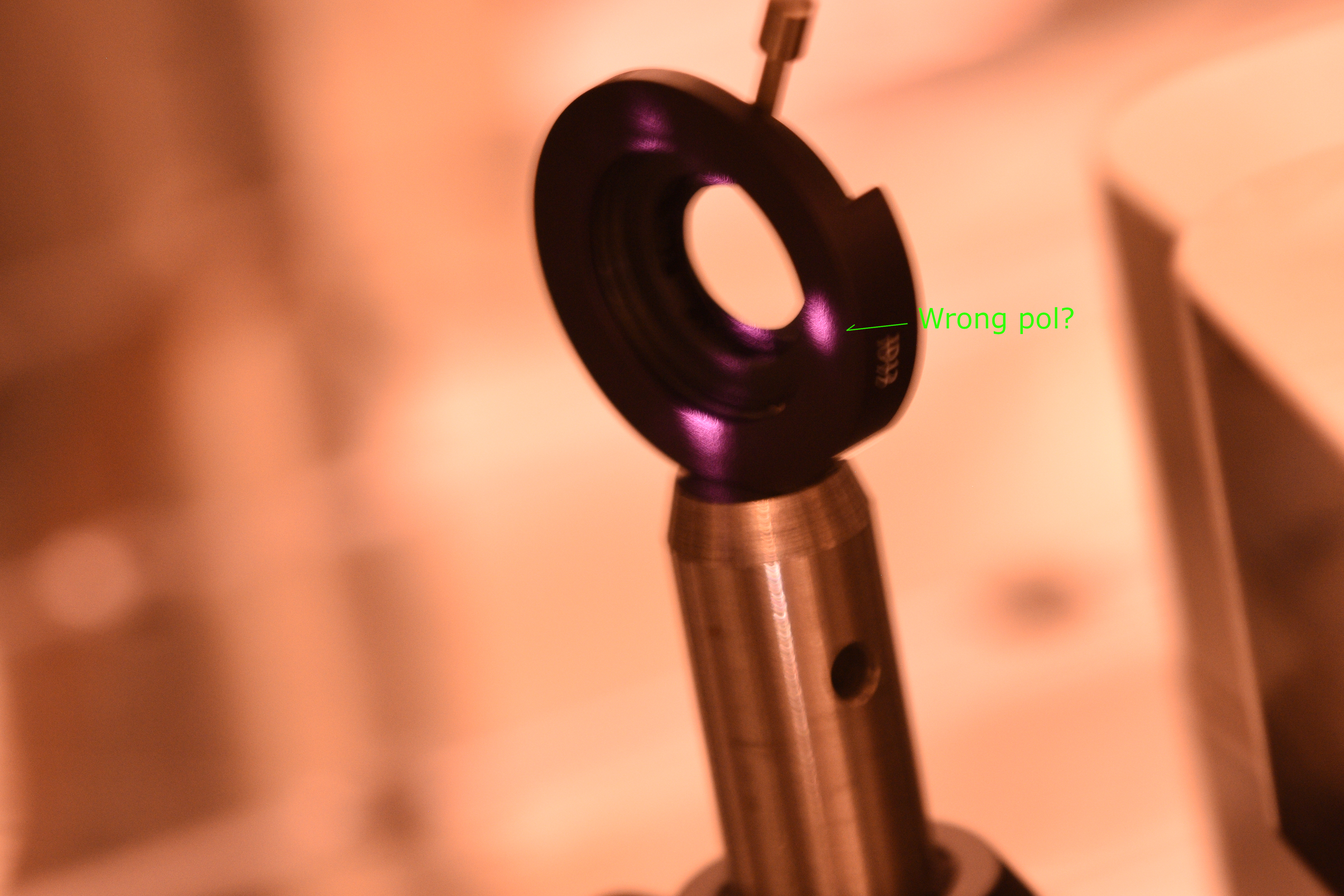
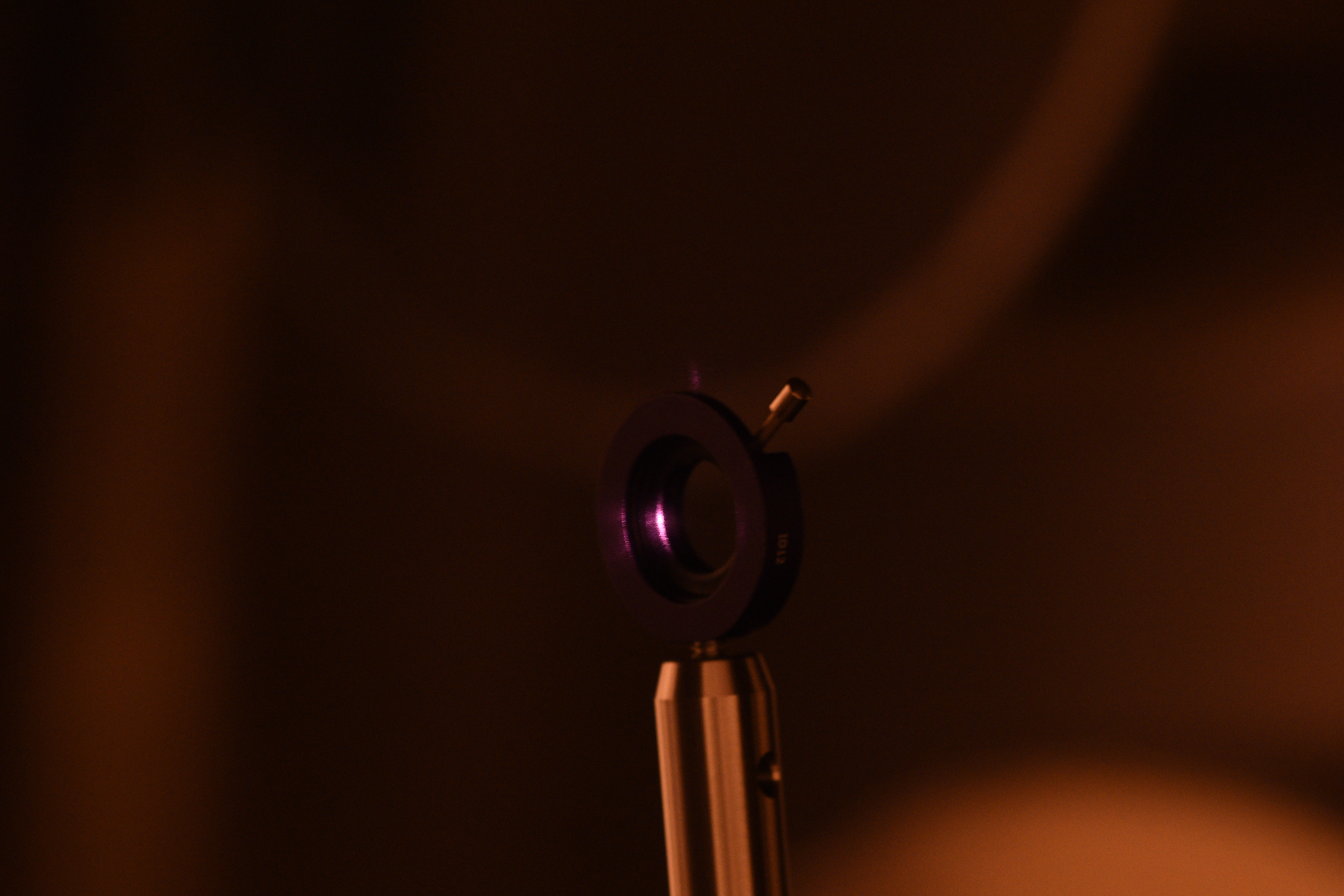
Look at the attached, the new batch (left column) clearly shows multiple beams even though the focus is not as sharp as the old batch photos. As we misalign in PIT, the dark place moves relative to the main beam and the contrast changes too, but multiple ghost never went away. At the extrema (very close to the top or bottom edge) it looked as if the beam is better but I'm not sure it actually was.
The old batch (right) didn't show such a behavior. The beam shows something like a diffraction pattern but no separate ghost beams. Everything moved with the main beam. Not sure if the diffraction pattern came from the aluminum surface or EOM, but clearly this is MUCH better than the new batch.
Note, due to the apparatus (the steering mirror is 20" upstream of the EOM), we haven't searched in a huge PIT angle space, it's actually roughly +-4mrad or so, the angle is not negligible but it's more parallel displacement scan than an angle scan.
Also note, when the crystal was put in place it seems that there's some vertical deflection which was different for the old and the new. On the top two pictures, there's no change in the input alignment into the crystal.
Based on this observation, I'd say using the old batch makes sense. LHO people (Jennie, Rahul, Betsy and myself) had a brief conversation with Masayuki and MichaelL and we all agreed that that's the way to go.


