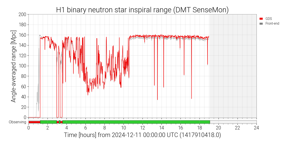
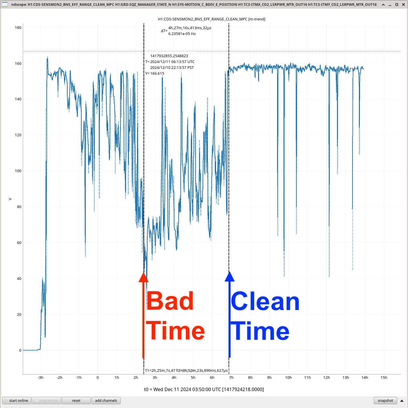
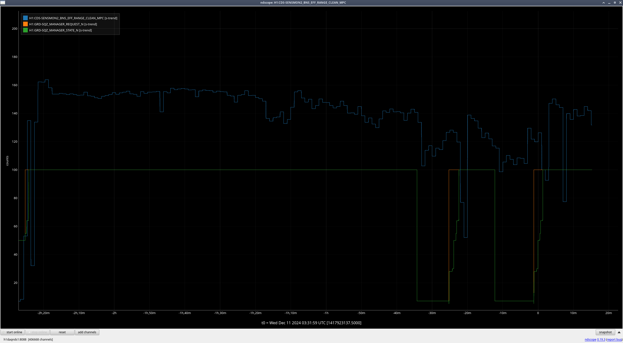
The broadband glitching that was present in the early hours of Dec 11 (UTC) appears to have suddenly and entirely stopped at 10:36:30 UTC - this sharp feature can be seen in the daily range plot. I completed a series of LASSO investigations around this time in the hopes that such a sharp feature would make it easier for LASSO to identify correlations. I find a number of trend channels that have drastic changes at the same time as this turn-off point related to TCS-ITMY_CO2, ALS-Y_WFS, and SUS-MC3_M1.
The runs I completed are linked here:
- LASSO run of the first half of Dec 11 with the sensemon range as the primary channel
- LASSO run of times near the turn-off point with TCS-ITMY_CO2 as the primary channel
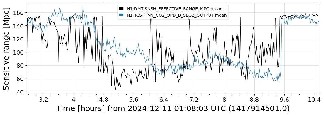
- LASSO run of times near the turn-off point with the sensemon range as the primary channel
Run #1 was a generic run of LASSO in the hopes of identifying a correlation. While no channel was highlighted as strongly correlated to the entire time period, this run does identify H1:TCS-ITMY_CO2_QPD_B_SEG2_OUTPUT (rank 11) and H1:TCS-ITMY_CO2_QPD_B_SEG2_INMON (rank 15) as having a drastic feature at the turn-off point (example figure). Based on this information, I launched targeted runs #2 and #3.
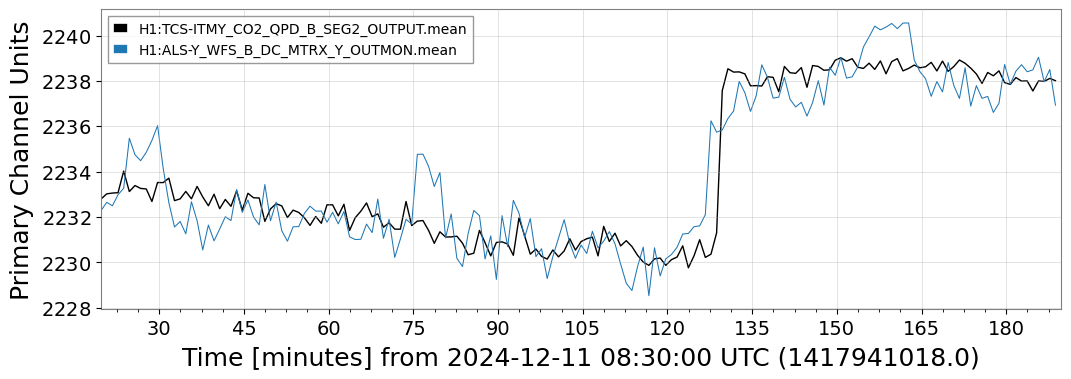
Run #2 is a run of LASSO using H1:TCS-ITMY_CO2_QPD_B_SEG2_OUTPUT as the primary channel to correlate against. This was designed to identify any additional channels that may show a drastic change in behavior at the same time. Channels of interest from this run include H1:ALS-Y_WFS_B_DC_SEG3_OUT16 (example figure) and H1:ALS-Y_WFS_B_DC_MTRX_Y_OUTMON (example figure). SEISMON channels were also found to be correlated, but this is likely a coincidence.
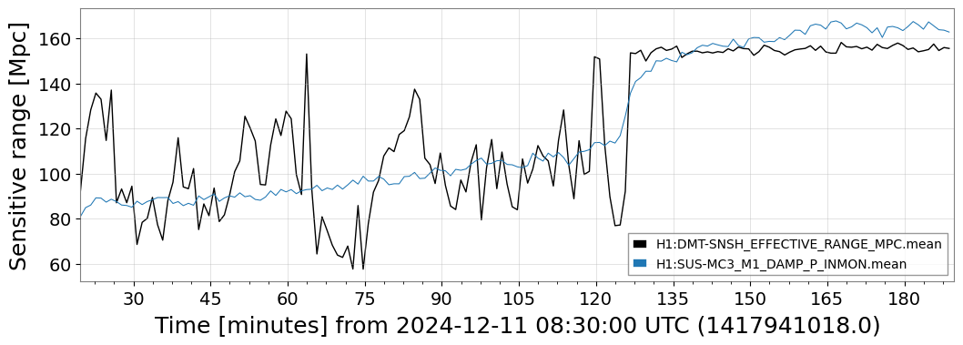
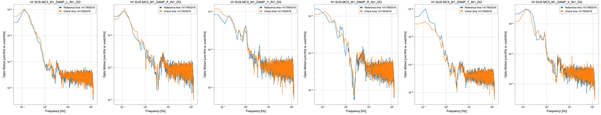
Run #3 targets the same turn-on point, but with the standard sensemon range as the primary channel. This run revealed an additional channel with a change in behavior at the time of interest, H1:SUS-MC3_M1_DAMP_P_INMON (example figure).
Based on these runs, the TCS-IMTY_CO2 and ALS-Y_WFS channels are the best leads for additional investigations into the source of this glitching.


