betsy.weaver@LIGO.ORG - posted 22:05, Sunday 30 October 2011 (1641)
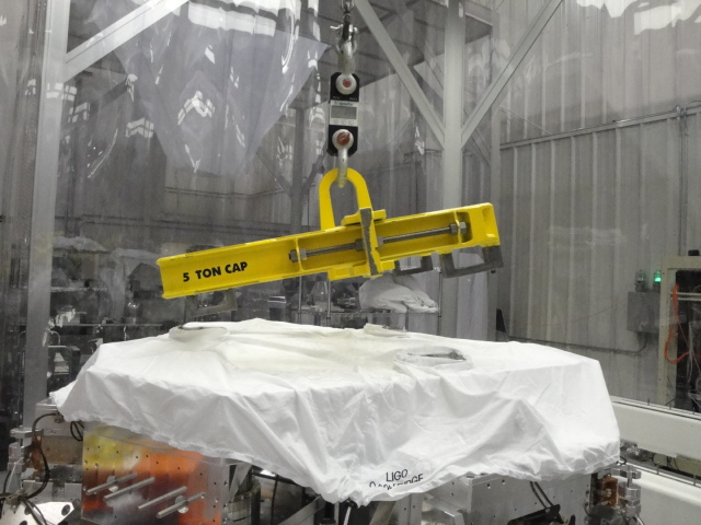
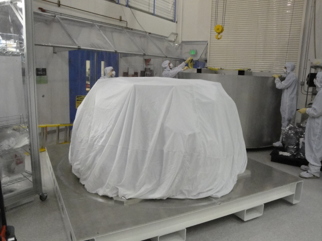
ITMy-AR First Contact reapplied
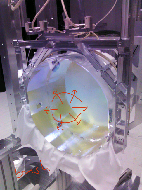
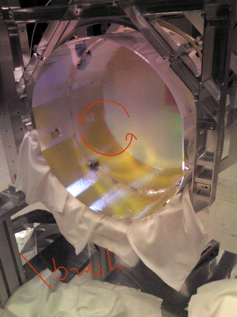
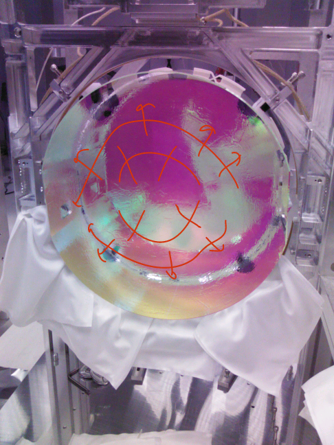
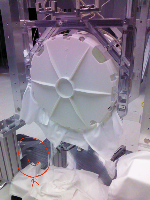
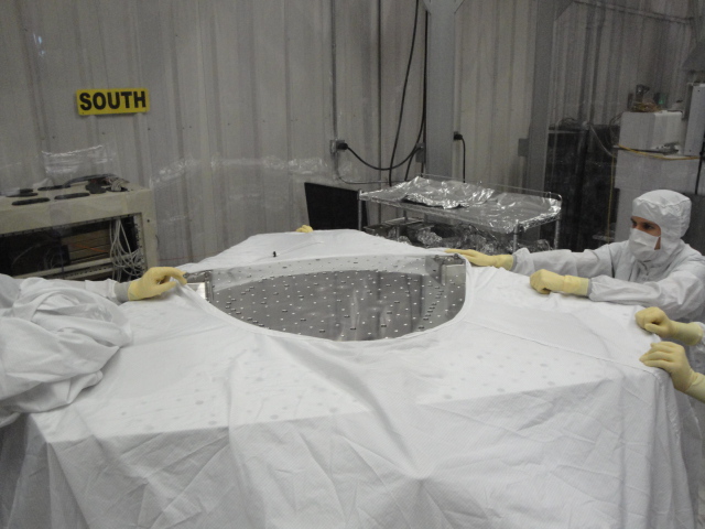
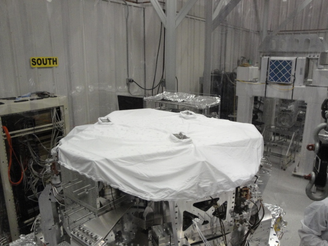
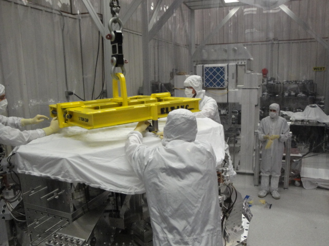
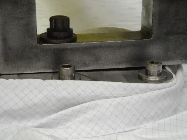
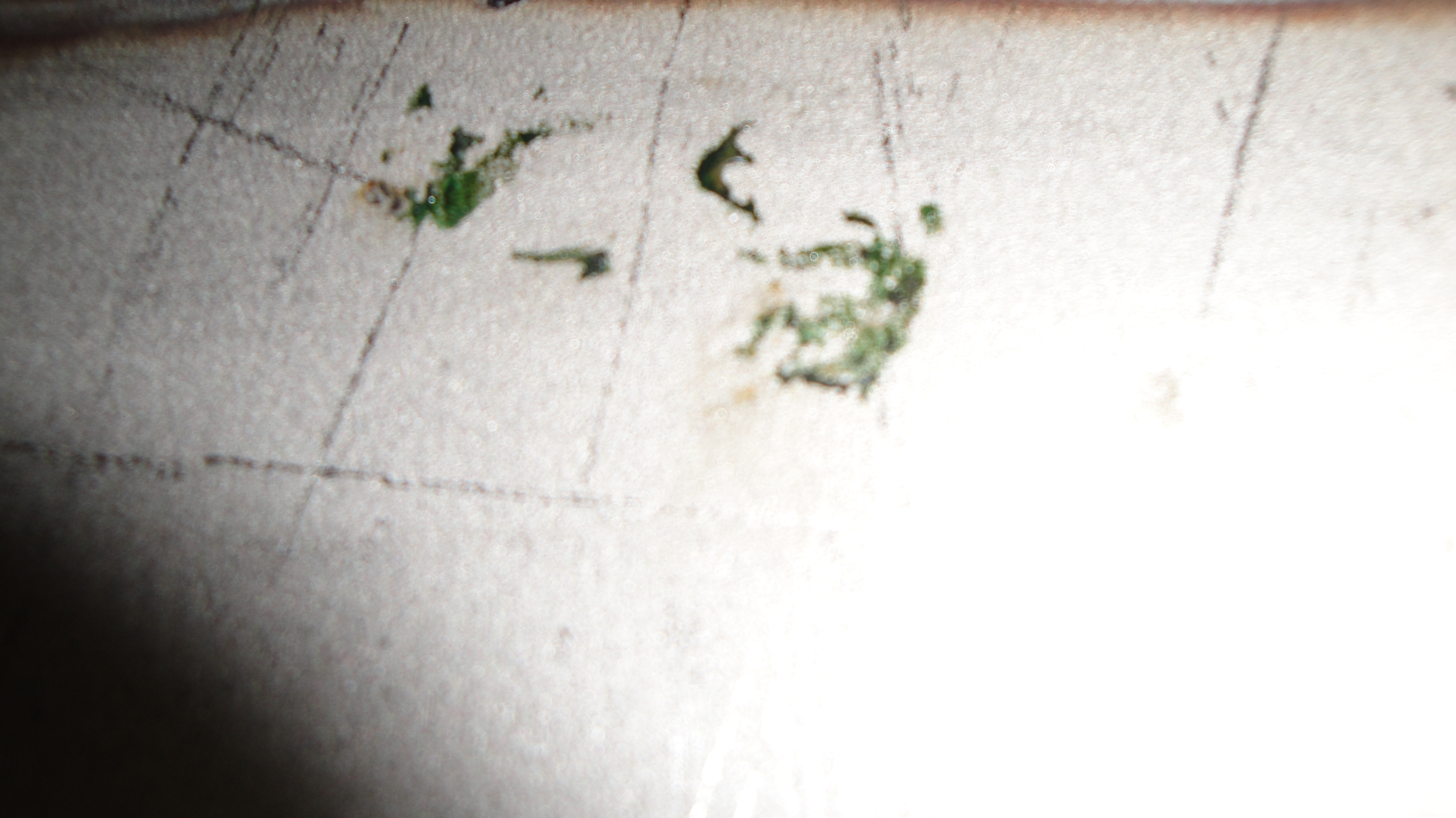
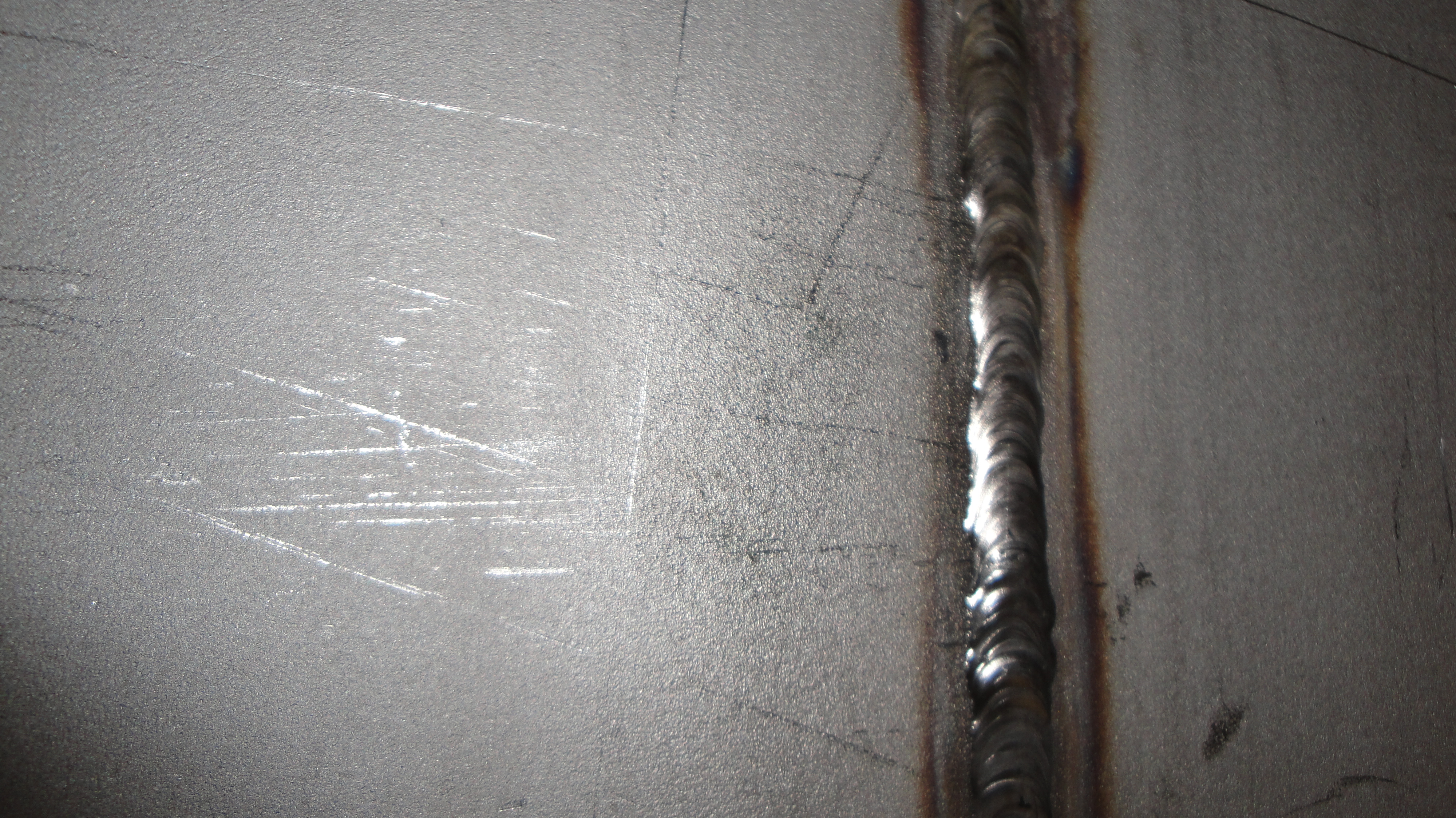
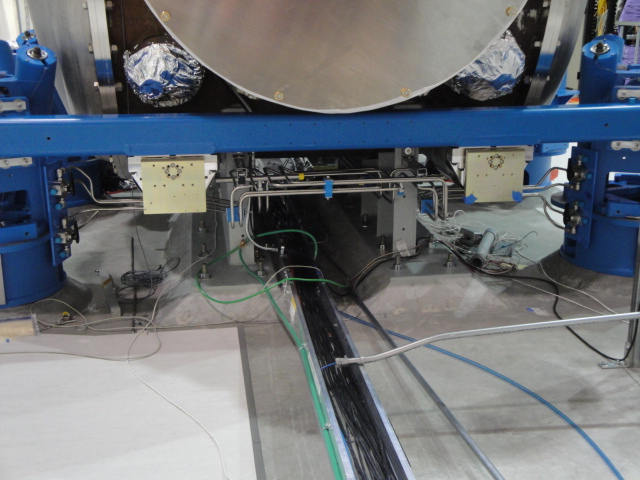
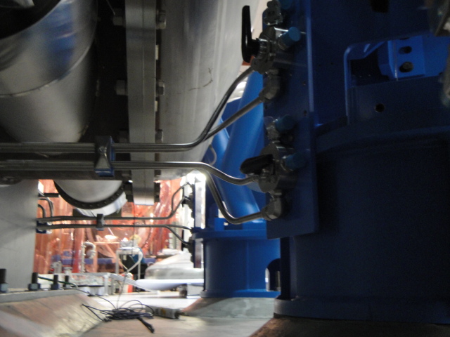
Last week, we performed cleanup of the debris from the fiber breakage on the ITMy main chain.  This was the order of the cleaning steps over a course of a few days:
Optics caps we on both HR and AR during steps unless stated otherwise.
1) Vacuumed the structure.
2) Blew the glass PUM and more of the structure top down with N2 deionizing (DI) gun.
This only removed roughly half of the particulate from the glass PUM.
3) Blew the ITMy barrel with DI gun in direction of AR to HR (cap and FC still on HR).
4) Blew the ITMy AR with DI gun.
Again, this only removed roughly half of the particulate on the surface, and was almost ineffective on the heavier EQ stop debris rings at the noon, 3, 6, and 9 o'clock positions.
5) Applied First Contact "bandaids" on these ring spots.
6) After letting them dry for an hour, we peeled them and found that most of the ring debris was removed.  There were some small (1mm) scratch-like features remaining at these locations.
7) Calum and I pains-takingly removed ~100 particles using ~25 dry Alpha q-tips which were still located within diameter-1" on the surface.  Blowing with DI during this seemed to help.  The q-tip technique we used was "dabbing" as advised by COC.
8) Applied FC starting in center of optic AR surface and moving outward (pix attached - thanks Calum and the new Lenova).
Images attached to this report