V. Xu, J. Oberling
With the PSL NPRO still showing signs of mode hopping, after consulting with Sheila via TeamSpeak it was decided to stop locking attempts and go out to the PSL racks to tune the NPRO crystal temperature to see if we could find a mode hop free region. I wasn't too familiar with what we were looking for here but Vicky is, so she kindly agreed to lend a hand. We grabbed an oscilloscope from the EE shop, some Lemo cables and adapters, and out we went.
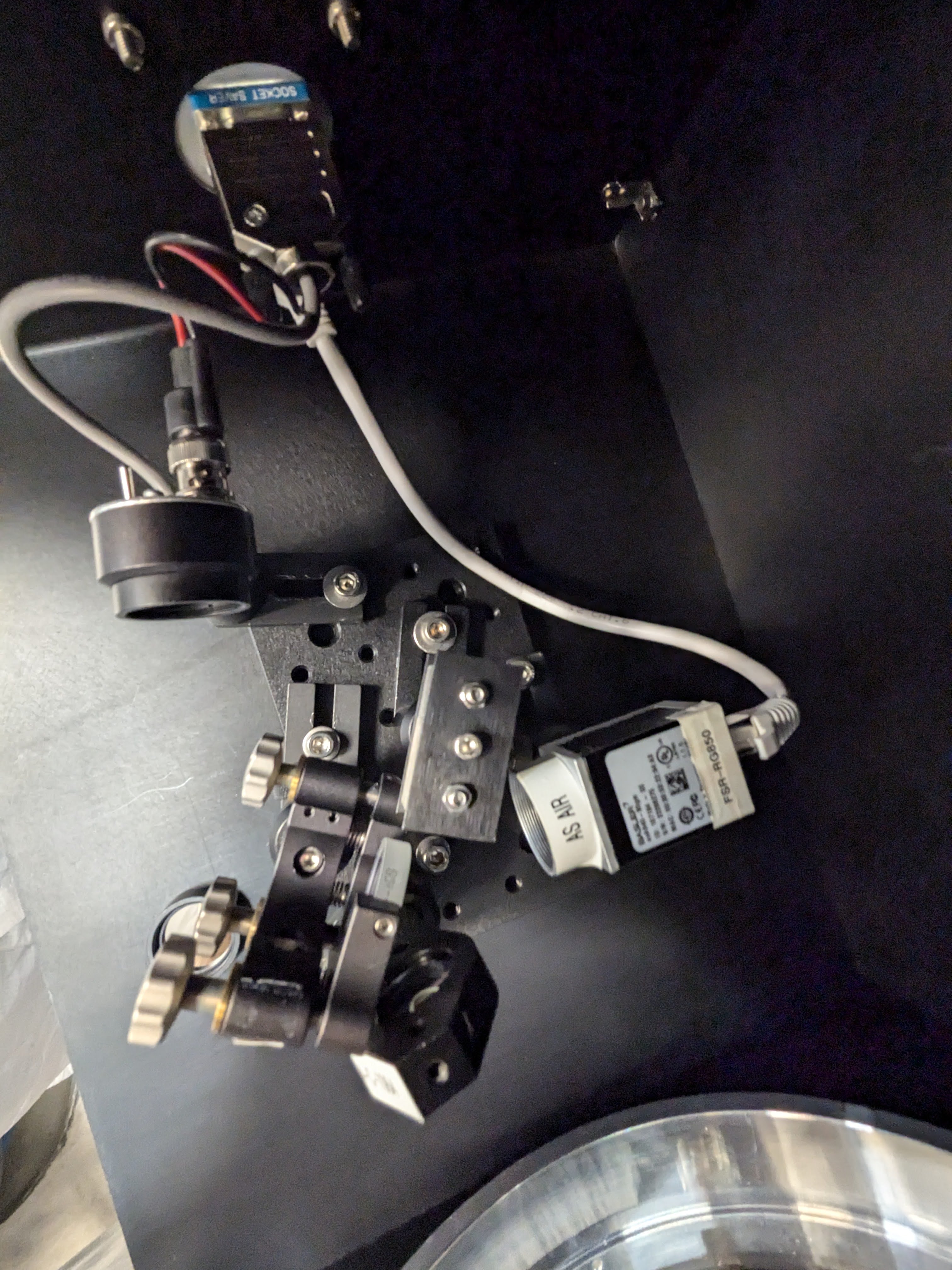
We wanted to scan the PMC through a complete FSR so we could watch the mode content while we changed the NPRO crystal temperature. To do this we unplugged the DC cables for PMC Trans and Refl from the PSL Monitoring Fieldbox and plugged them into the oscilloscope. We also plugged a cable into the 50:1 HV monitor so we could trigger off of the PMC PZT ramp. For the ramp we used the Alignment Ramp on the PMC MEDM screen, set to +/- 7V at 1 Hz. Once we got the signals on the scope and successfully triggered, we clearly had a full FSR visible so we kept these ramp settings. We watched things for a little bit before starting adjustments and noticed the laser frequency drift a little bit; Vicky estimated this at 1-3 GHz in 30 minutes.
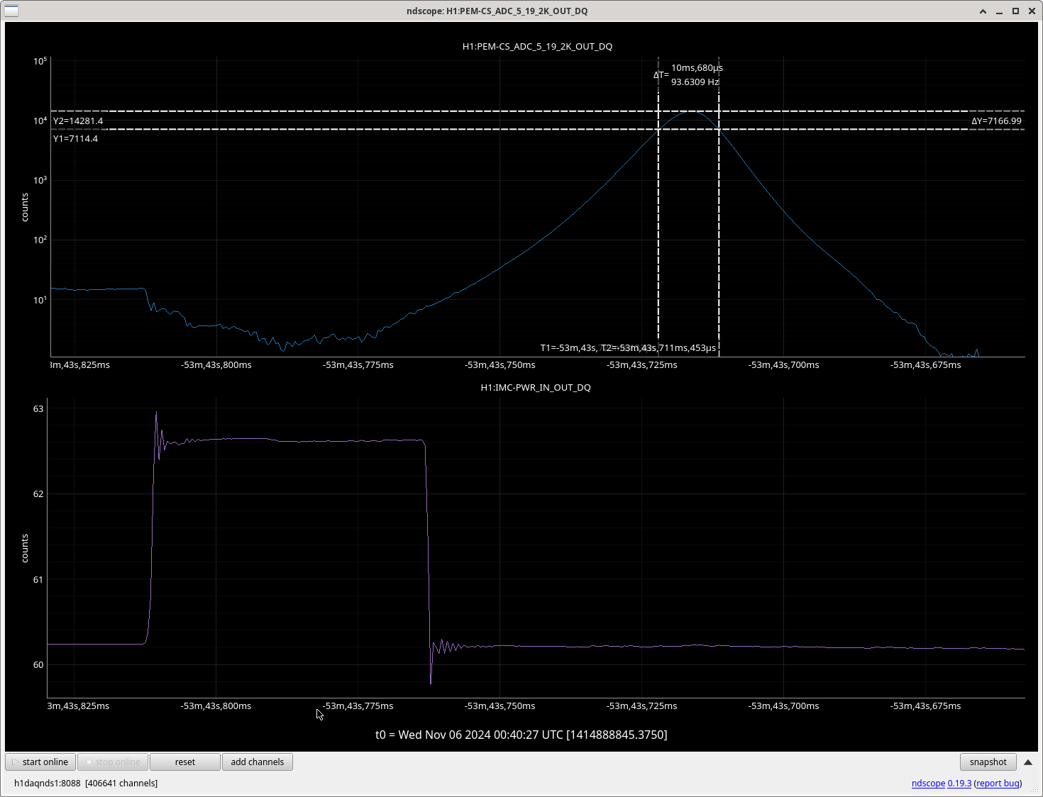
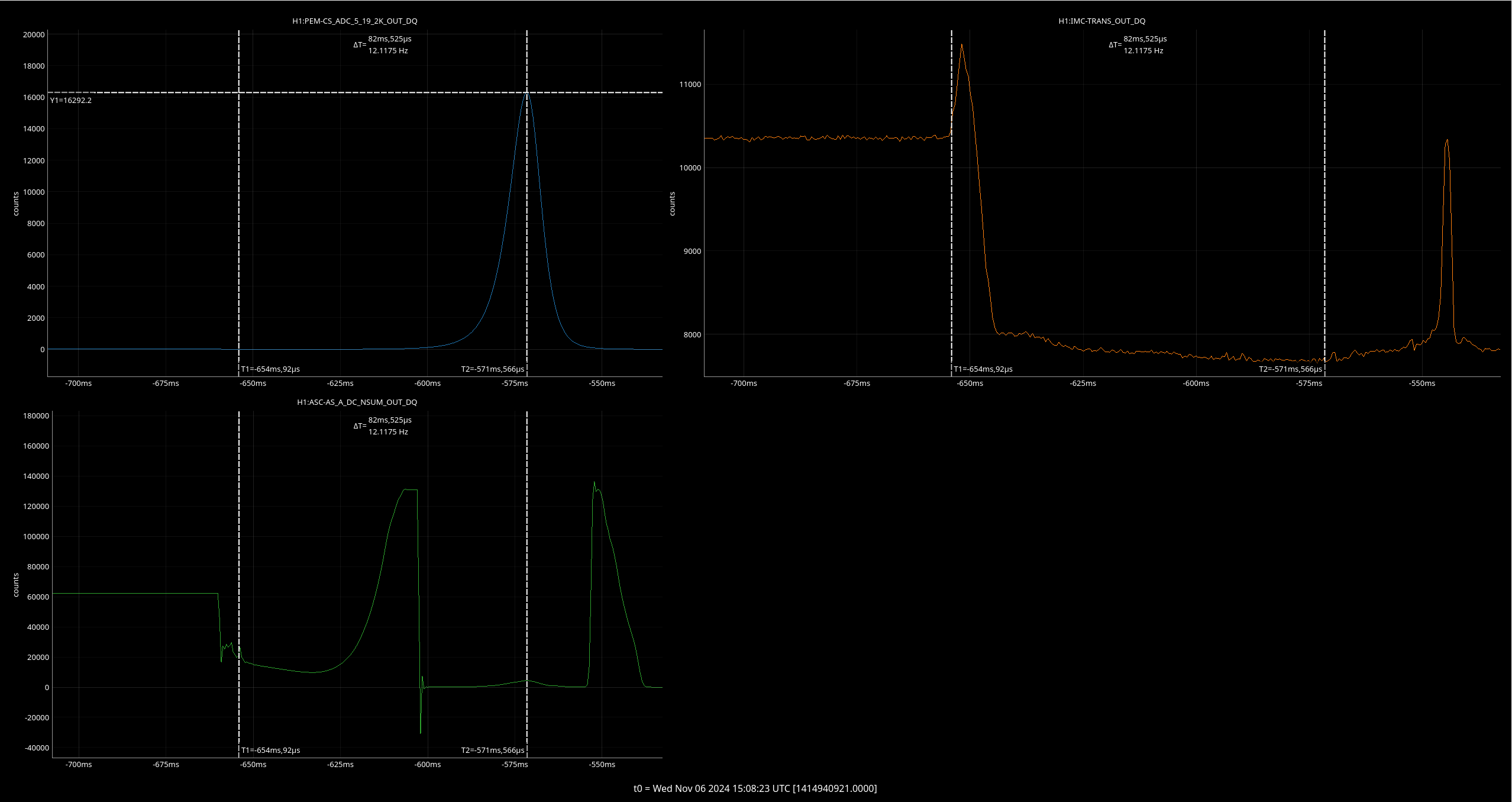
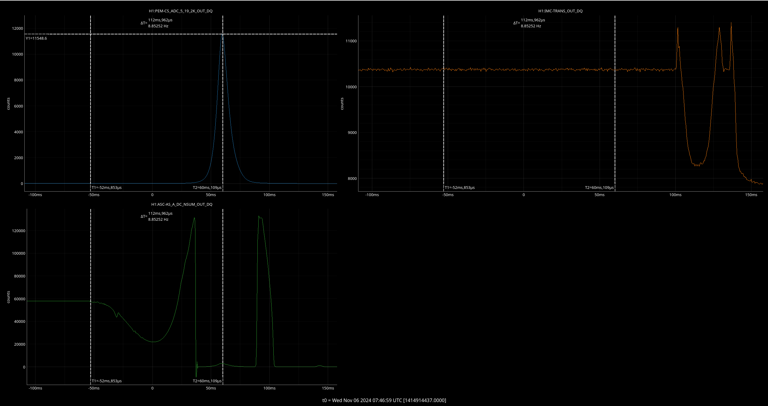
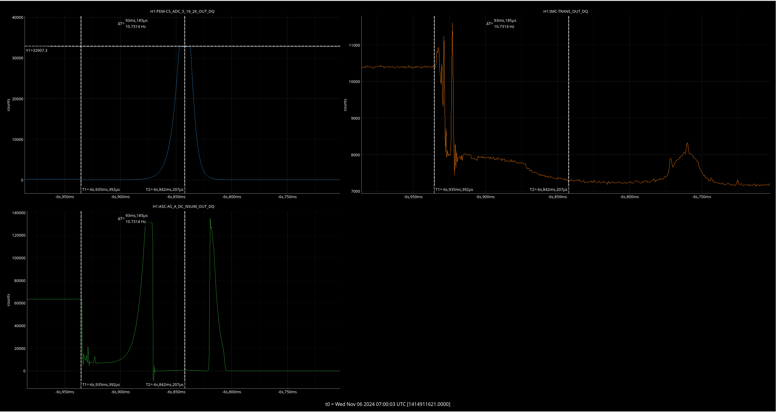
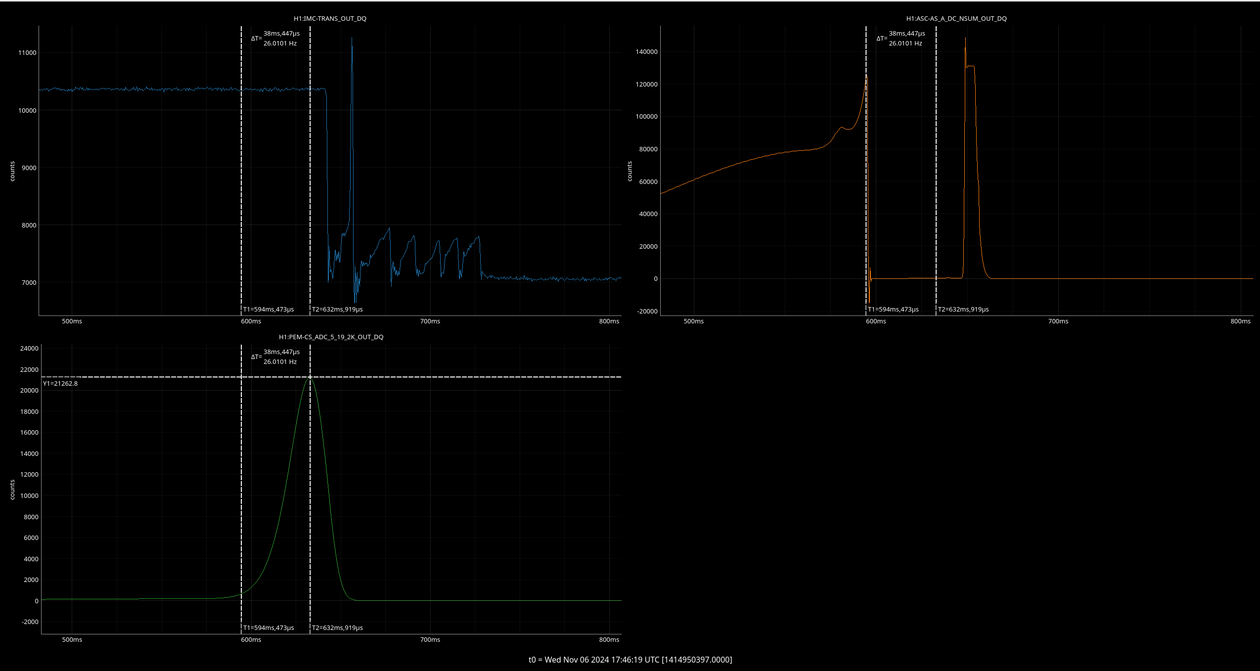
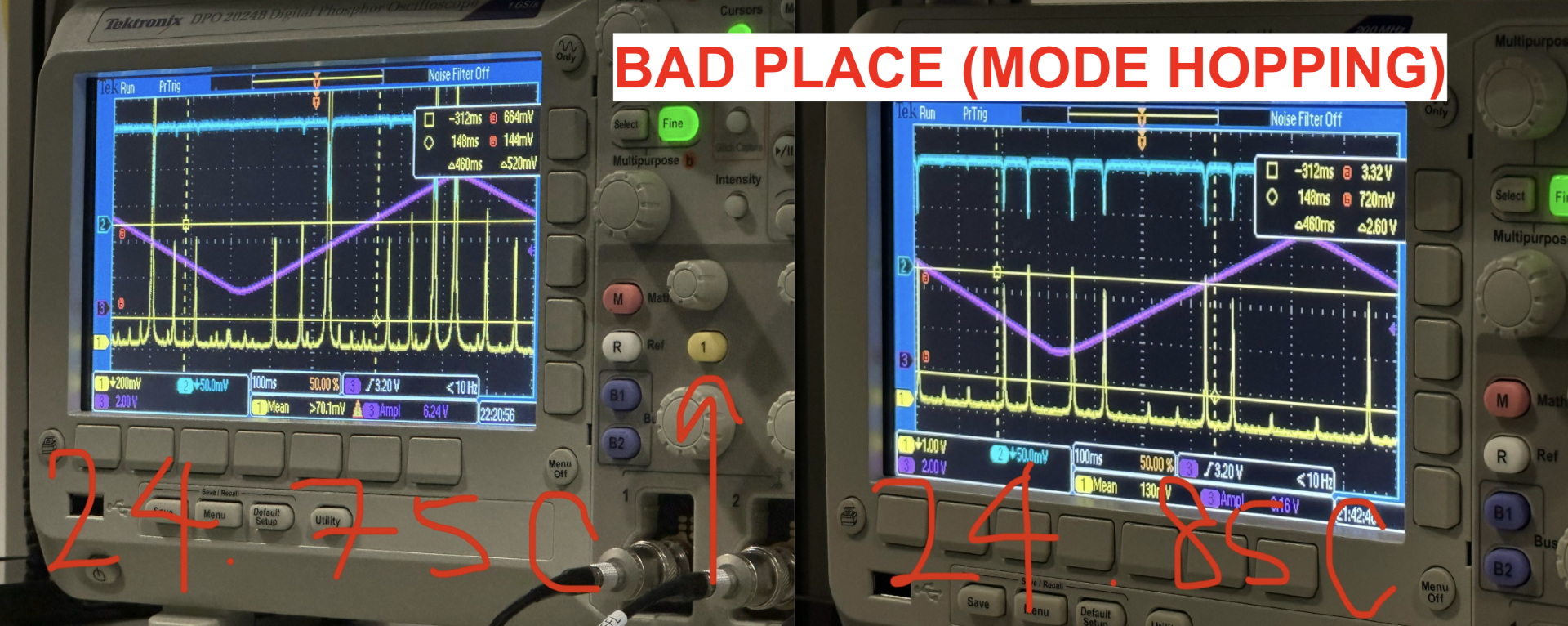
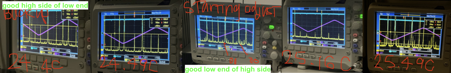
We began at the crystal temperature where we left it yesterday (25.2 °C) and used the temperature control on the FSS MEDM to step the temperature down. At ~24.85 °C we started to see clear mode hopping behavior in the scan, which got worse at 24.75 °C, see first attachment. We had originally set the crystal temperature to 24.7 °C, so clearly we started in a mode hopping region. We continued moving the temperature down to see where the mode hop region ended; the scan didn't start looking good again until ~24.5 °C. We continued moving the temperature down until we maxed the slider. This had the crystal temperature at 23.95 °C and we were still mode hop free. So we started moving the temperature up to start mapping out the upper region (>25.2 °C). When started seeing the bad mode hopping region right above 24.5 °C, so this matches with where we saw things on the way down. However, it didn't clear up until the temperature was >25.1 °C, uncomfortably close to our starting value of 25.2 °C. It looks like the spot we locked the RefCav at yesterday was right on the edge of a mode hopping region, and we had been slowly drifting in and out of it. We continued to move the temperature up via the MEDM slider unil it maxed at a crystal temperature of 25.49 °C and saw no mode hopping behavior. The second attachment shows some pictures from both of these good regions.
The slider was maxed but we wanted to continue mapping the upper region, especially as this area is closer to the operating temperature of the NPRO we just removed from the PSL (meaning the SQZ and ALS lasers had been happily locked in this area for all of O4 to date). To do this we set the slider back to 0 (a crystal temperature of ~24.7 °C) and used the knob on the front panel of the NPRO power supply to adjust the crystal temperature. We moved slowly while watching the power out of the amplifiers and NPRO, in case the temperature adjustment caused beam changes that had a negative effect on amp output. In this way we moved the crystal temperature up to 26.75 °C and saw no mode hopping behavior. We did, however, start to see the power out of the amplifiers drop a little. At a crystal temperature of 26.75 °C we lost roughly 3 mW from the NPRO, ~0.5 W from Amp1, and ~1 W from Amp2. 3 mW from the NPRO results in about 0.25 W lost at Amp2, so most of the loss is likely due to mode changes in the NPRO beam caused by the different operating temperature (if this was alignment we would have lost power a good bit faster, mode matching changes I've observed are generally a good deal slower than alignment changes). Because of this we stopped here, and set the crystal temperature to ~26.27 °C. Still had ~139.0 W output from Amp2, so all is well here.
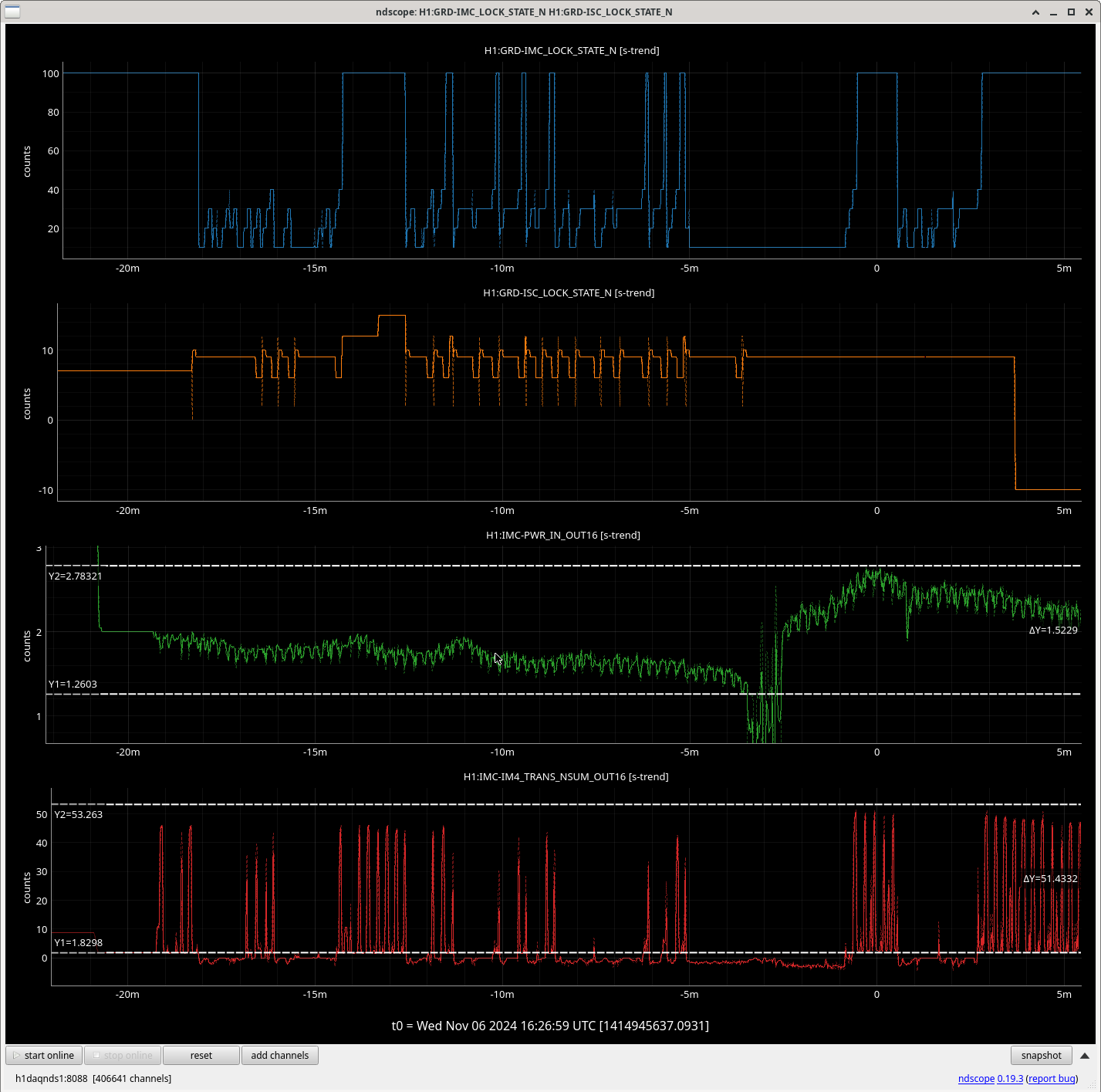
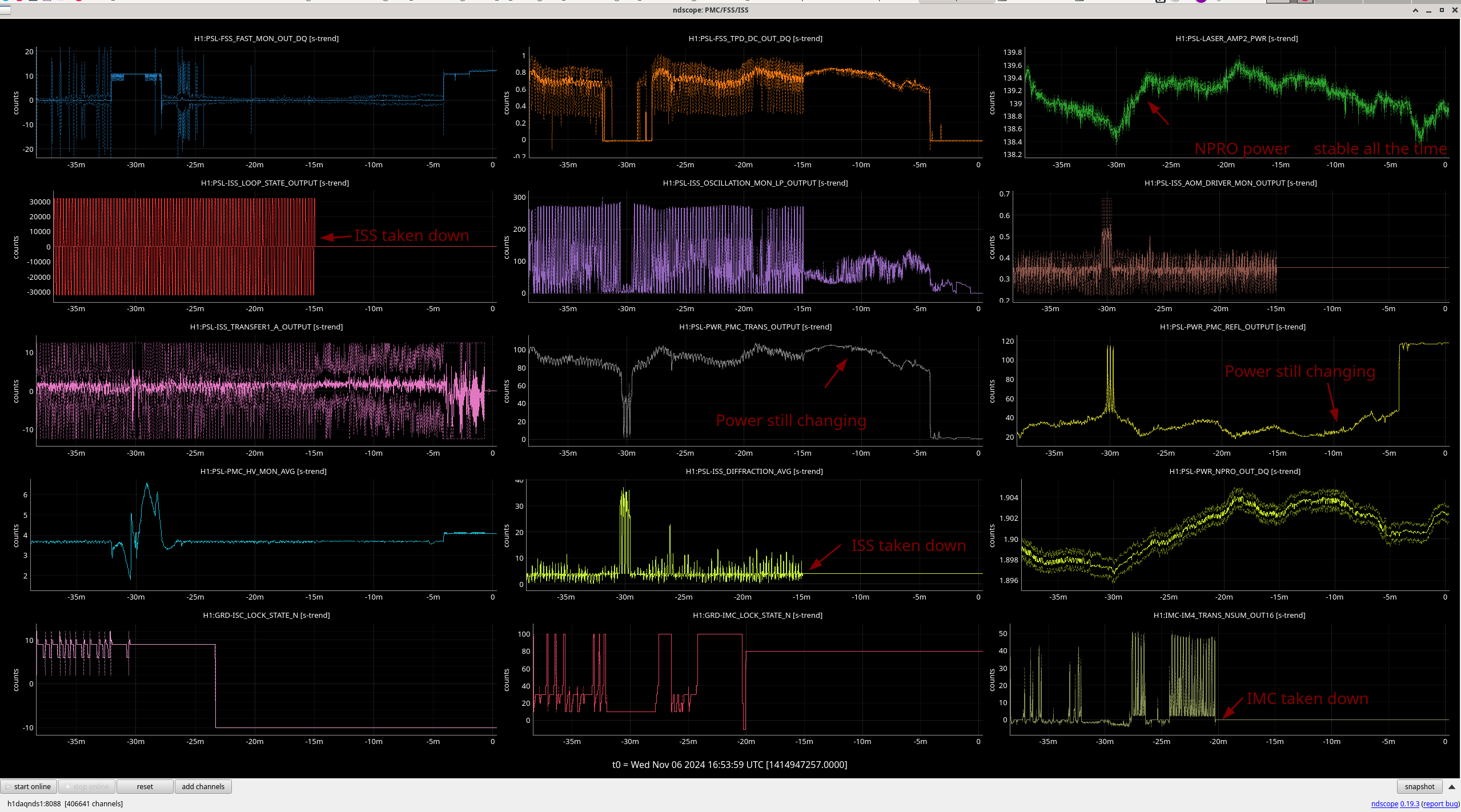
We then plugged everything back in and relocked the PMC; it locked without issue. We then adjusted the crystal temperature down via the MEDM slider to find a RefCav resonance. We did have one time where the PMC unlocked when the PZT ran out of range (the PMC PZT moves to keep the PMC locked while the laser frequency changes). We couldn't see a 00 coming through on the PMC ramp, so we moved the crystal temperature back up until a 00 was clearly visible flashing through; at this point the PMC locked without issue. Continuing to move the temperature down we found a RefCav resonance flash through at a crystal temperature of 26.26 °C, so we locked the RefCav. It took a couple of passes to grab the lock (had to disable the FSS Guardian to keep it from yanking the gains around), but it did lock. The final crystal temperature was 26.2 °C. To finish we locked the ISS, grabbed our equipment, and left the LVEA.
We left things here for an hour and saw no signs of mode hopping again, so Daniel and Vicky started tuning the ALS and SQZ lasers to match the new NPRO frequency. Time will tell whether or not we are in a better place in regard to NPRO mode hopping, but results so far are promising.
Daniel, Vicky - We adjusted the SQZ + ALS Y/X laser crystal temps again to match the new PSL laser frequency:
- SQZ: 27.05 C --> 26.08 C
- was +2.934 GHz.
- Had to revert yesterday's laser current change 81079 to avoid mode-hopping at this new temp.
- So today current changed 1.885 A --> 1.936 A
- After, SQZ PMC transmisison is back to normal ~690 (yesterday it was low ~650)
- ALS Y: 28.8(?) C --> 27.92 C
- was +2.8 GHz.
- Issues:
- Reduced laser current 1.635 A --> 1.60A to avoid ALS Y mode-hopping at this new temperature.
- The laser crystal temperature knob is very bad, temp adjustment is difficult. Readback temp jumps around a lot as the knob is turned even very slightly. Makes tuning out of a mode hop region very difficult.
- ALS X: 25.45 C --> 26.40 C
- was -3.162 GHz. Adjustment was easy.
----------------------------------------------------------------------------------------------------------------------------------
Record of aux laser crystal temp changes following PSL swap:
- 80922: 1st adjustment for O3 spare PSL freq (last week, PSL was likely mode-hopping last weekend)
- SQZ: 24.83 C --> 26.30 C
- ALS Y: 28.59 C --> 30.05 C
- ALS X: 24.8 C --> 26.62 C
- 81074: 2nd adjustment for O3 spare PSL freq (yesterday to avoid weekend mode-hopping, but PSL was likely intermittently mode-hopping last night)
- SQZ: 26.31 C --> 27.02 C
- ALS Y: 30.05 C --> 28.85 C (after un-clamping current)
- ALS X: 26.62 C --> 25.44 C
- Here, 3rd adjustment for O3 spare PSL freq (today to tune PSL laser crystal temp further out of mode-hop free region, tuning PSL laser freq back to original O4 freq).
- SQZ: 27.05 C --> 26.08 C (1.936 A)
- ALS Y: 28.8_ C --> 27.92 C (1.60 A)
- ALS X: 25.45 C --> 26.40 C
Vicky, Camilla. Repeated what Vicky did yesterday 81079 to get the OPO temperature back (these are instructions for when the temperature starts very far away):
- Toggled CLF to SEED in.
- Locked PMc and SHG, took SQZ_OPO_LR to LOCKED (locks on GREEN)
- Adjusted temperature to maximum seed signal with OPO_IR_PD_LF_OUT, got a bit confused here, either went past the best temp or locked on a 2nd order mode.
- Toggle to CLF and re-optimize, we got OPO_IR_PD_LF_OUT to ~200e-6 and CLF RF6 increased to -13.
We then took SQZ_MANAGER to DOWN and FDS_READY_IFO. Got there with no issues, we'll want to re-optimize the temperature right before we go to observing.
Starting OPO temp: 31.25. Ending temp: 31.42, this is closer to the temperature we had straight after the NPRO swap.