TITLE: 10/21 Day Shift: 1430-2330 UTC (0730-1630 PST), all times posted in UTC
STATE of H1: Commissioning
INCOMING OPERATOR: TJ (remote)
SHIFT SUMMARY:
IFO is in NLN and COMISSIONING as of 14:40
A lot happened today, mostly related to two brief power outages taking down a few systems. Here's the summary (times in UTC).
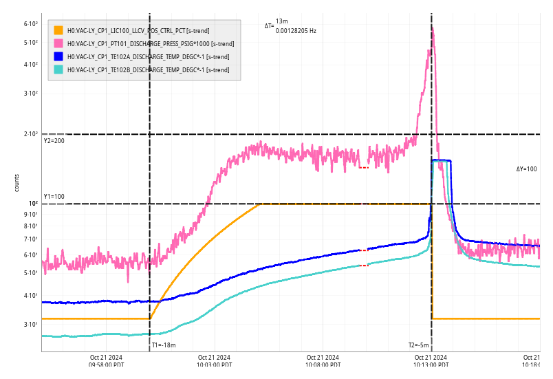
Power Outage Story Start (alog 80791)
Pre-Shift:
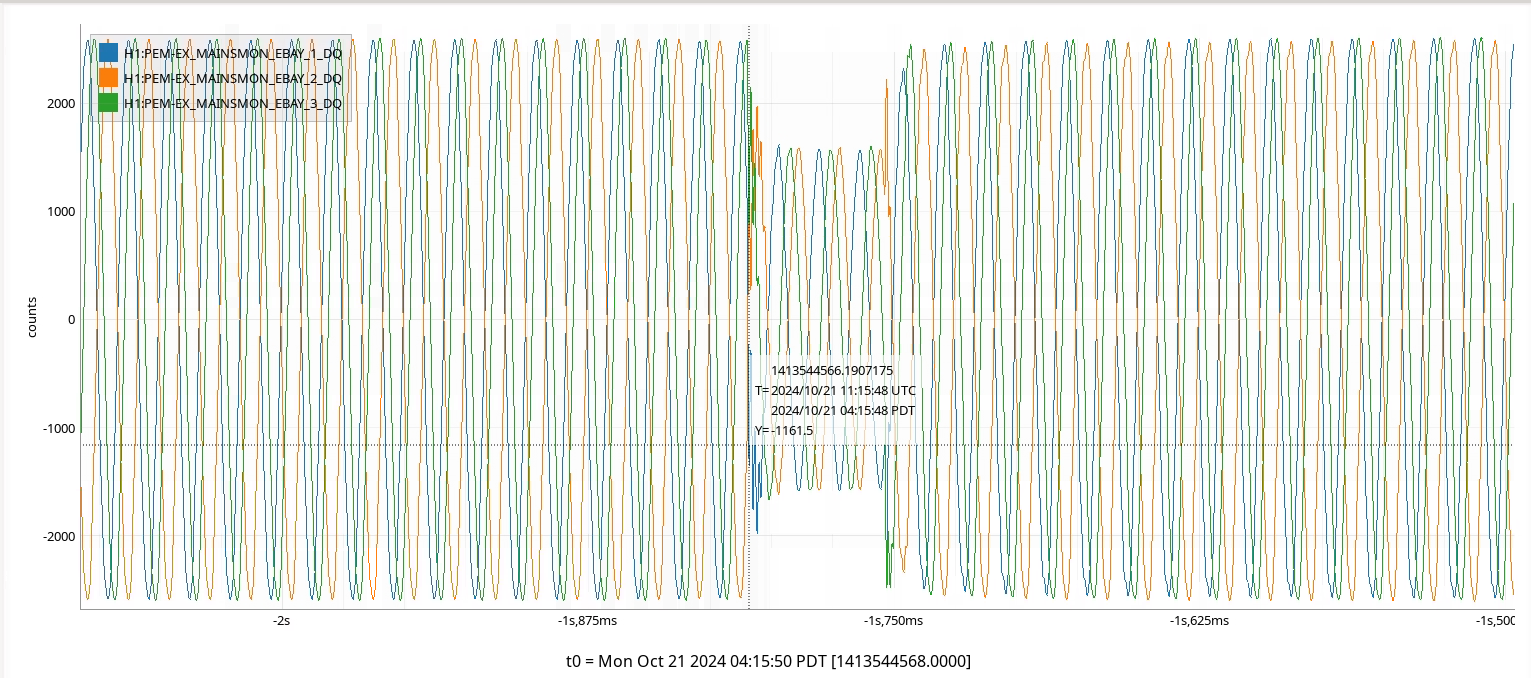
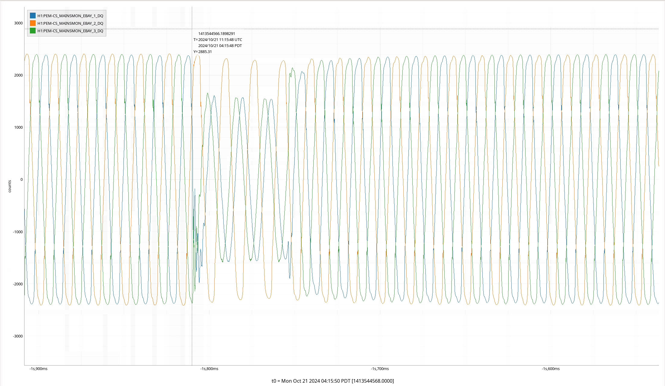
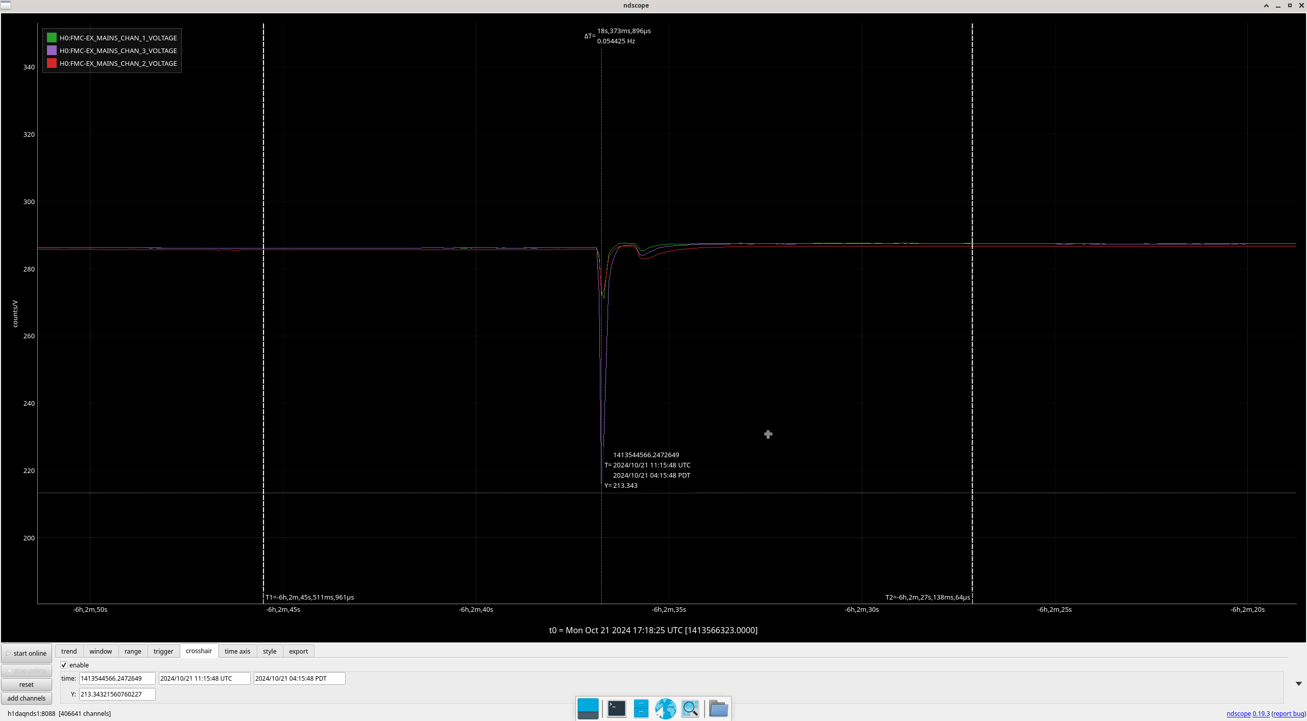
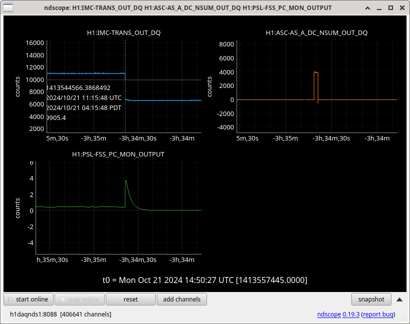
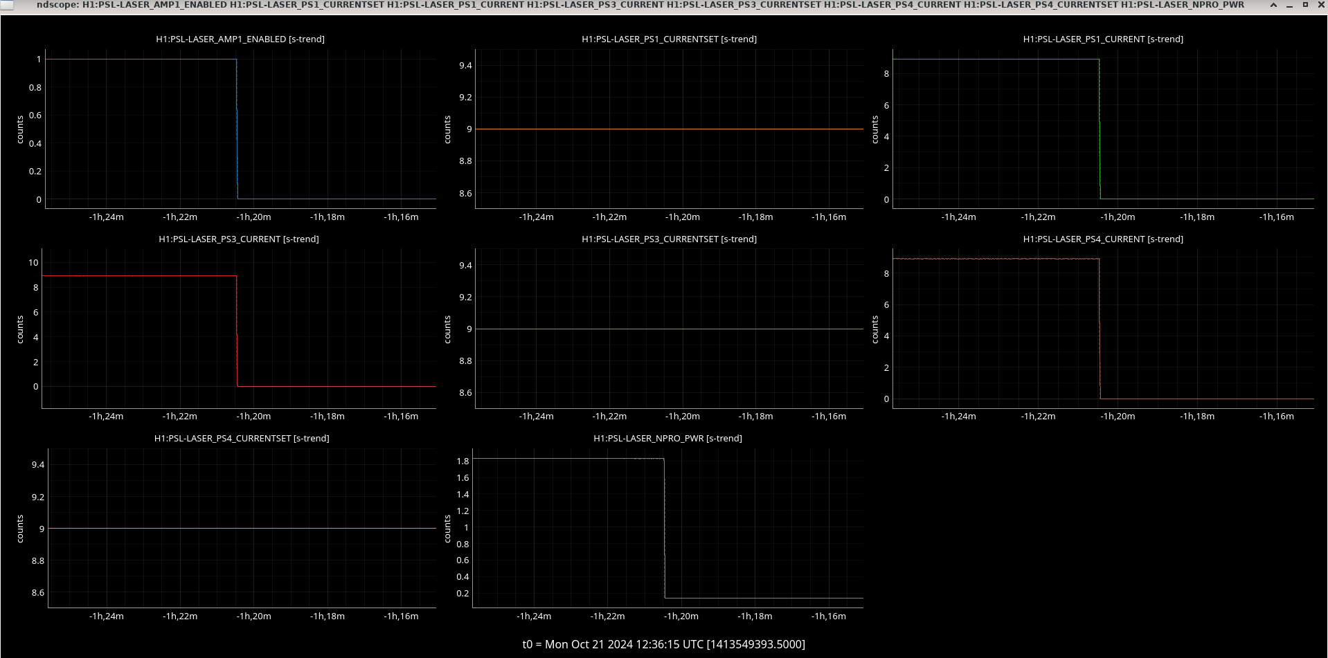
11:15:48 Local: PSL downed (PMC High Voltage, HAM6 PZT High Voltage, NPRO tripped), Ryan called after 15 mins in READY. Ryan C and Jason troubleshoot, figuring out that it can’t be fixed remotely. OWL alog 80782 They hopefully go back to sleep. IFO in MAINTENANCE.
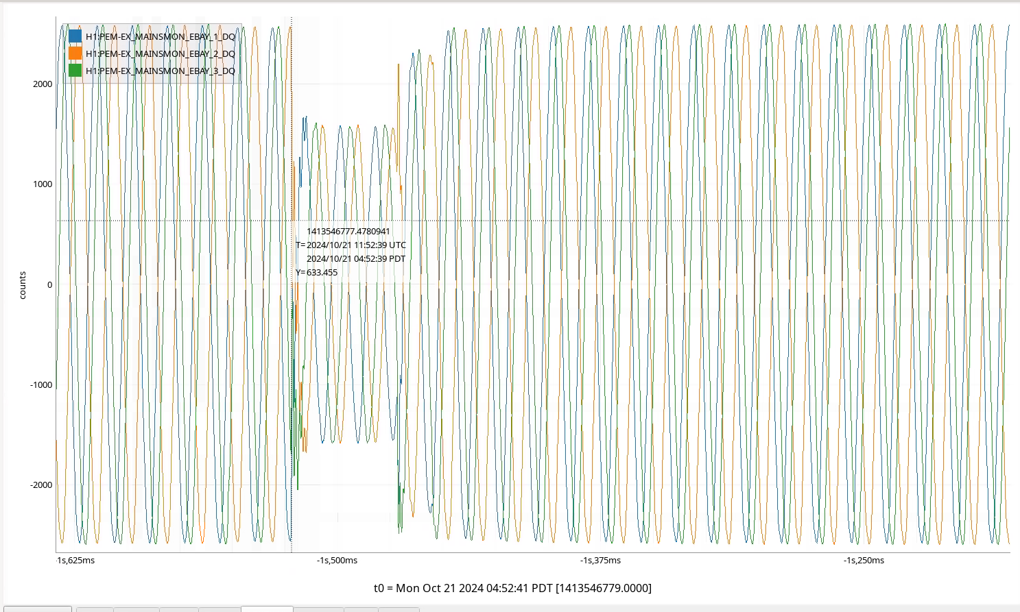
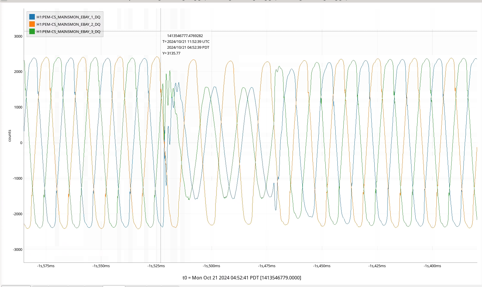
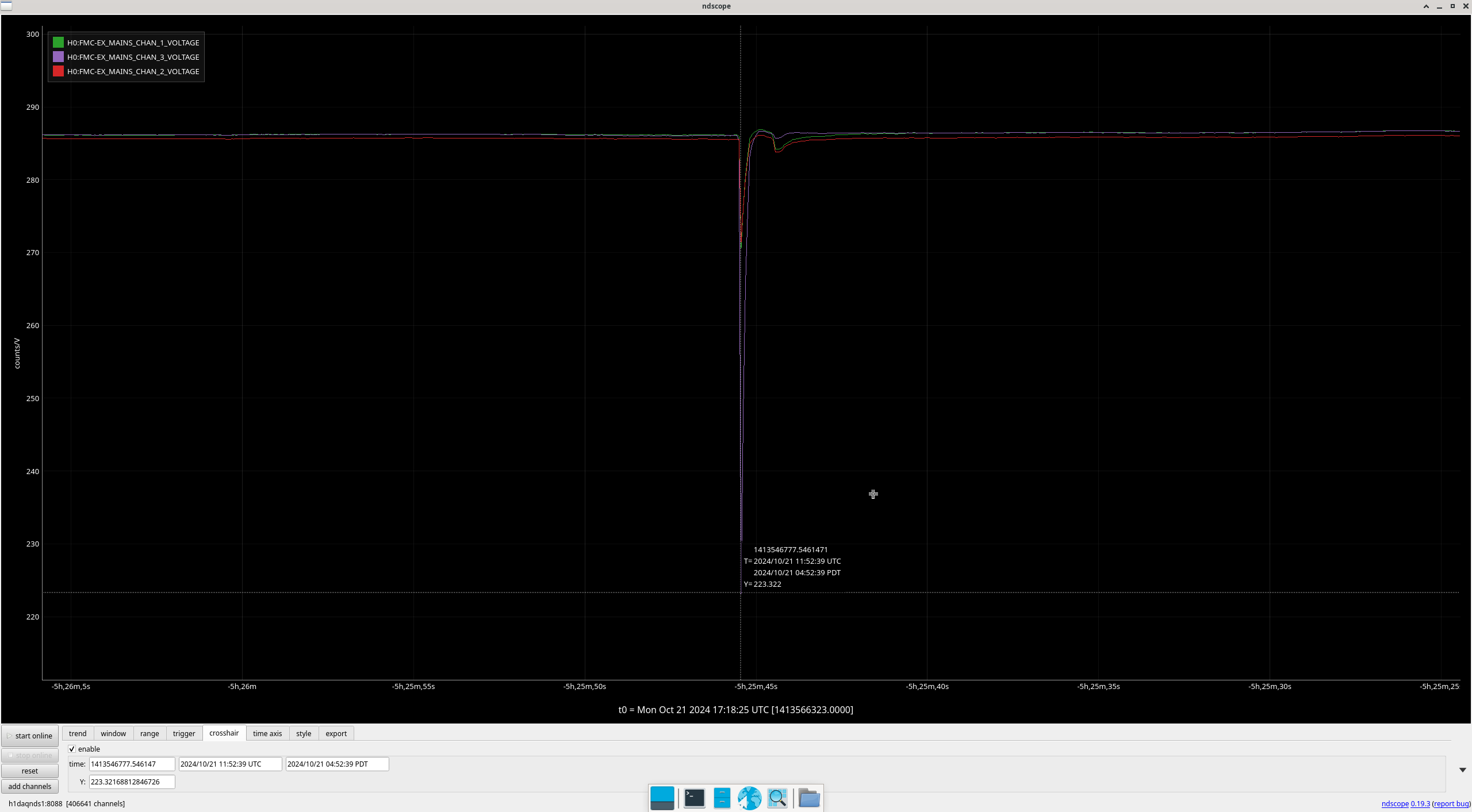
11:52 Local: Power Glitch 2, the sequel. IFO can’t lock, stays downed.
Shift Start:
14:30: I arrive and realize the PSL has no power and that NDS is being slow. I read the alog and mattermost and saw that Ryan C (OWL Ops) was called and troubleshooting.
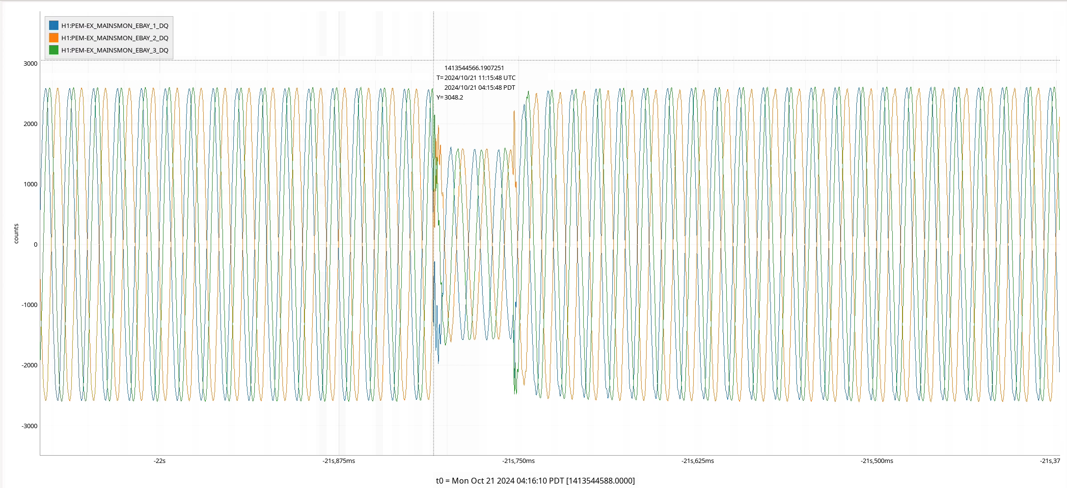
14:45: Dave gets on TS and figures out that it was indeed a power glitch (alog bla bla) that took down 2 front end channels, the PMC Hi-Voltage, the NPRO (tripping), HAM6 PZT and potentially caused some NDS troubles. Confusion ensued about what should and shouldn’t have gone down over such a glitch.
15:00: Jonathan joins, goes into the MSR and checks the UPS, and confirms that this had gone on battery for the 2 outage times. This further confirms us that there was definitely bad sitewide power, so it went on battery back-up.
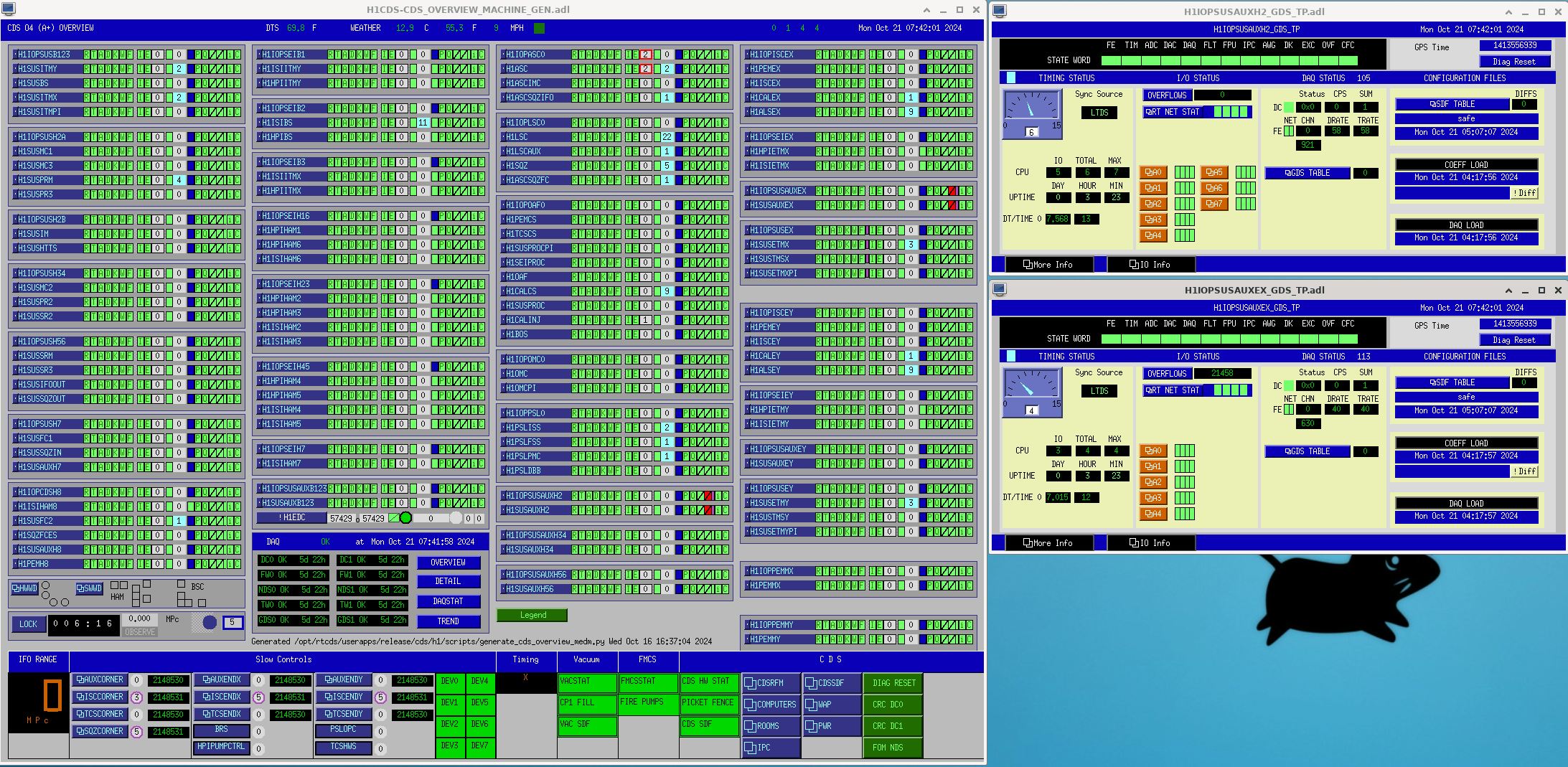
15:00: By now, Dave and Jonathan have understood the outage effects apart from 2 front-end channels going down during the outages, and auto-rebooting shortly thereafter. The two culprits are SUSAUXH2, SUSAUXEX. These aren’t on the UPS so CDS is still confused as to why those went down. Dave cleared the CDS overview alerts and CDS is investigating.
15:05: Fil joins and turns the HAM6 PZT and PMC Hi-Voltage back on.
15:10: Ryan S joins and turns on the PSL, allowing us to lock.
Power Outage Story End, Normal Locking Start:
15:25 Guardian begins initial alignment but FSS glitch (unrelated rabbit hole) happens so we relock the IMC and continue.
16:00 Initial alignment ends and we begin locking! High guardian state LL and alignment issues requiring initial alignment happen, delaying us further (but not for too much longer!)
18:07: NLN Acquired, IFO OBSERVING
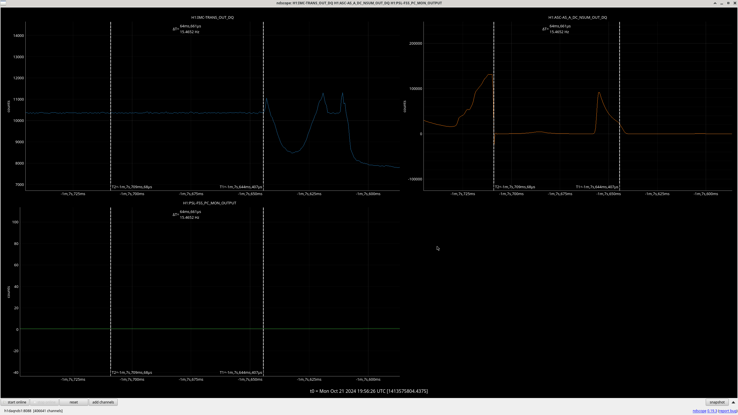
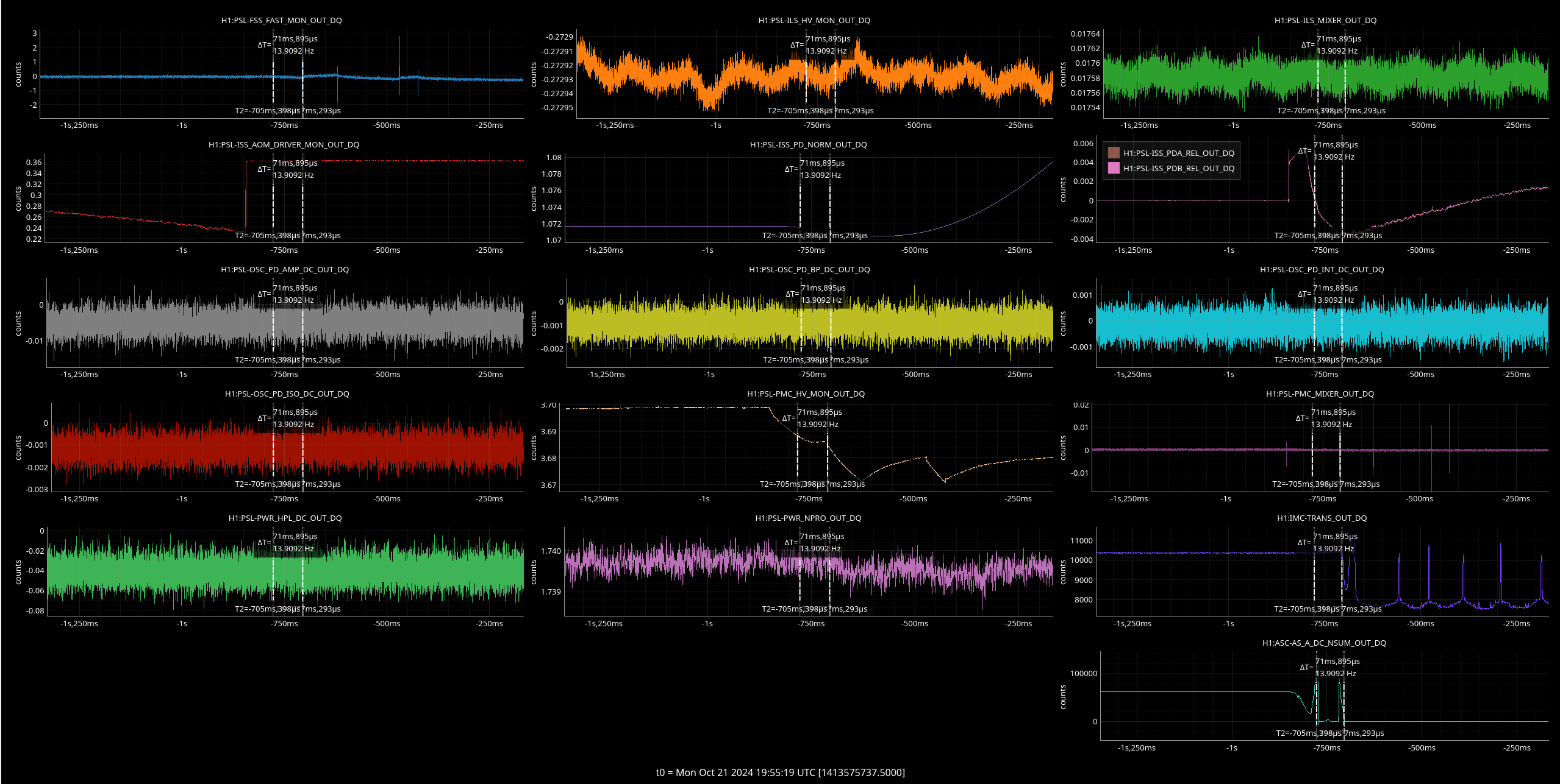
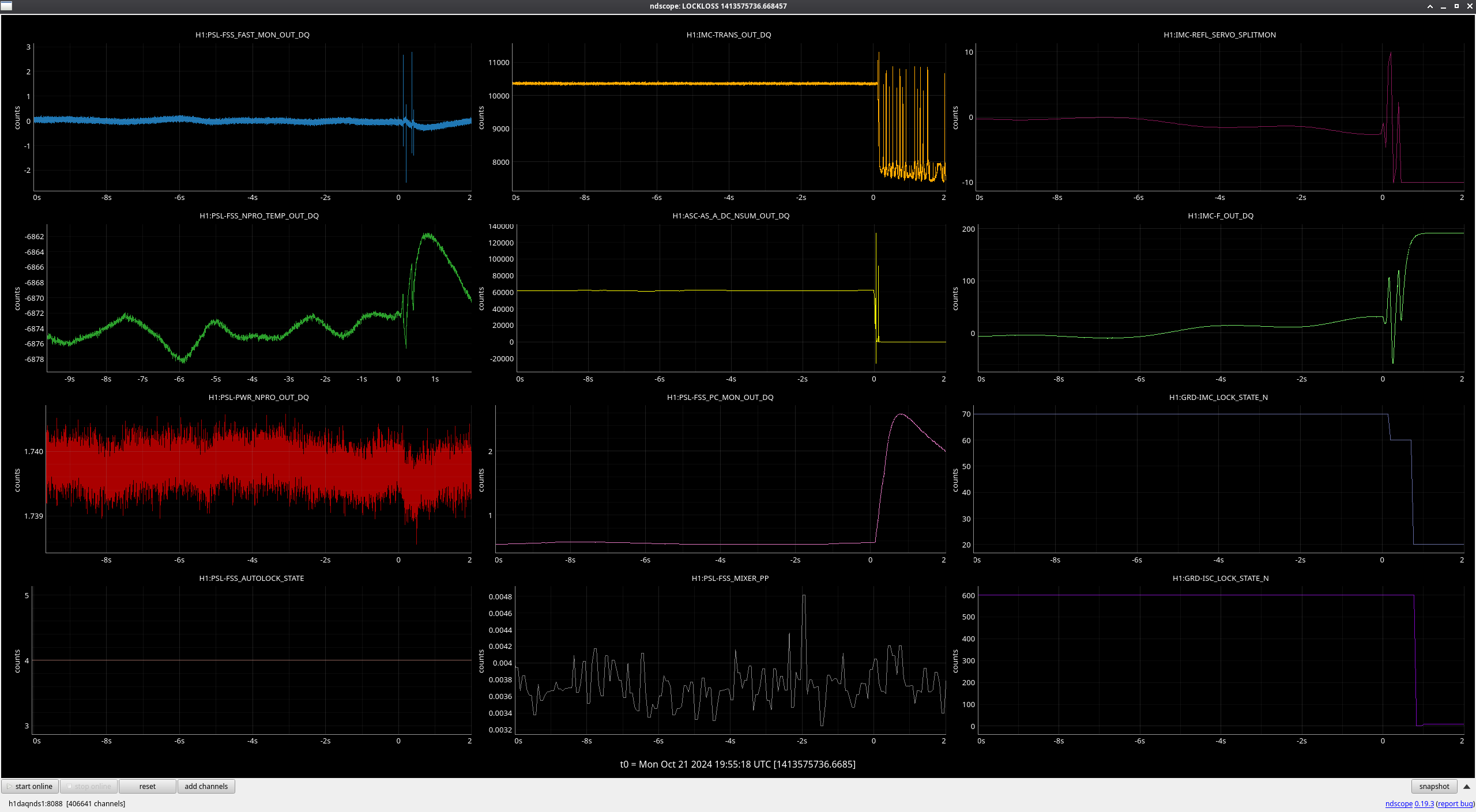
19:55: Lockloss alog 80798 (Not PSL, unknown cause).
21:15: Trucks on the move in prep for Earthmoving.
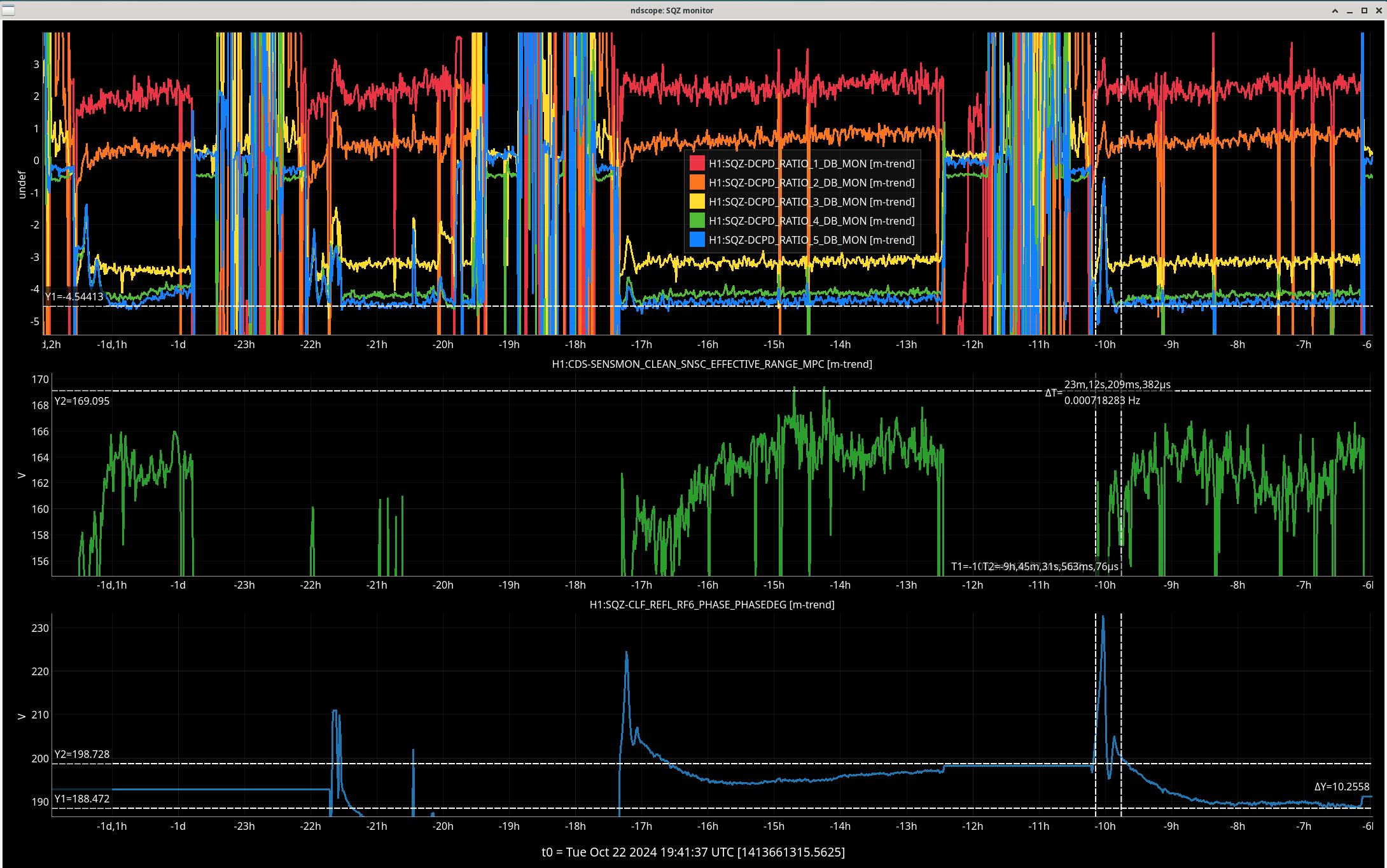
21:40: NLN Acquired, IFO COMISSIONING
23:30: Shift End, Still comissioning
LOG:
| Start Time |
System |
Name |
Location |
Lazer_Haz |
Task |
Time End |
| 16:36 |
SAFE |
HAZARD |
LVEA |
YES |
!!!!!LVEA IS LASER HAZARD!!!! |
03:16 |
| 17:39 |
FAC |
Karen |
MY |
N |
Technical cleaning |
17:39 |
| 17:39 |
FAC |
Karen |
Wood Shop |
N |
Technical Cleaning |
17:56 |
| 18:25 |
PSL |
Jason, Ryan S |
Optics Lab |
Local |
Preliminary PSL Optics Reconnaissance |
18:42 |
| 21:25 |
FAC |
Earth Movers (TM) |
Staging Building Behind |
N |
Earth Move Prep |
22:25 |
| 21:26 |
PSL |
Jason, Ryan S |
Optics Lab |
Local |
Spare NPRO Work |
22:26 |