J. Oberling, R. Short, M. Pirello, F. Clara, F. Mera
Summary: We're pretty much back where we started, not sure where the problem is but sure there is a problem somewhere.
Since mid-September there have been an increasing number of glitches in the FSS. These are seen in the FAST channel (signal to NPRO PZT), the PC channel (signal to phase-correcting EOM), and the TEMP channel (NPRO crystal operating temperature). In addition, these glitches are the suspected cause of many locklosses in the last couple of weeks and have delayed relocking due to these glitches causing FSS oscillations. In light of this we took a look at the FSS today.
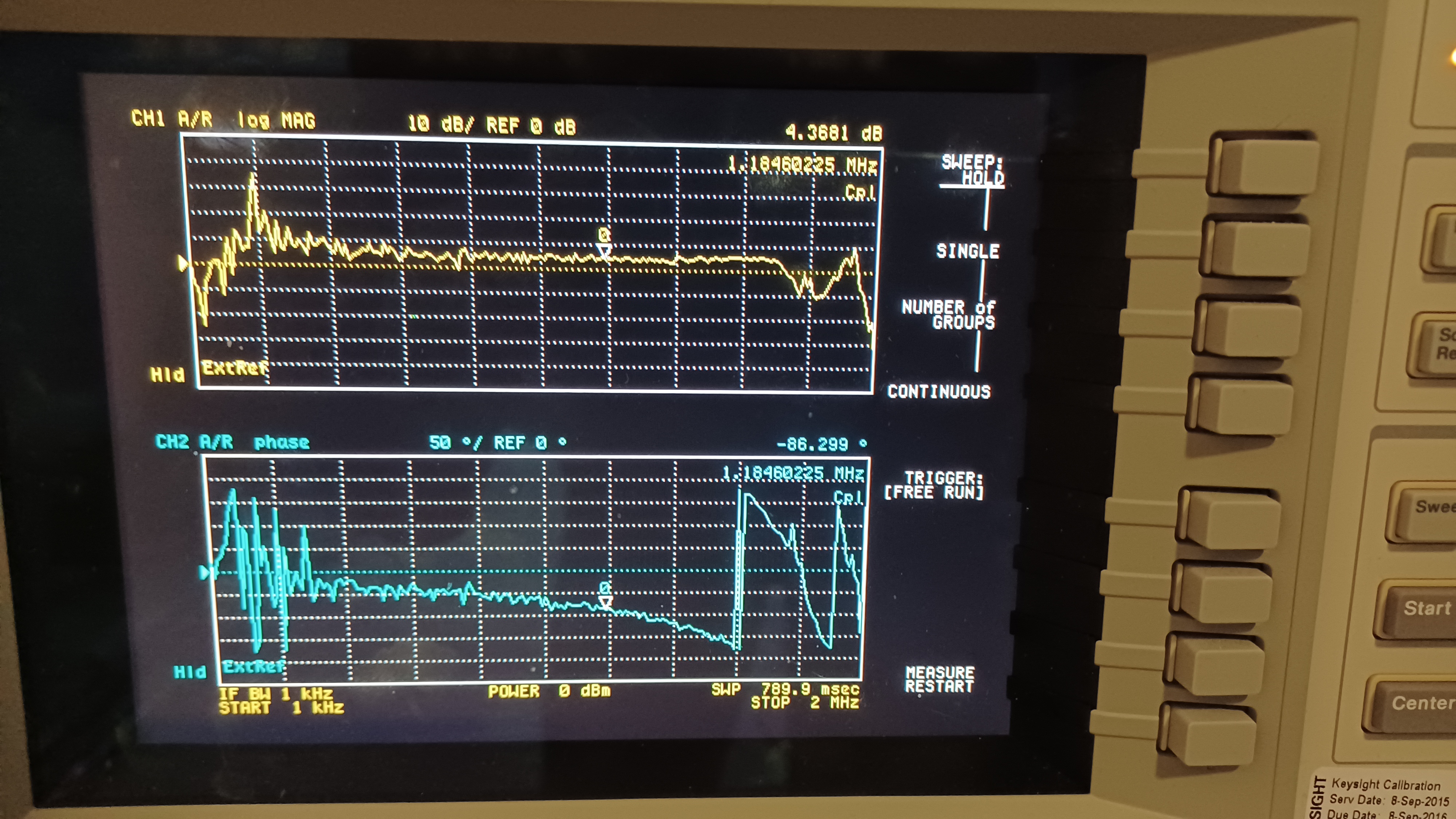
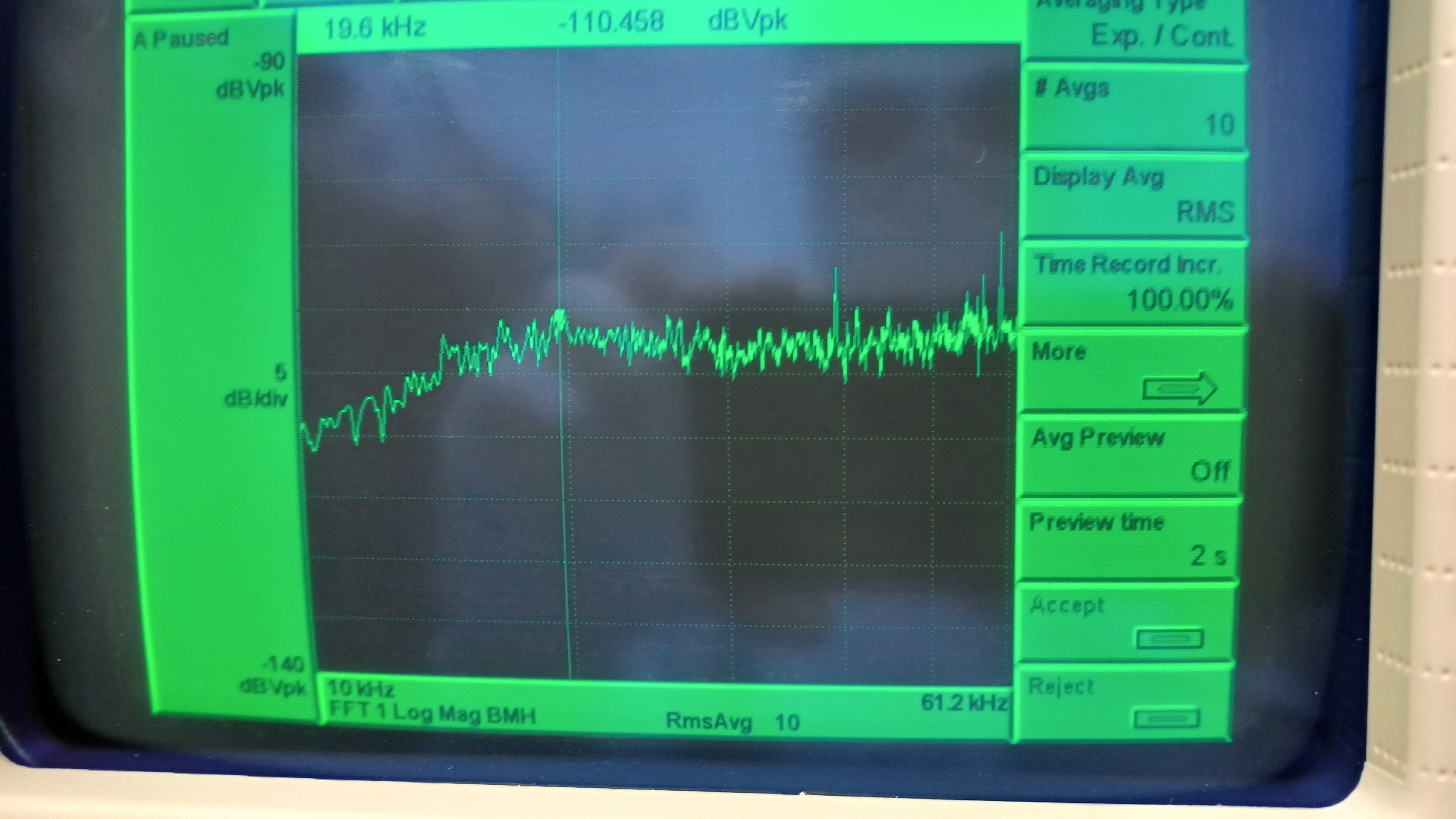
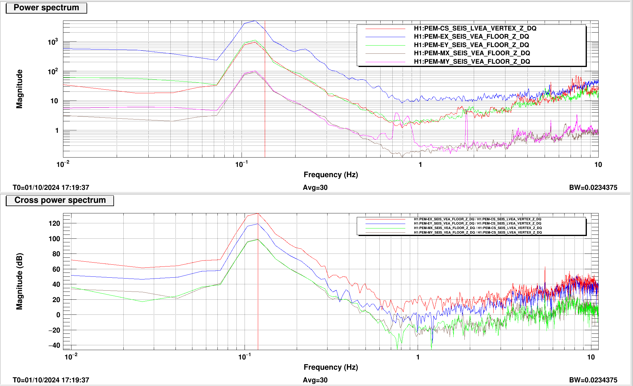
At the start of maintenance we unlocked the IMC, leaving the FSS locked to only the Reference Cavity (RefCav). I tweaked up the alignment then went out on the floor with Fernando and Ryan to take a look at the FSS transfer function. I set up the Agilent network analyzer as normal, but the TF looked like garbage; I had to up the source power to 0 dBm (from our usual -20 dBm) to get a clear signal, and still the TF looked wrong. See first attachment. Seeing this, we filed a WP (12114) and pulled the TTFSS box from the PSL enclosure and took it to the EE shop.
The current TTFSS is old, and we were unable to find a test plan for it. With Marc, Fil, and Fernando we began stepping through the circuit diagram, testing each component to make sure it was functioning as expected from the diagram (for example: "The gain should be x, is it? No, but we might be injecting too high a frequency, see the filter in the feedback? Lower the frequency, now is the gain OK? Yes."). This was somewhat time consuming, but we could find no single component that was clearly bad or not operating properly. Visually everything looked ok, nothing was obviously blown or damaged. Marc did clean some excess flux from some of the solder pads. We then checked the LO and everything looked OK there as well; signal amplitude might be a little high but Fil didn't see anything worrisome. Not knowing what else to do, I reinstalled the TTFSS box.
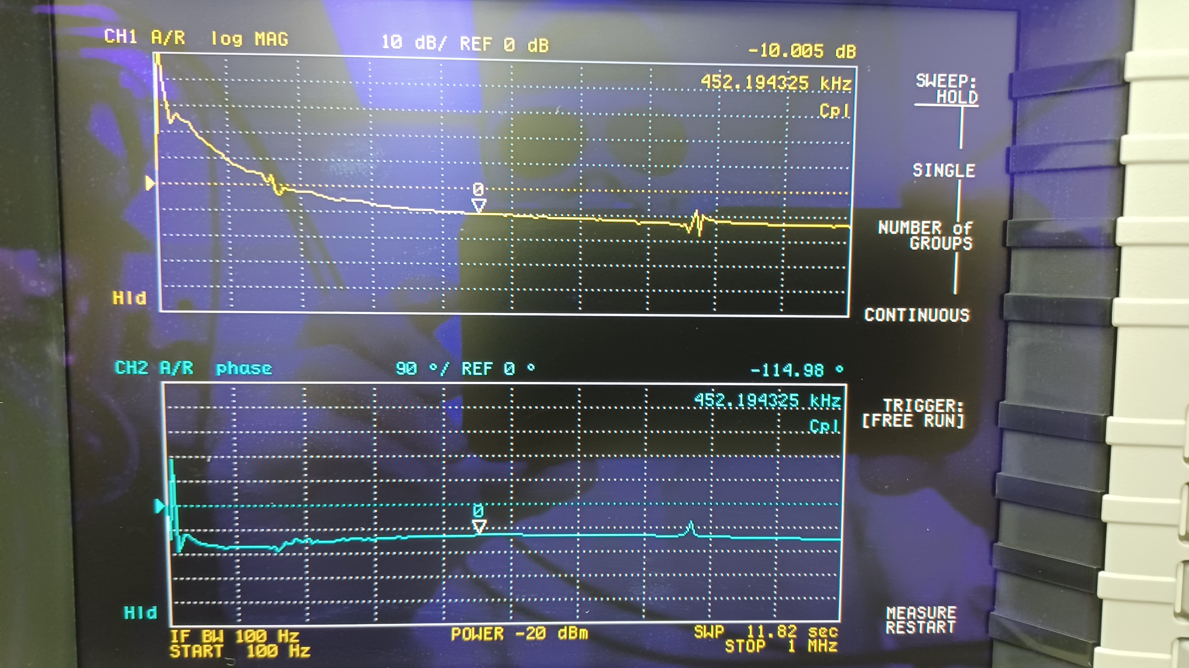
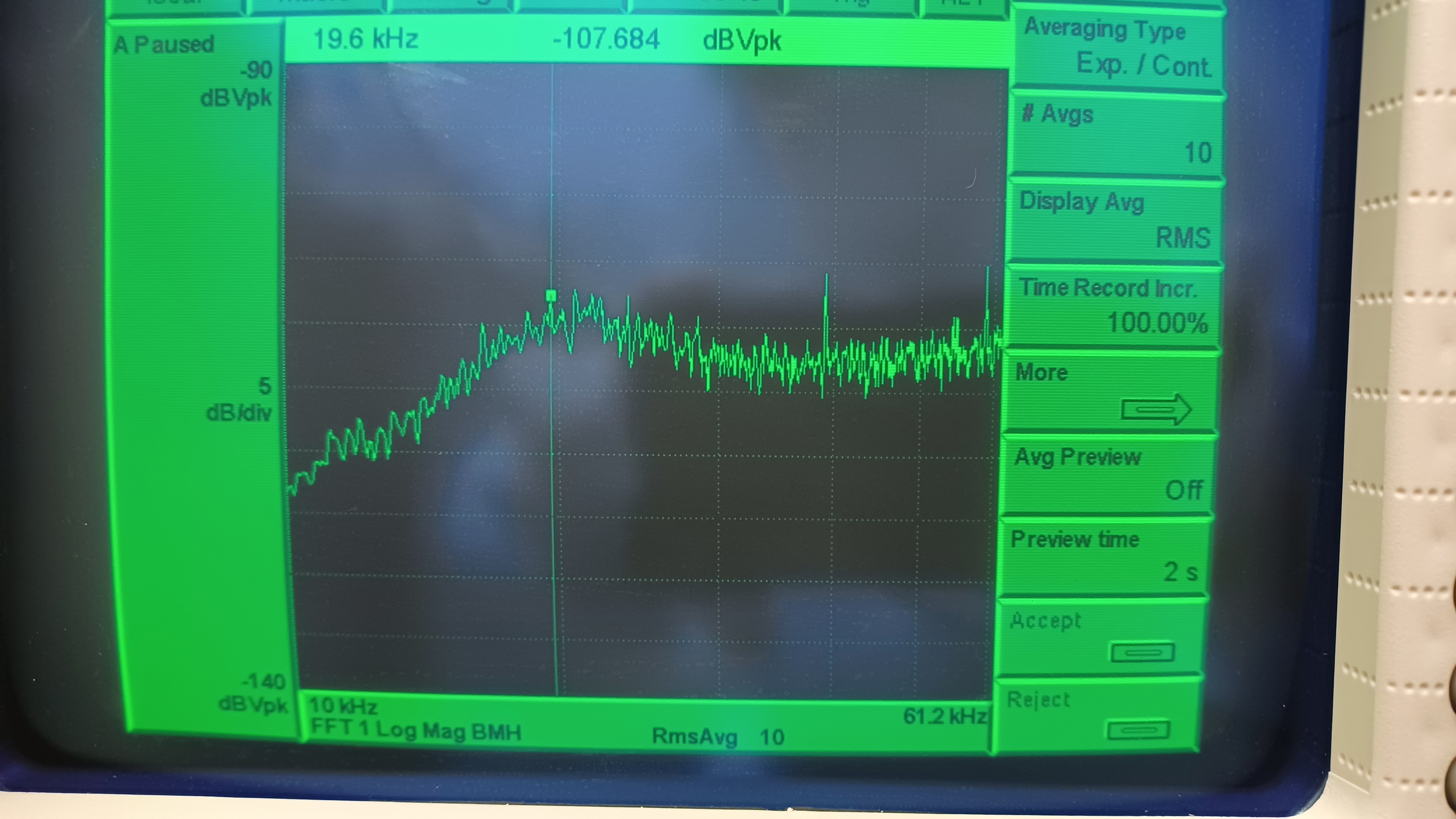
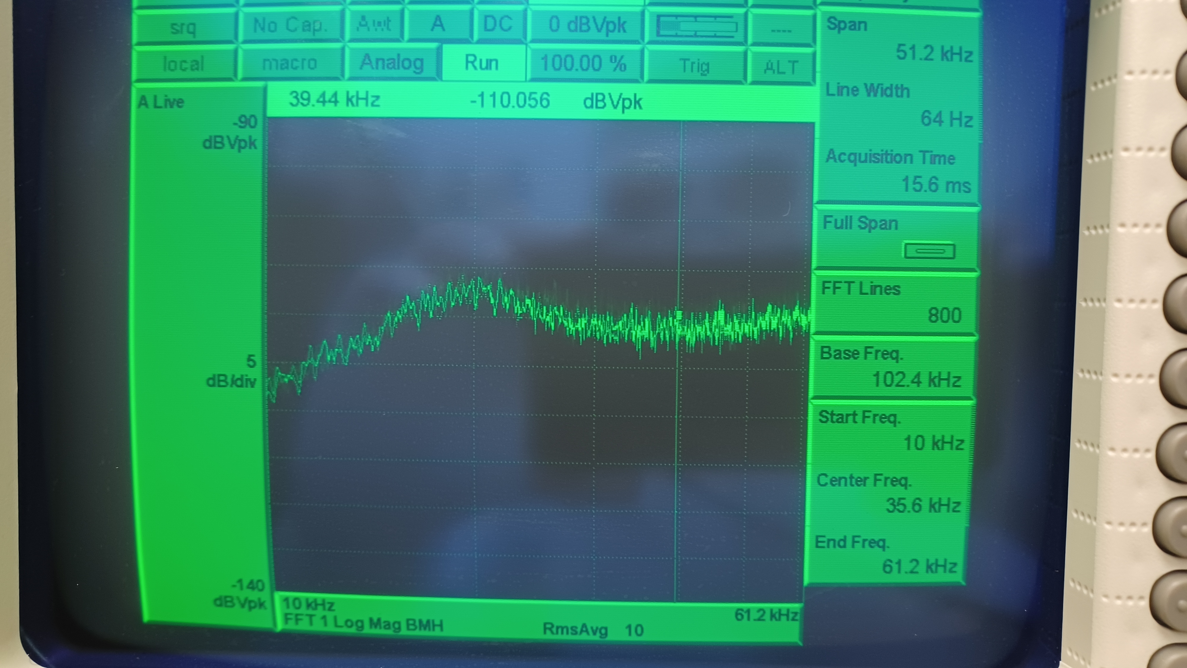
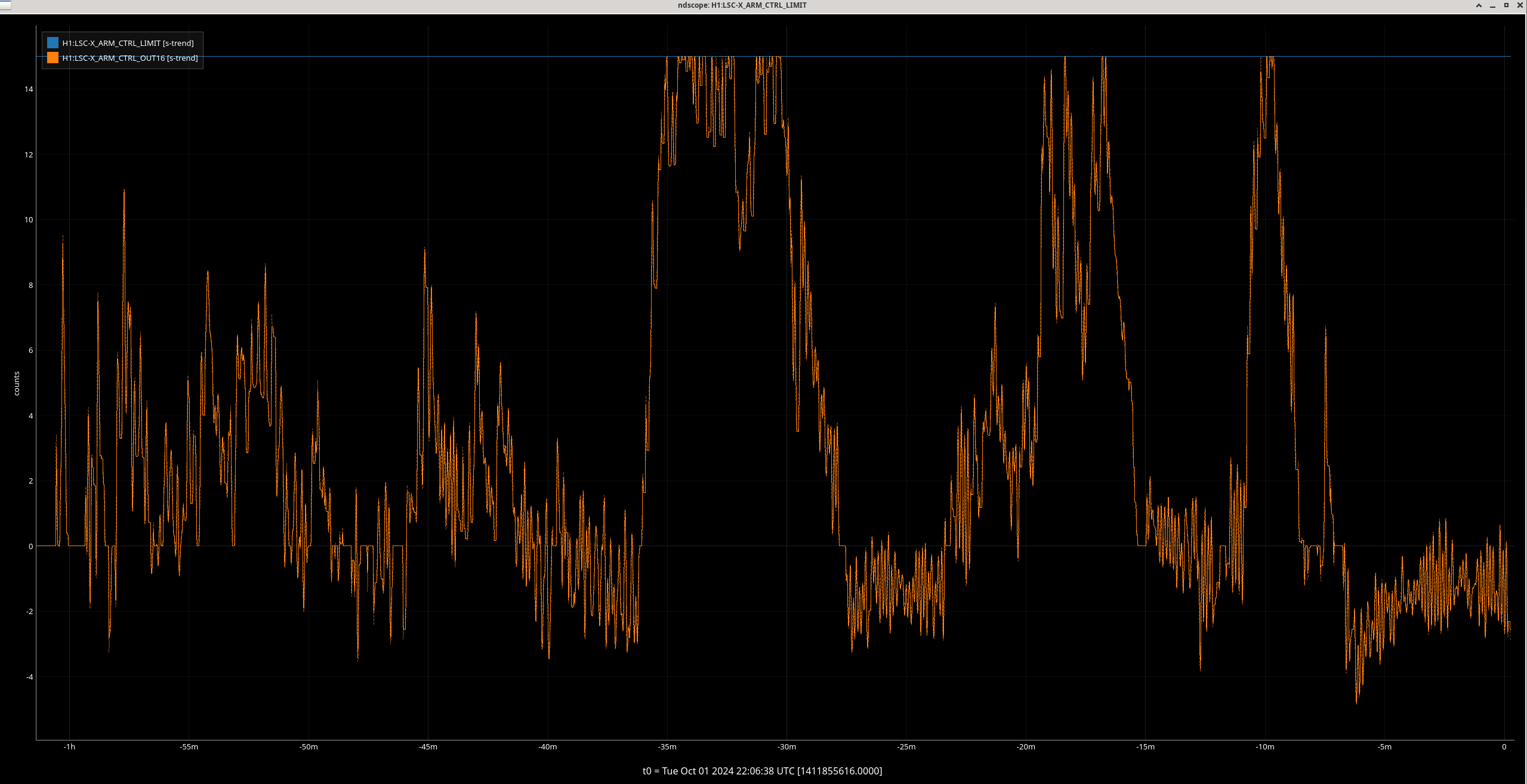
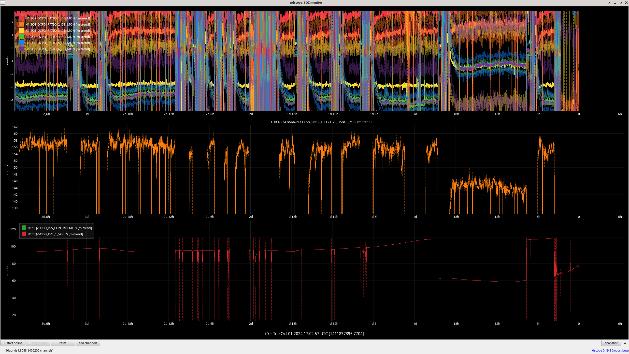
Once the box was installed I took a TF, this time from inside the enclosure using the Agilent unit we keep in there. The TF looked just fine and as expected, see 2nd attachment. With a common gain of 15 and a fast gain of 9 the FSS has a UGF of 452 kHz with 65° of phase margin; the peaks around 770 kHz are still present like normal. We decided to check the crossover (where the NPRO PZT and the phase-correcting EOM meet) at ~20 kHz (this is set with the fast gain). The 3rd attachment shows the crossover as found, with a fast gain of 9. We tried raising the fast gain, but this made the crossover peak larger. Lowering the fast gain made the peak smaller but also starts to raise the overall signal (see 4th and 5th attachments, with a fast gain of 7 and 6, respectively). We decided to leave the fast gain at 7 for now, will see how things behave (in the 3 hours since we made this change and the time of writing this alog behavior seems unchanged). The picture with the fast gain at 7 does looke a little worse than the intial one with fast gain at 9; not sure why, we went back and forth between them a couple times and 9 looked worse than 7 each time (maybe I got "lucky" with the camera shot?). This done we transitioned the enclosure back to Science Mode.
Before leaving the LVEA we tried one more thing. Since we had a successful TF measurement inside the enclosure, we hooked up the Agilent unit by the PSL/ISC racks again and took a TF (since I had an apparent junk measurement with this same unit earlier in the day, see that 1st attachment again). The TF looked perfectly fine, matched the measurement done inside the enclosure. Not sure where the garbage TF from this morning came from, at this point I can only call it "user error of unknown origin."
So we've ended where we started, sure there's a problem but not sure where it is. The current TTFSS appears to be operating correctly, but the FAST signal is still glitching; we even saw glitching with the IMC unlocked, although Ryan reports that it "seems" like the glitching is more frequent when the IMC is locked (maybe IFO feedback is exacerbating an existing issue...). Marc and Fil have been testing a newer gen of TTFSS (not the same as used in SQZ, as that one is not compatible with the PSL as currently wired), so once that is qualified we will try switching to it (Peter King had it working with the RefCav in the optics lab, so it should work with the PSL). We'll try that next.


