Ansel Neunzert, Evan Goetz, Owen (Zhiyu) Zhang
Summary
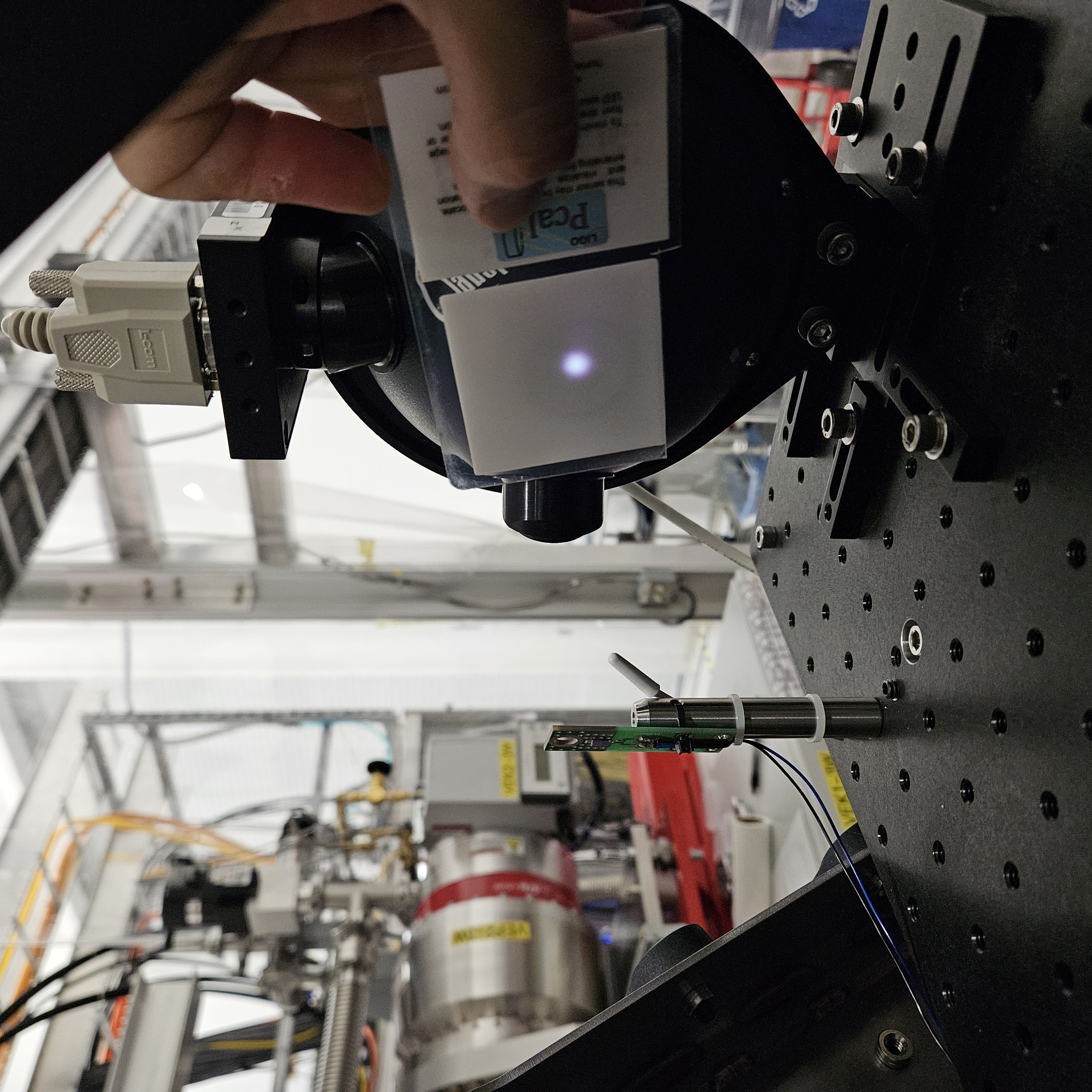
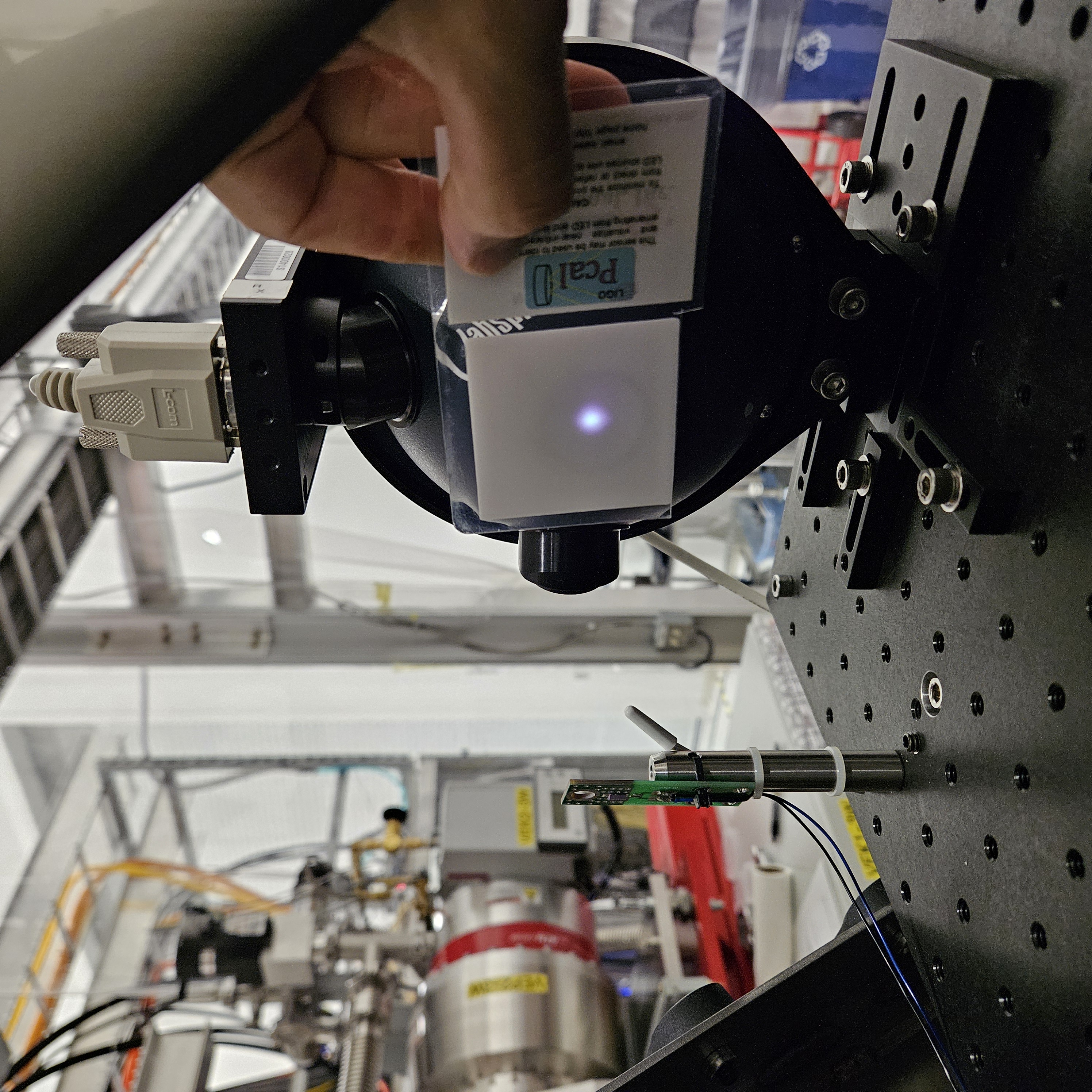
Following the PSL control box 1 move to a separate power supply (see LHO aLOG 79593), we search the recent Fscan spectra for any evidence of the 9.5 Hz comb triplet artifacts. The configuration change seems promising. There is strong evidence that this change has had a positive effect. However, there are a few important caveats to keep in mind.
Q: Does the comb improve in DARM?
A: Yes. However, it has changed/improved before (and later reversed the change), so this is not conclusive by itself.
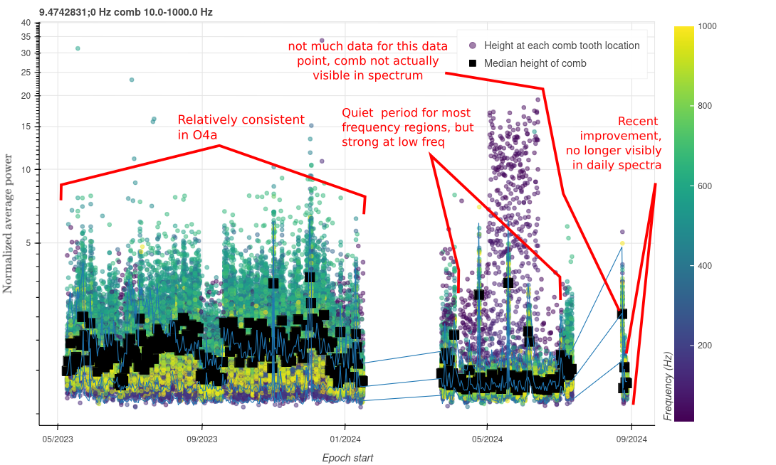
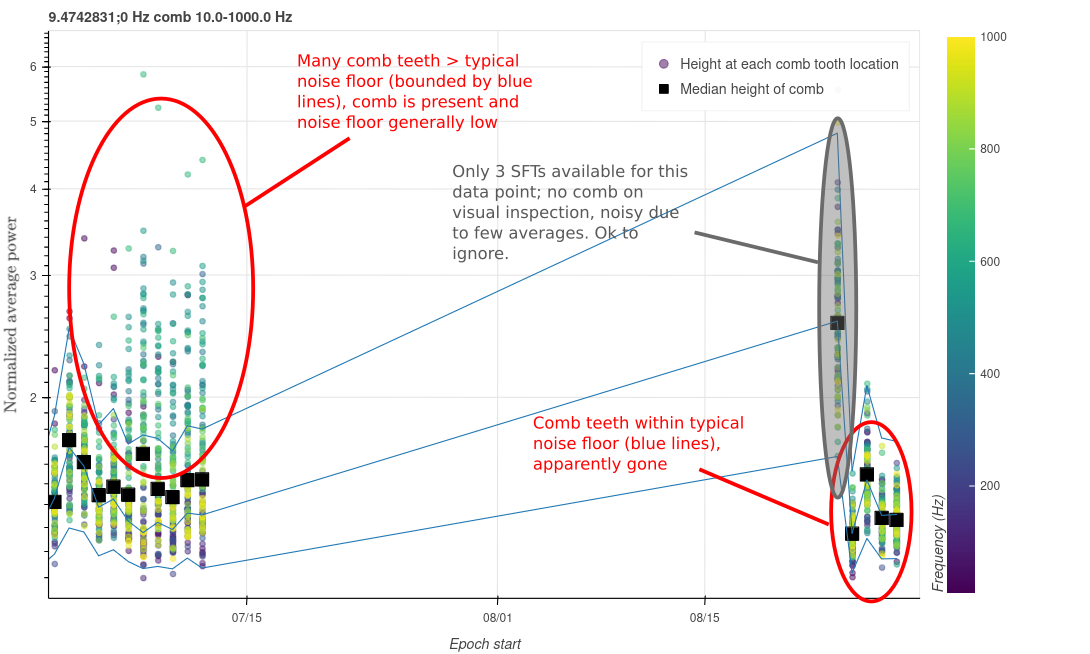
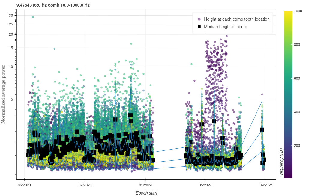
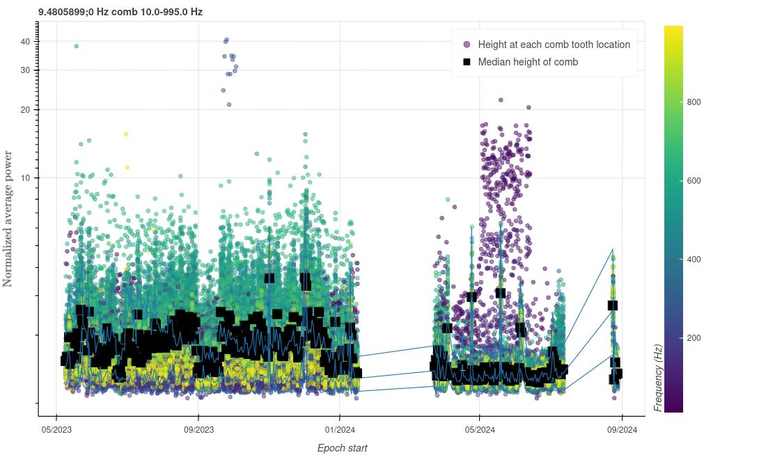
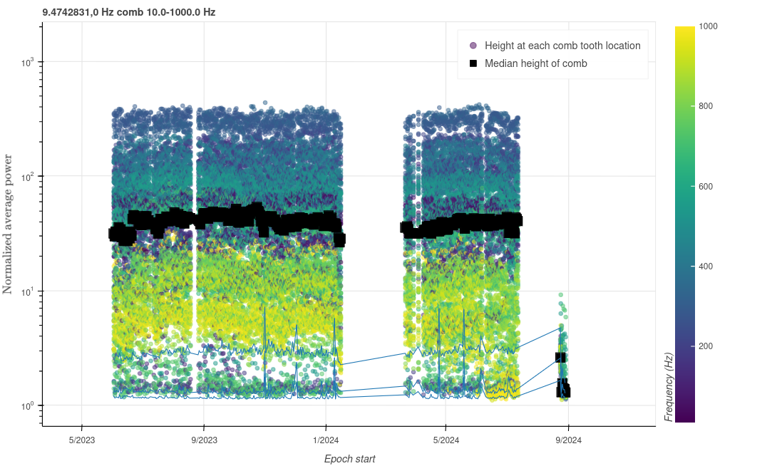
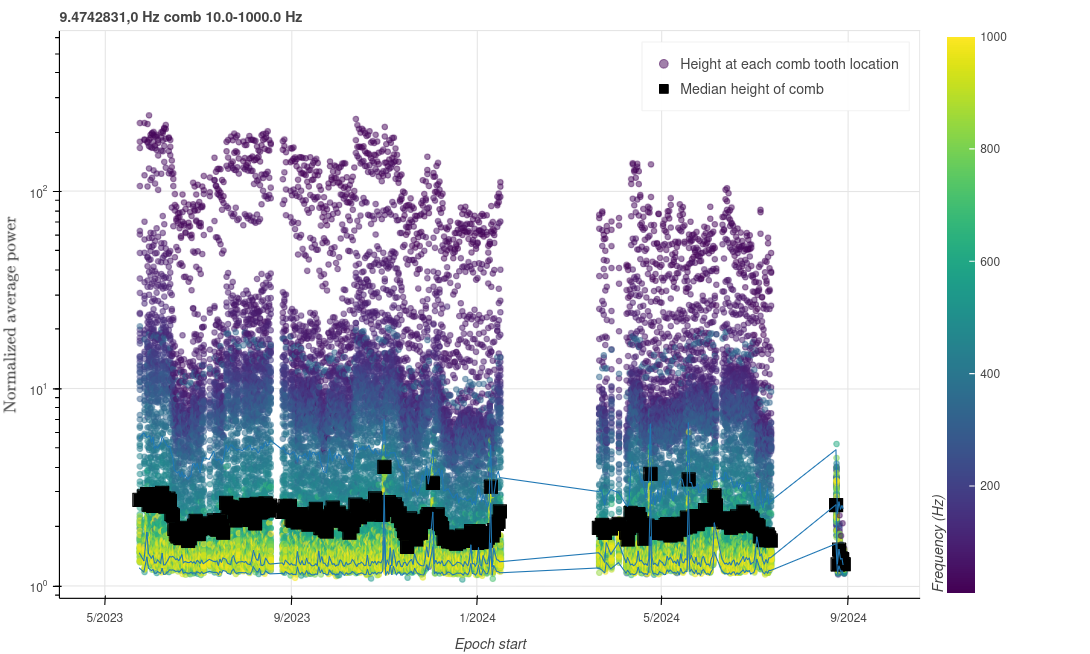
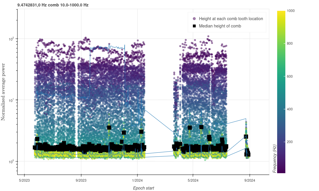
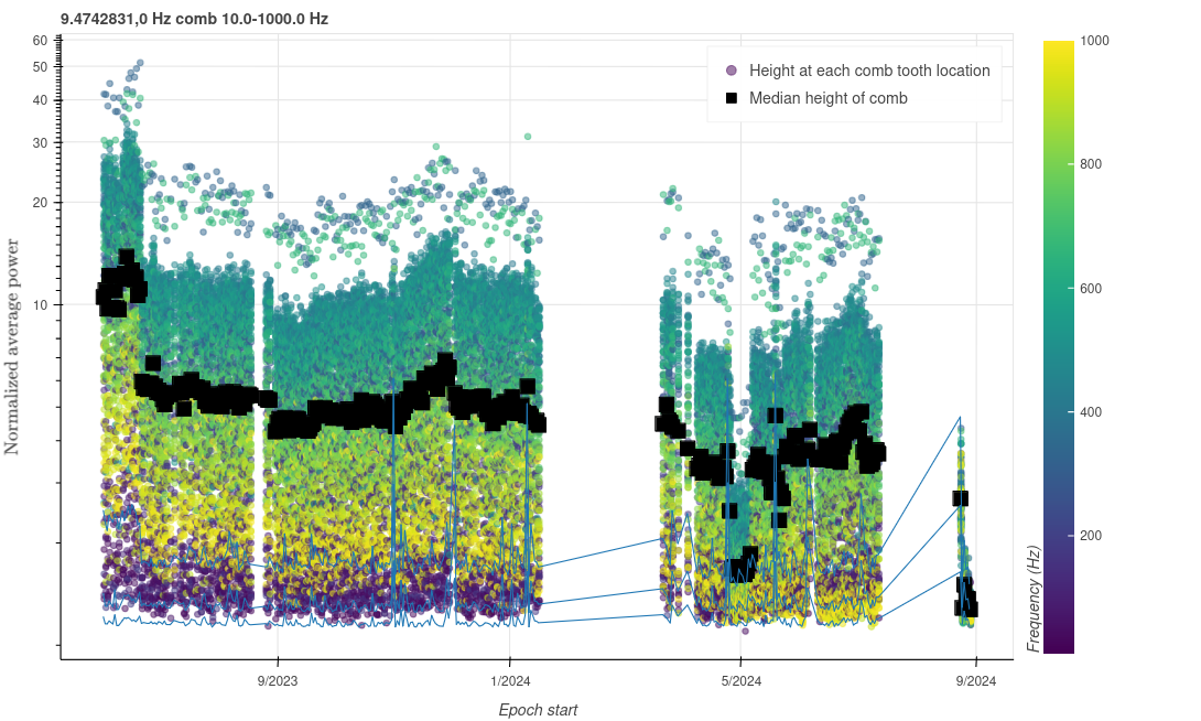
Figures 1-4 show the behavior of the comb in DARM over O4 so far. Figures 1 and 2 are annotated with key interpretations, and Figure 2 is a zoom of Figure 1. Note that the data points are actually the maximum values within a narrow spectral region (+/- 0.11 Hz, 20 spectral bins) around the expected comb peak positions. This is necessary because the exact frequency of the comb shifts unpredictably, and for high-frequency peaks this shift has a larger effect.
Based on these figures, there was a period in O4b when the comb’s behavior changed considerably, and it was essentially not visible at high frequencies in daily spectra. However, it was stronger at low frequencies (below 100 Hz) during this time. This is not understood, and in fact has not been noted before. Maybe the coupling changed? In any case, it came back to a more typical form in late July. So, we should be aware that an apparent improvement is not conclusive evidence that it won’t change again.
However, the recent change seems qualitatively different. We do not see evidence of low or high frequency peaks in recent days. This is good news.
Q: Does the comb improve in known witness channels?
A: Yes, and the improvement is more obvious here, including in channels where the comb has previously been steady throughout O4. This is cause for optimism, again with some caveats.
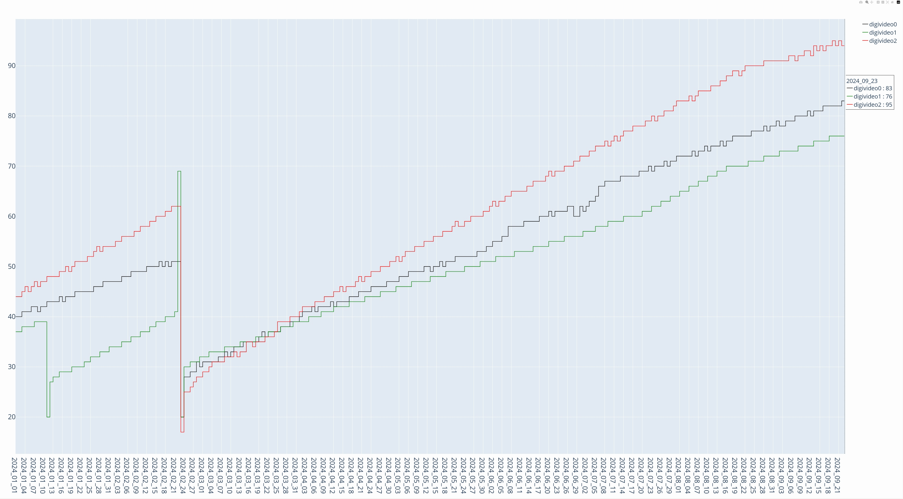
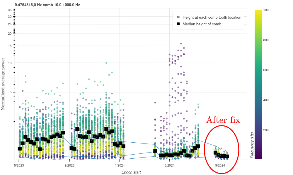
To clarify the situation, I made similar history plots (Figures 5-8) for a selection of channels that were previously identified as good witnesses for the comb. (These witness channels were initially identified using coherence data, but I’m plotting normalized average power here for the history tracks. We’re limited here to using channels that are already being tracked by Fscans.)
The improvement is more obvious here, because these channels don’t show the kind of previous long-term variation that we see in the strain data. I looked at two CS magnetometer channels, IMC-F_OUT_DQ, and LSC-MICH_IN1. In all cases, there’s a much more consistent behavior before the power supply isolation, which makes the improvement that much more convincing.
Q: Is it completely gone in all known witness channels?
A: No, there are some hints of it remaining.
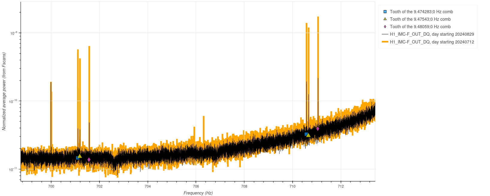
Despite the dramatic improvements, there is subtle evidence of the comb remaining in some places. In particular, as shown in Figure 9, you can still see it at certain high frequencies in the IMC-F_OUT channel. It’s much improved from where it was before, but not entirely gone.

