This morning we changed the demod phase of the POP 9 sensor. The overall summary is that this has a very similar impact to adding a PRCL offset, reducing the PRCL to REFL RIN coupling, and slightly increaing power in the PRC, but not changing the coupling of PRCL noise to DARM. I've turned off the offset, added a new phasing, and updated the PRCL to SRCL subtraction in the LSC input matrix.
More details:
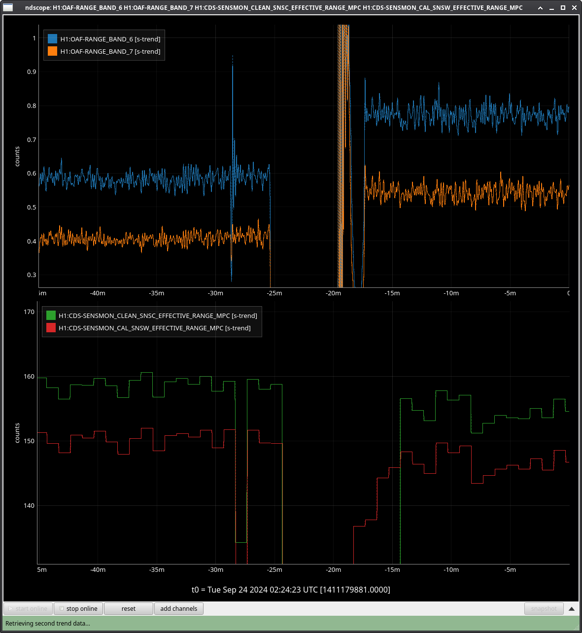
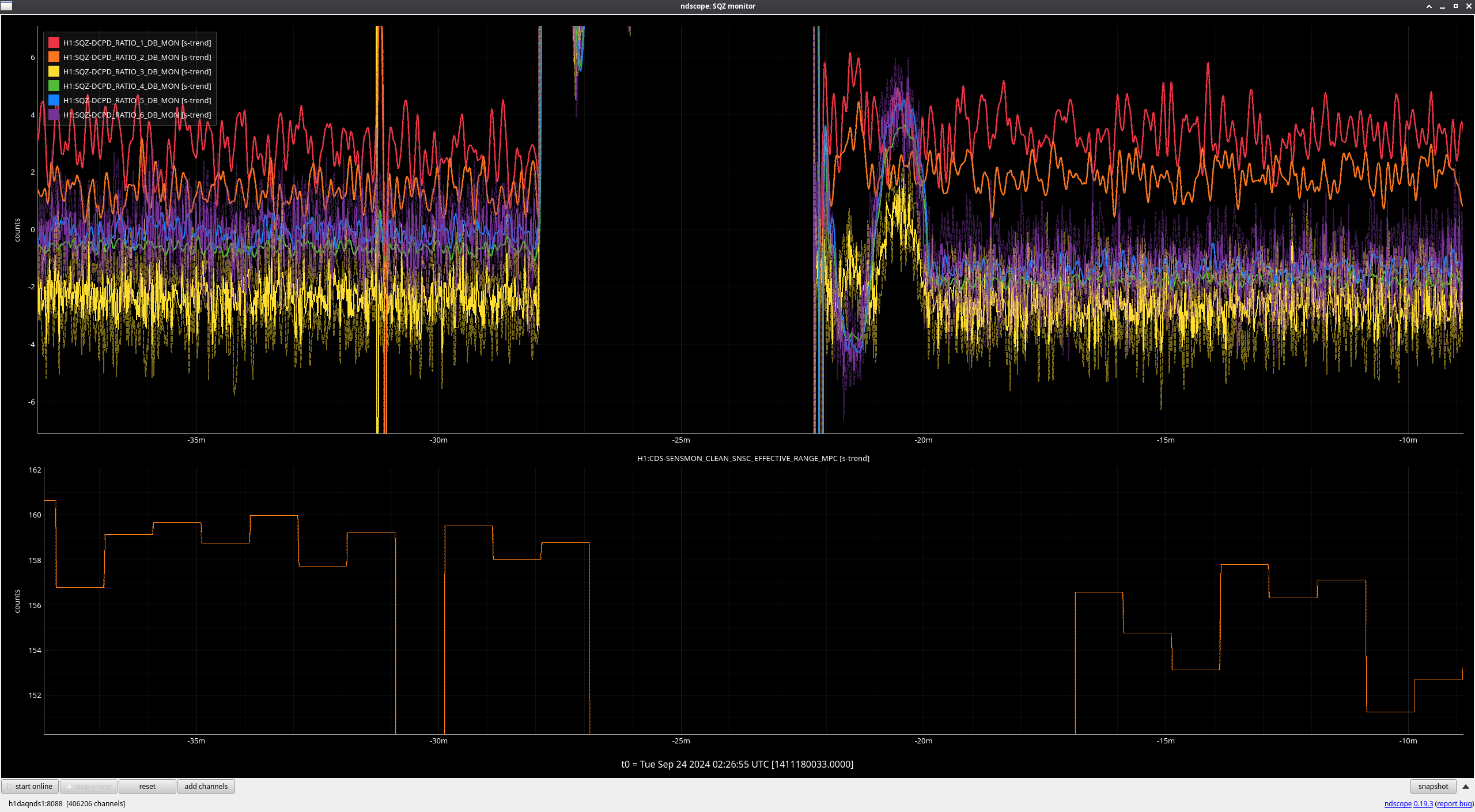
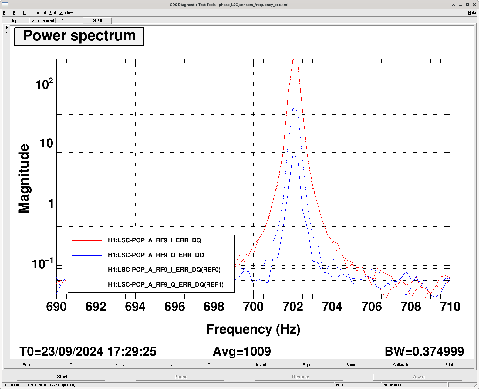
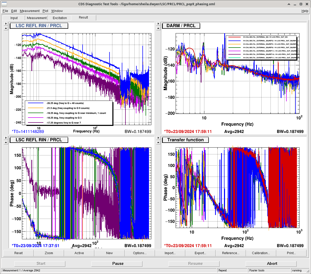
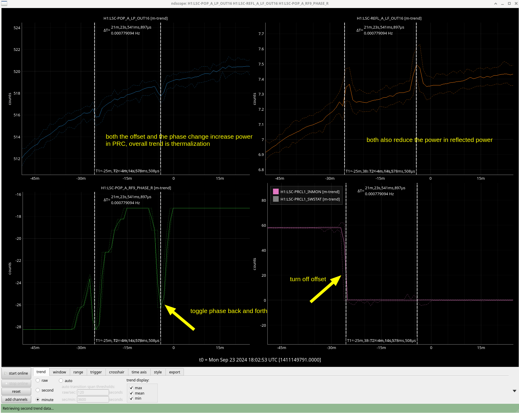
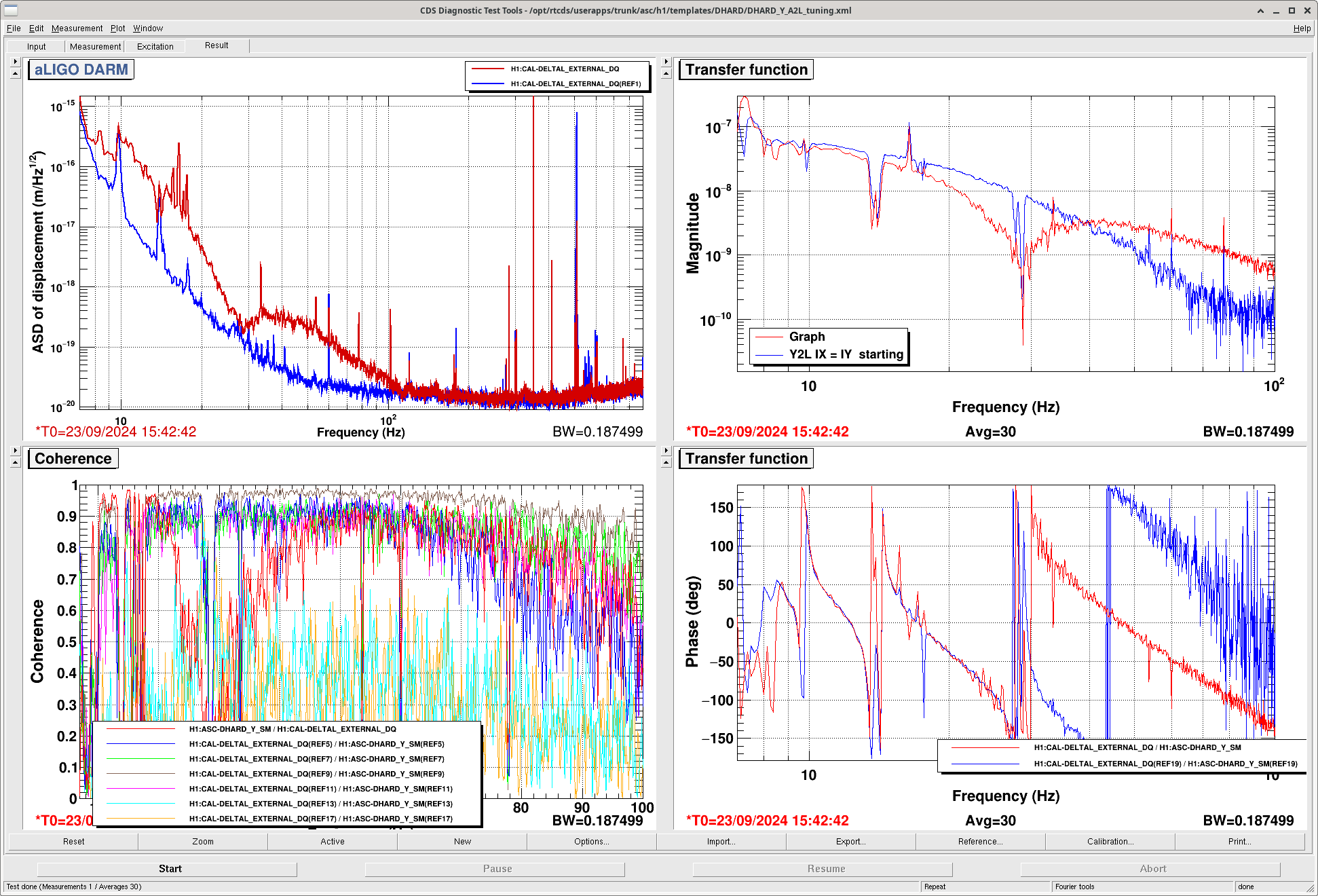
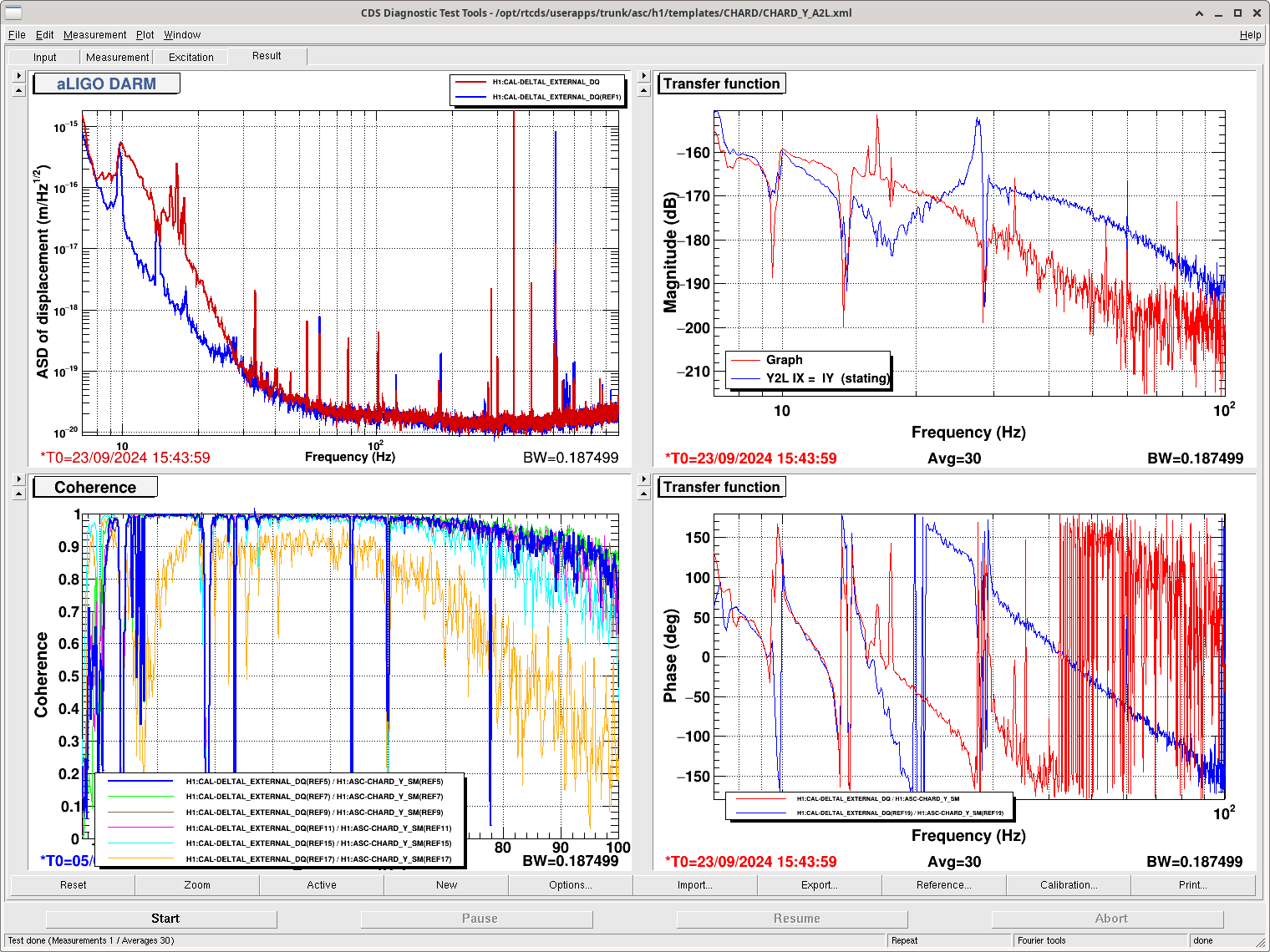
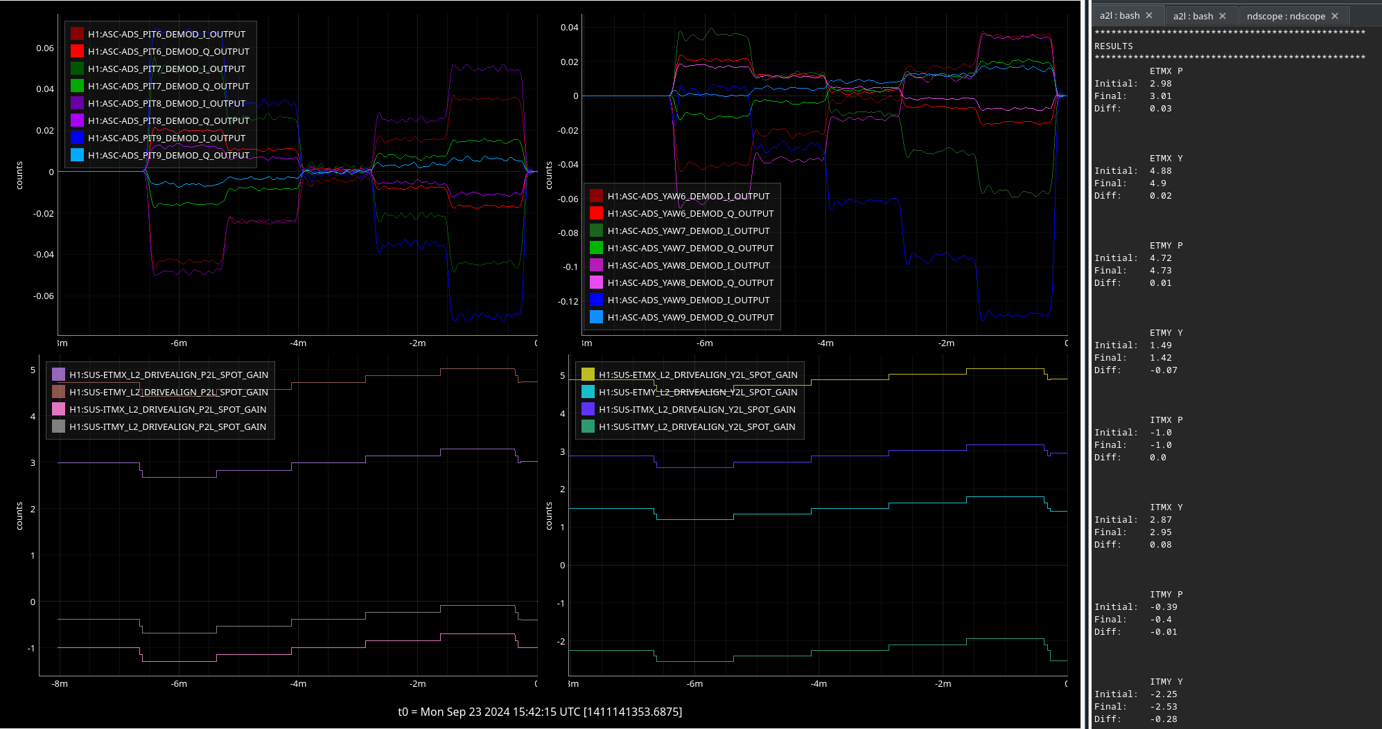
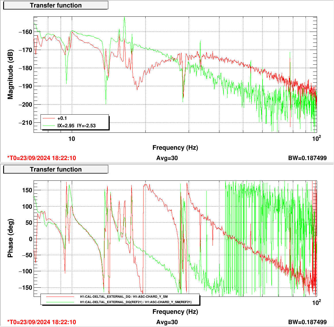
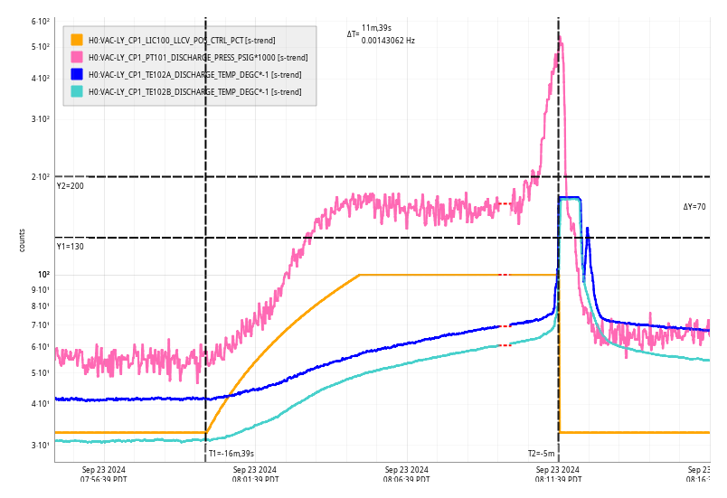
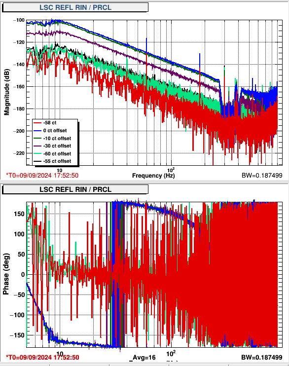
I used a 702.1 Hz frequency noise injection, (template found in userapps/lsc/h1/templates/phase_LSC_sensors_frequency_exc.xml) and adjusted the POP9 phase to reduce the appearance of the frequency injection in Q (screenshot shows initial to final settings change in Q peak). I used Elenna's template to make a PRCL injection and measure the coupling to RELF RIN and DARM during this move, see screenshot. Adjusting the phase reduced the PRCL to REFL RIN coupling in a way that's similar to what Elenna has seen by adjusting the PRCL offset (see 79989 for example). Also similar to what Elenna has seen with the PRCL offset, this has very little impact on the PRCL to DARM coupling. The ndscope screenshot shows how this impacted REFL and POP powers, you can compare the time when I turned off the offset to the time when I tried reverting the phase to the original setting after finding the new setting, the two things have a simlar impact on the reflected power and the power in the PRC.
One interesting observation is that the phase that minimized the PRCL to REFL RIN coupling (as shown by the sign flip in the transfer function), is different from the phase that minimzed the frequency injection coupling to POP 9Q, by 2 degrees. I've left this at the phase that minimizes REFL RIN coupling. The impact on the power build ups is small enough that this two degree difference can't be evaluated using them.
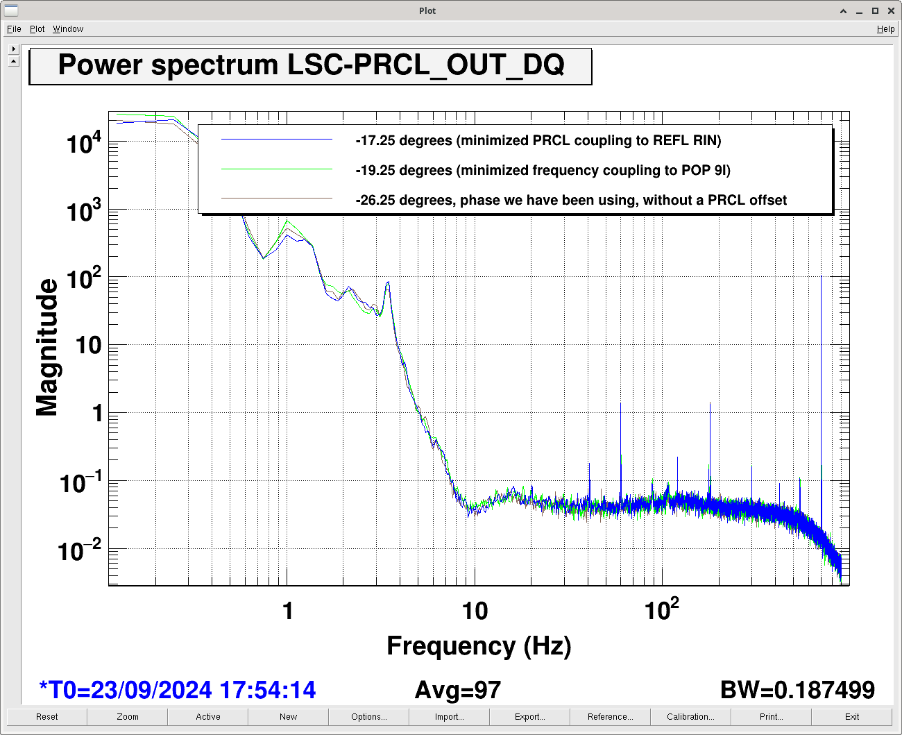
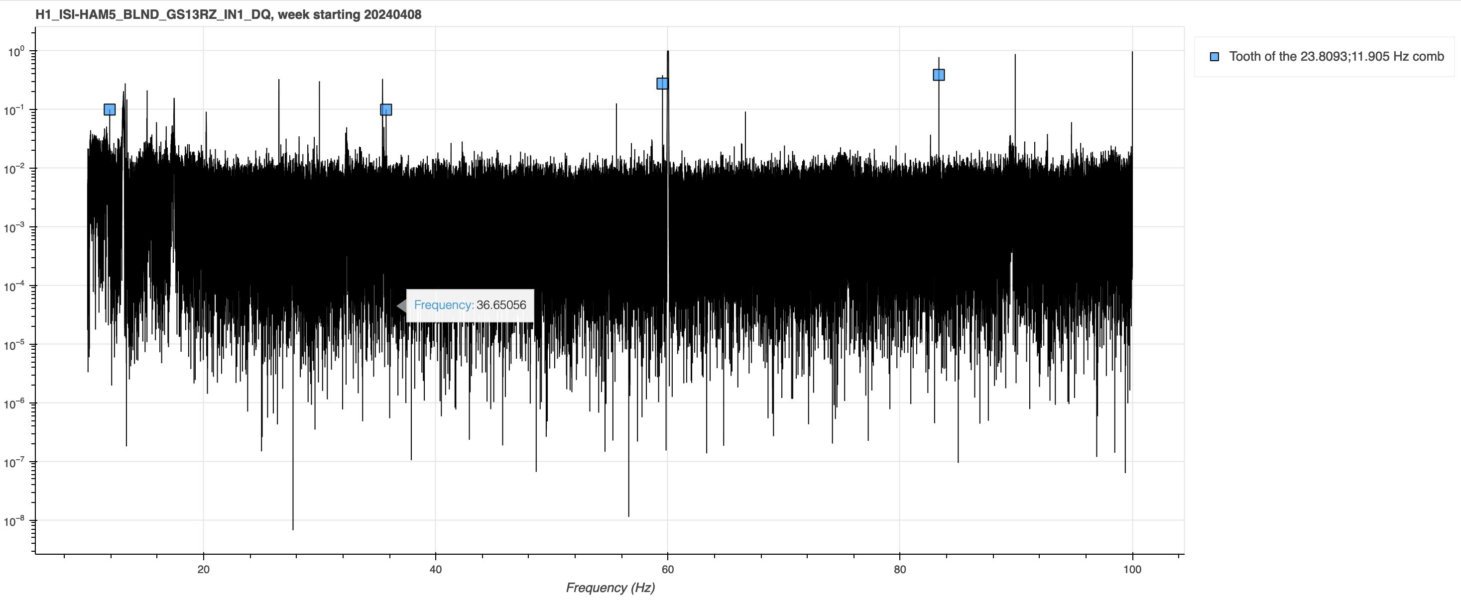
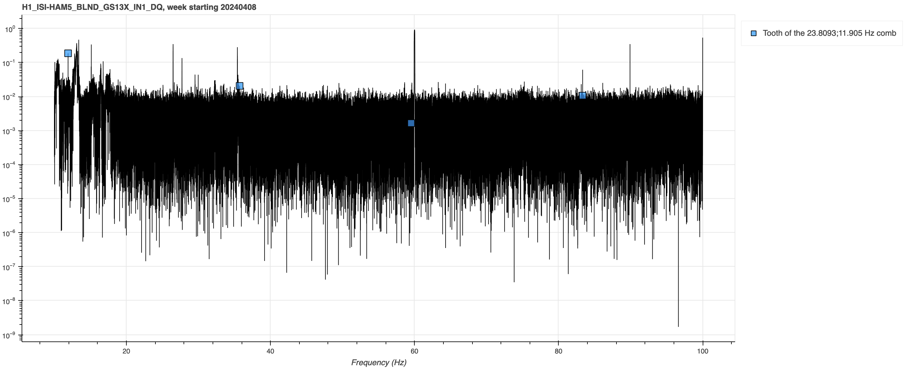
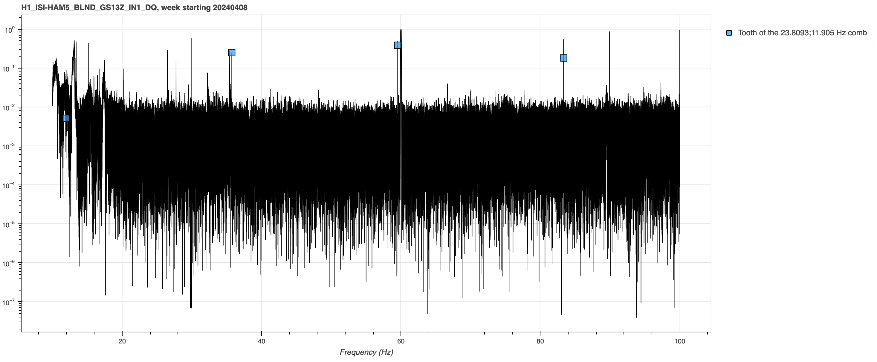
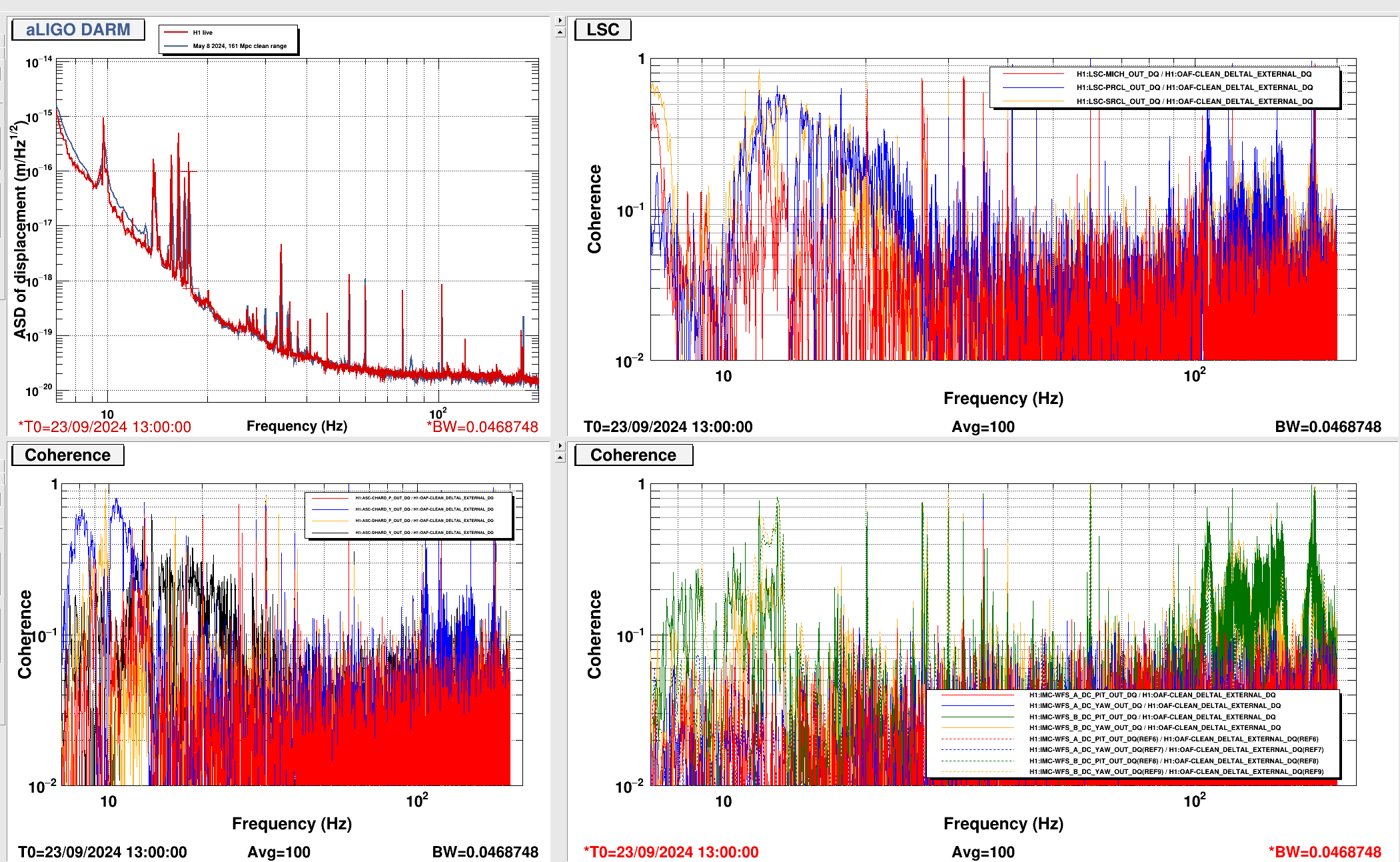
Another observation is that the change in phasing doesn't seem to have an impact on the PRCL spectrum, spectrum screenshot.
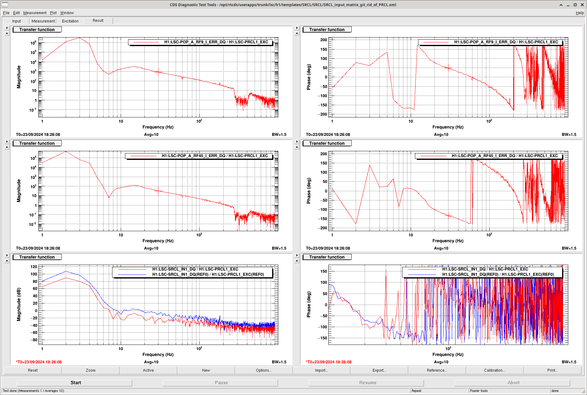
Lastly, I did another PRCL excitation to measure the coupling to POP 45 and POP9 I, using the template in userapps/lsc/h1/templates/SRCL/SRCL/SRCL_input_matrix_git_rid_of_PRCL.xml (excuse the typo). I used this measurment to try to zero the PRCL coupling to SRCL ((POP45/PRCL)*MTRX_5_3 + (POP9I/PRCL)*MTRX_5_1 = 0, and found that this matrix element needed to be updated from 0.1185 to 0.1408. This was last updated by Jenne Driggers in 70919. The update reduced the SRCL to PRCL coupling by about 20dB, shown here.
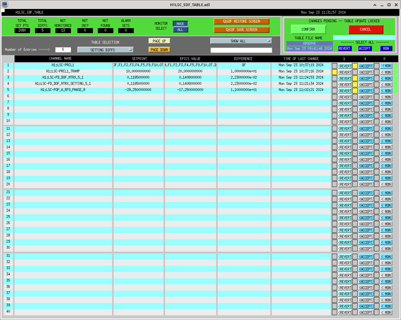
Lastly we edited the guardian to not use the PRCL offset, and update the PRCL to SRCL input matrix element, and accepted the new matrix and phasing in SDF (in the observe file, and now also in the safe file).