david.barker@LIGO.ORG - posted 08:26, Friday 20 September 2024 (80207)
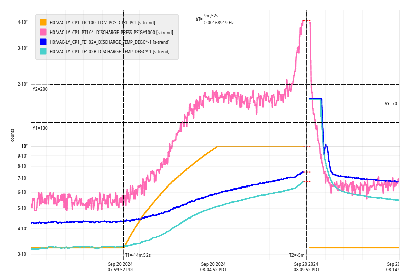
Fri CP1 Fill
Fri Sep 20 08:09:52 2024 INFO: Fill completed in 9min 48secs
Images attached to this report
Fri Sep 20 08:09:52 2024 INFO: Fill completed in 9min 48secs
Closes FAMIS26298
Laser Status:
NPRO output power is 1.824W (nominal ~2W)
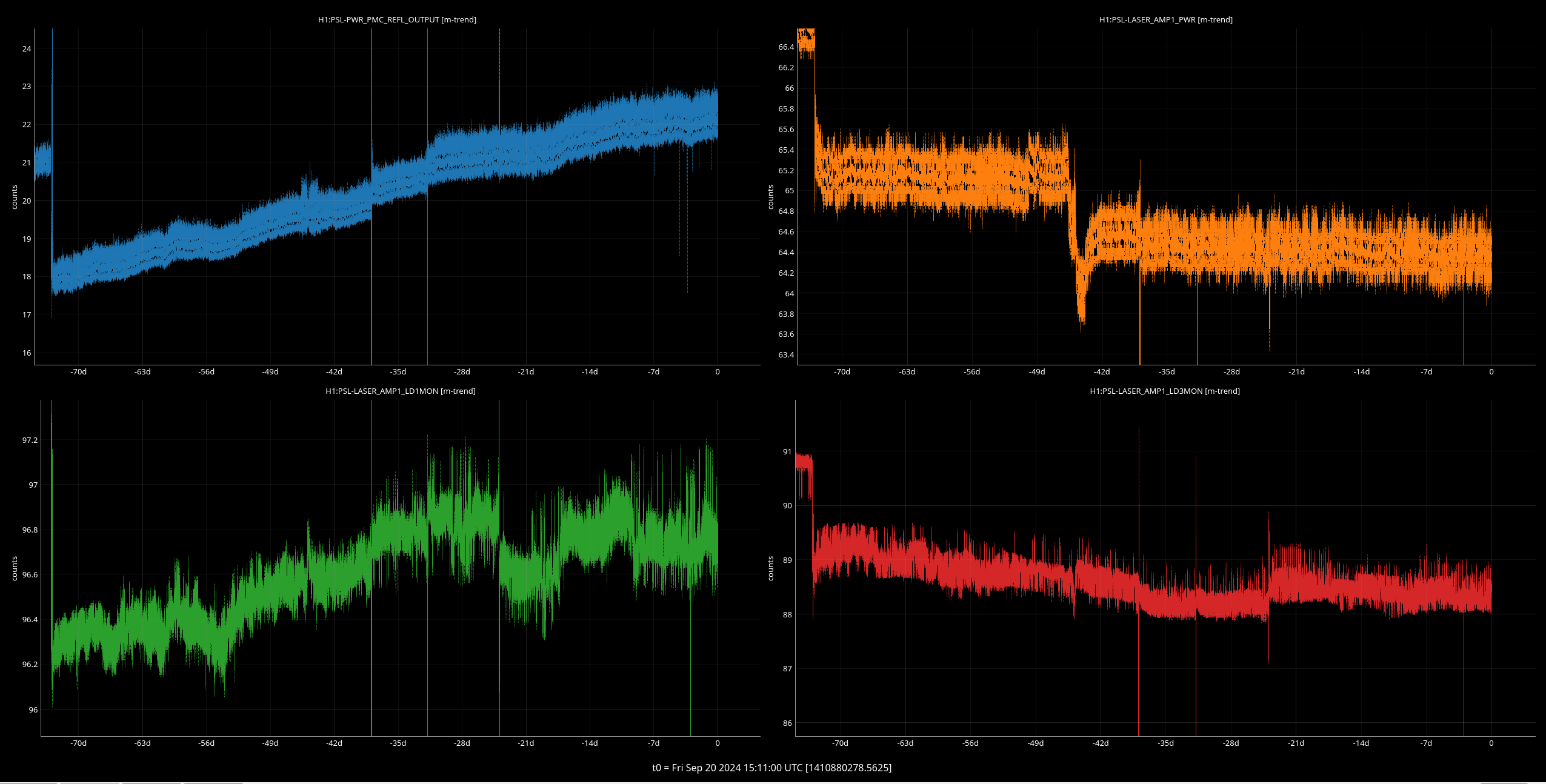
AMP1 output power is 64.37W (nominal ~70W)
AMP2 output power is 137.4W (nominal 135-140W)
NPRO watchdog is GREEN
AMP1 watchdog is GREEN
AMP2 watchdog is GREEN
PDWD watchdog is GREEN
PMC:
It has been locked 23 days, 21 hr 37 minutes
Reflected power = 22.08W
Transmitted power = 104.2W
PowerSum = 126.3W
FSS:
It has been locked for 0 days 11 hr and 13 min
TPD[V] = 0.804V
ISS:
The diffracted power is around 2.2%
Last saturation event was 0 days 11 hours and 13 minutes ago
Possible Issues:
AMP1 power is low, there was a step down about 47 days ago.
PMC reflected power is high, it appears to have been rising for the past >2 months.
TITLE: 09/20 Day Shift: 1430-2330 UTC (0730-1630 PST), all times posted in UTC
STATE of H1: Observing at 150Mpc
OUTGOING OPERATOR: Oli
CURRENT ENVIRONMENT:
SEI_ENV state: CALM
Wind: 10mph Gusts, 6mph 3min avg
Primary useism: 0.02 μm/s
Secondary useism: 0.08 μm/s
QUICK SUMMARY:
We dropped observing from 13:14 to 13:18 UTC this morning, it appears to be from the SQZer loosing lock and relocking itself. The PMC GRD specifically.
TITLE: 09/20 Eve Shift: 2330-0500 UTC (1630-2200 PST), all times posted in UTC
STATE of H1: Observing at 157Mpc
INCOMING OPERATOR: Oli
SHIFT SUMMARY: High winds this evening which possibly contributed to the one lockloss. Relocking was automated and otherwise a quiet shift.
LOG:
No log for this shift.
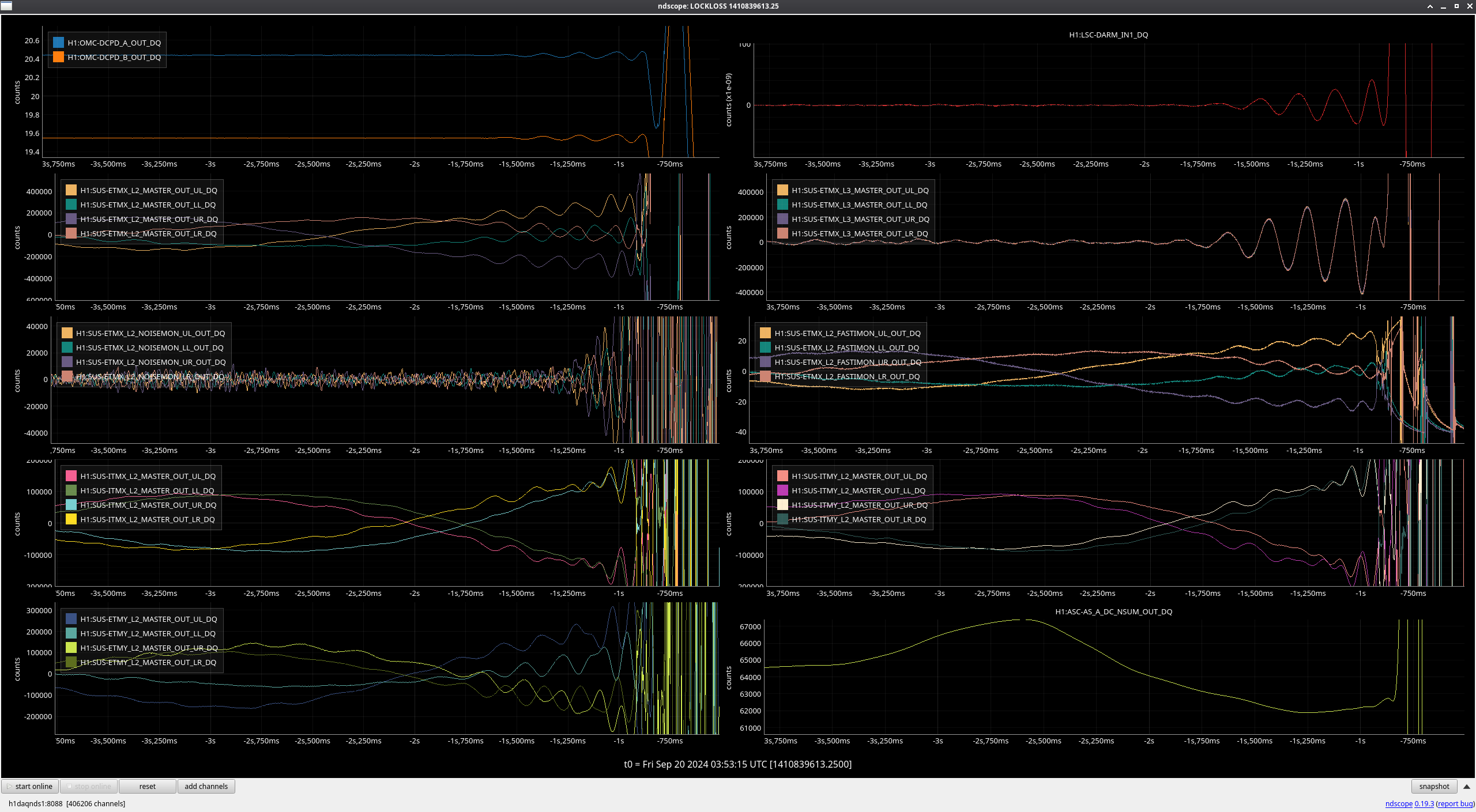
Lockloss @ 03:53 UTC - link to lockloss tool
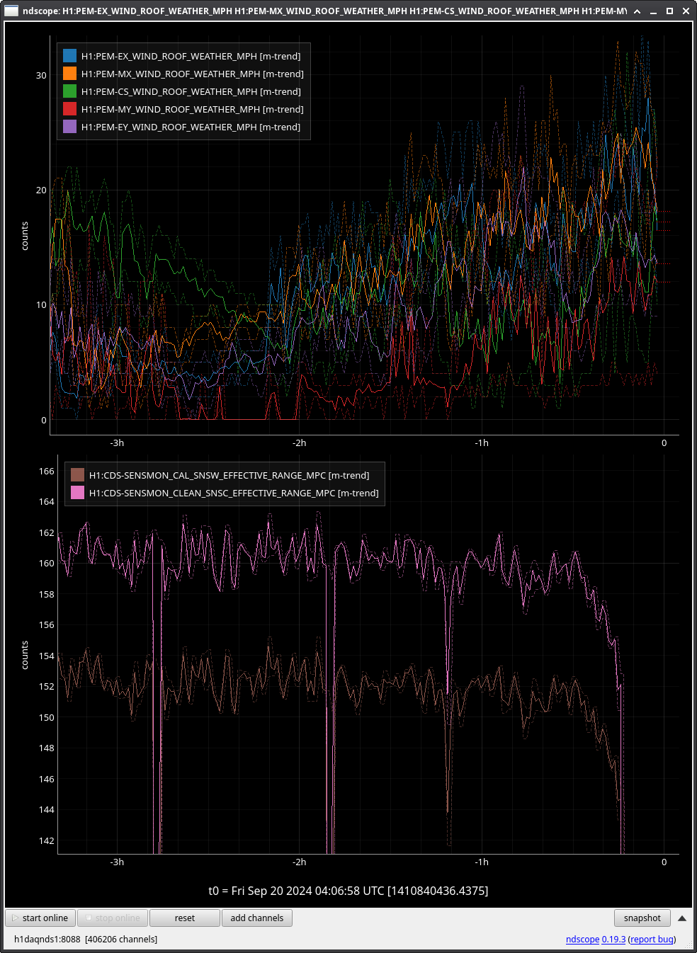
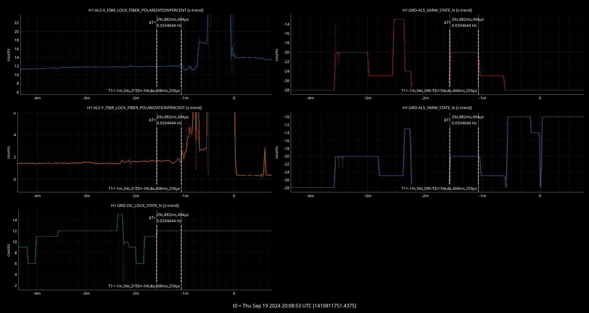
No extremely obvious cause, but seeing as winds have recently gusted up to over 30mph and multiple suspensions seem to have started shaking about a second before the lockloss, my initial assumption is that this was wind-related.
Range had also started dropping for about 30 minutes prior to the lockloss, possibly due to the higher winds? (trend attached)
Back to observing at 04:49 UTC. Fully automated relock without an initial alignment, however many signals are shaky and acquisition took slightly longer due to high winds.
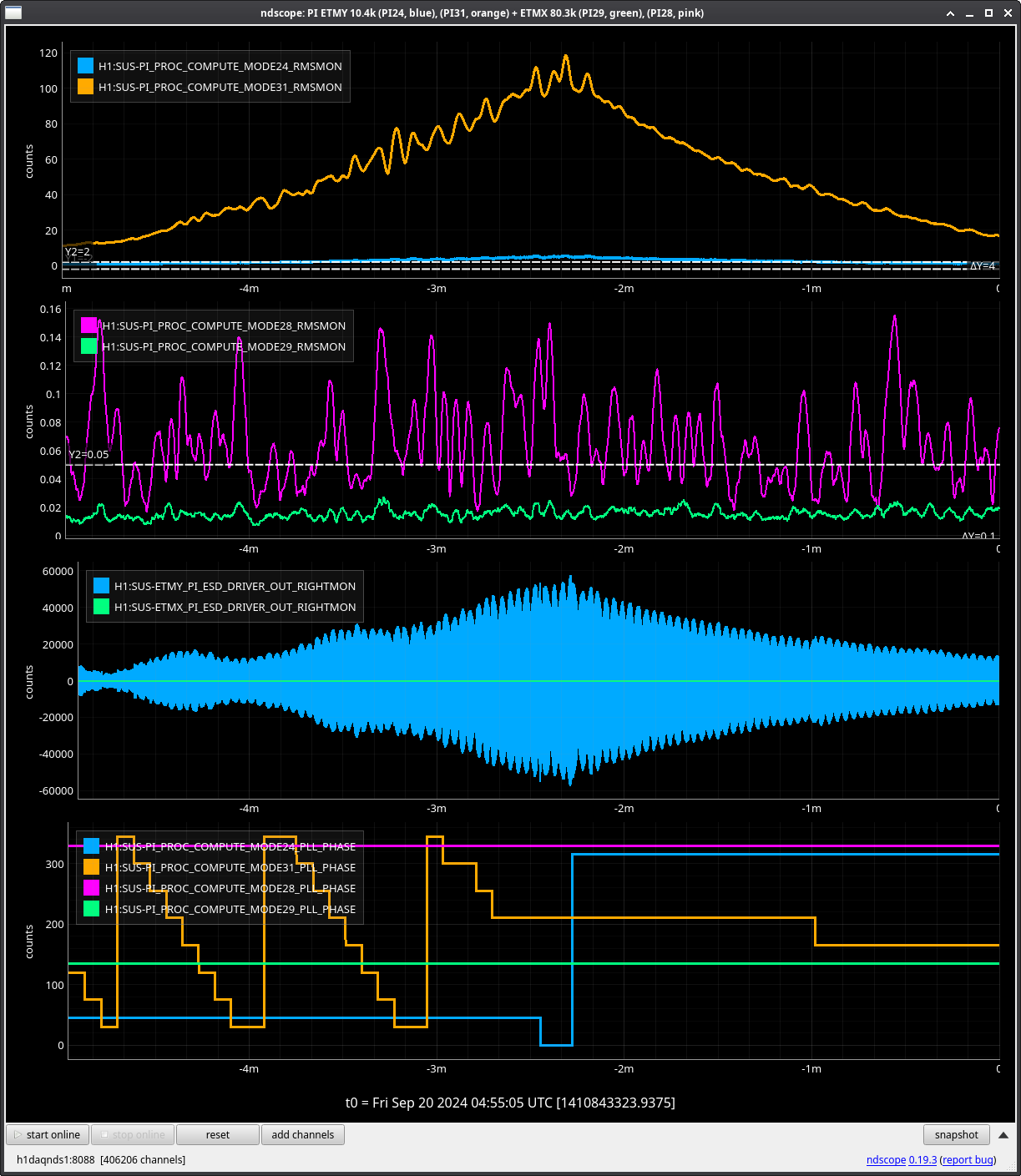
PI mode 31 started ringing up shortly after NLN. Guardian was able to damp it down, but not until mode 24 also started rising and damping started on that mode. Unsure if this is a coincidence or if damping mode 24 is actually what brought down mode 31.
TITLE: 09/19 Day Shift: 1430-2330 UTC (0730-1630 PST), all times posted in UTC
STATE of H1: Observing at 155Mpc
INCOMING OPERATOR: Ryan S
SHIFT SUMMARY: Three lock losses during my shift. Two of them are unknown. All reacquisitions have been fully auto. SR3 oplev sums are low since the SR3 move last week. Plans to fix this next maintenance day.
LOG:
| Start Time | System | Name | Location | Lazer_Haz | Task | Time End |
|---|---|---|---|---|---|---|
| 23:58 | SAF | H1 | LVEA | YES | LVEA is laser HAZARD | 18:24 |
| 15:10 | FAC | Kim | Opt lab | n | Tech clean | 15:11 |
| 16:19 | PEM | Robert | LVEA | yes | Setup injections | 18:43 |
| 18:05 | ISC | Sheila | LVEA | yes | Plug in cable by PSL racks | 18:15 |
| 18:14 | CDS | Fil | MY | n | Part dropoff and fiber testing | 19:15 |
| 23:03 | TCS | TJ | MER | n | Checking TCS chillers | 23:13 |
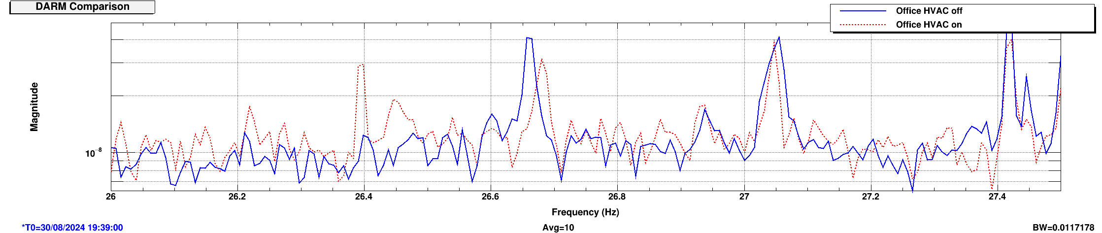
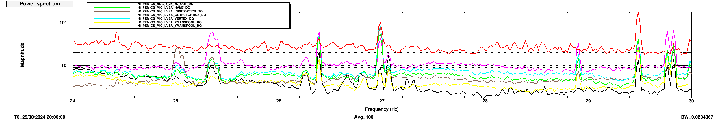
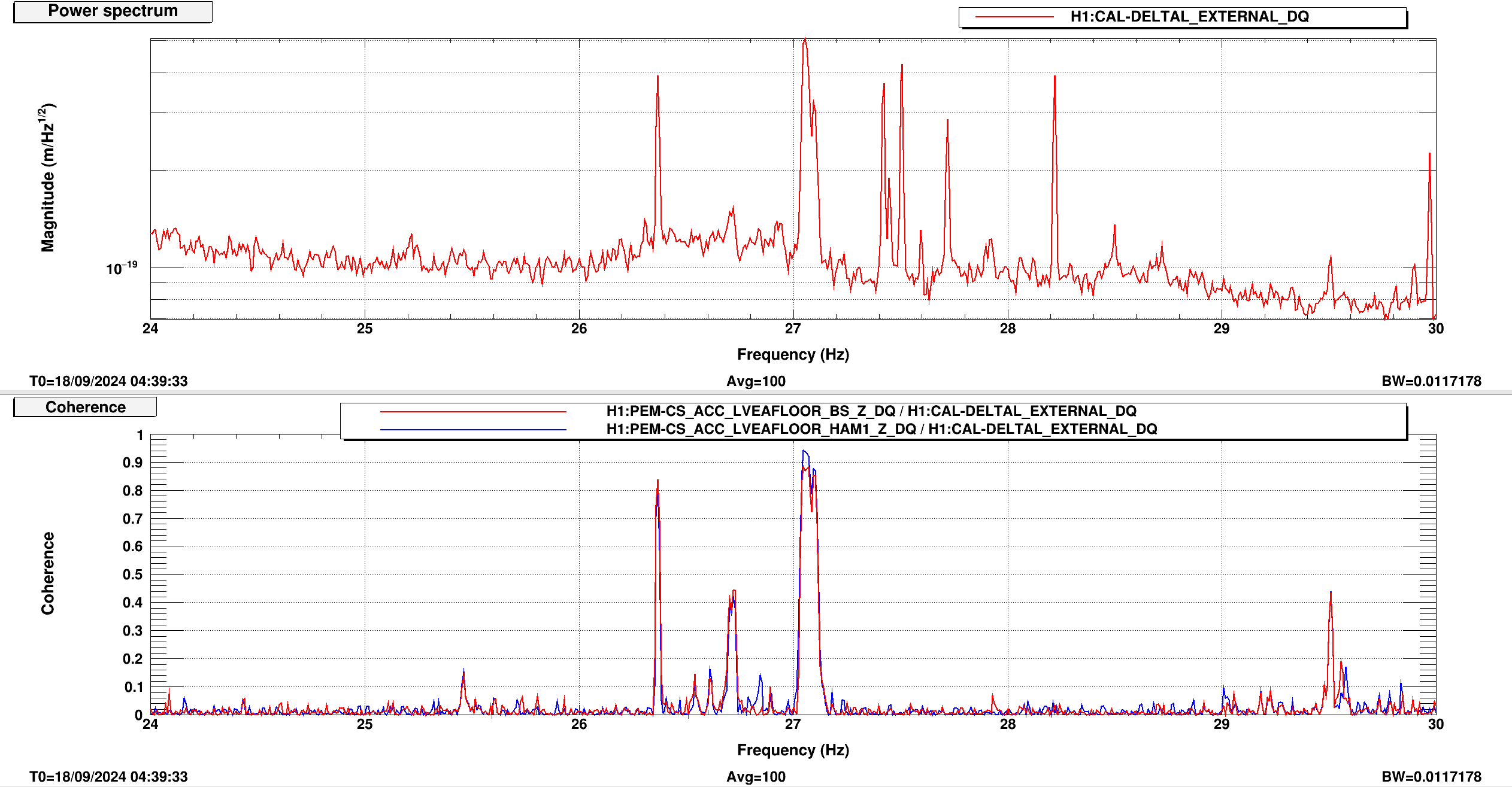
Samantha Callos, Robert Schofield
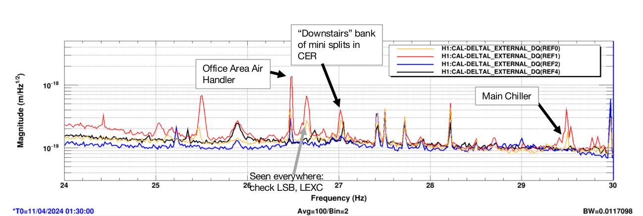
We identified 3 peaks (26.4 Hz, 27 Hz, and 29.5 Hz) in DARM resulting from HVAC systems and the CS Chiller; 1 peak between 26.4 Hz and 27 Hz remains unidentified. See Fig. 1.
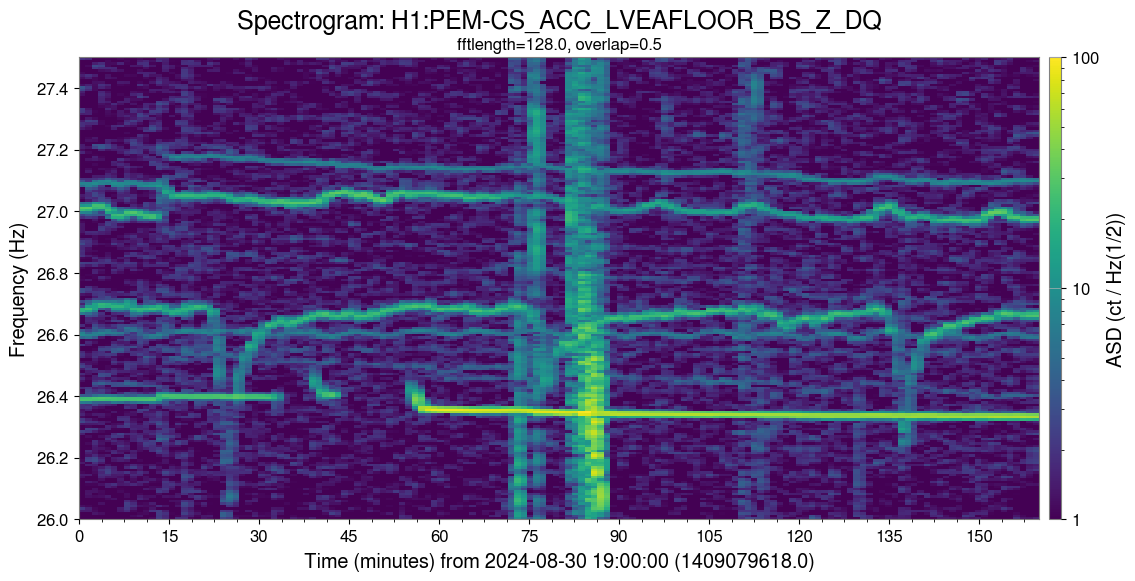
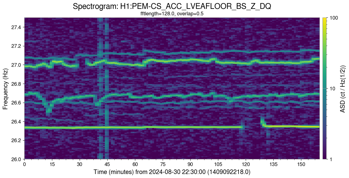
The first peak at 26.4 Hz's source has been found to be the office HVAC system, as shown in Fig. 2. There are two gaps corresponding to when Robert shut down the HVAC system (from alog 79888). Fig. 3 shows the peak at 26.4 Hz disappears in DARM for when the office HVAC is off vs when it is on.
The second peak varies between 26.5 Hz and ~26.7 Hz. It has yet to be identified, but we do know:
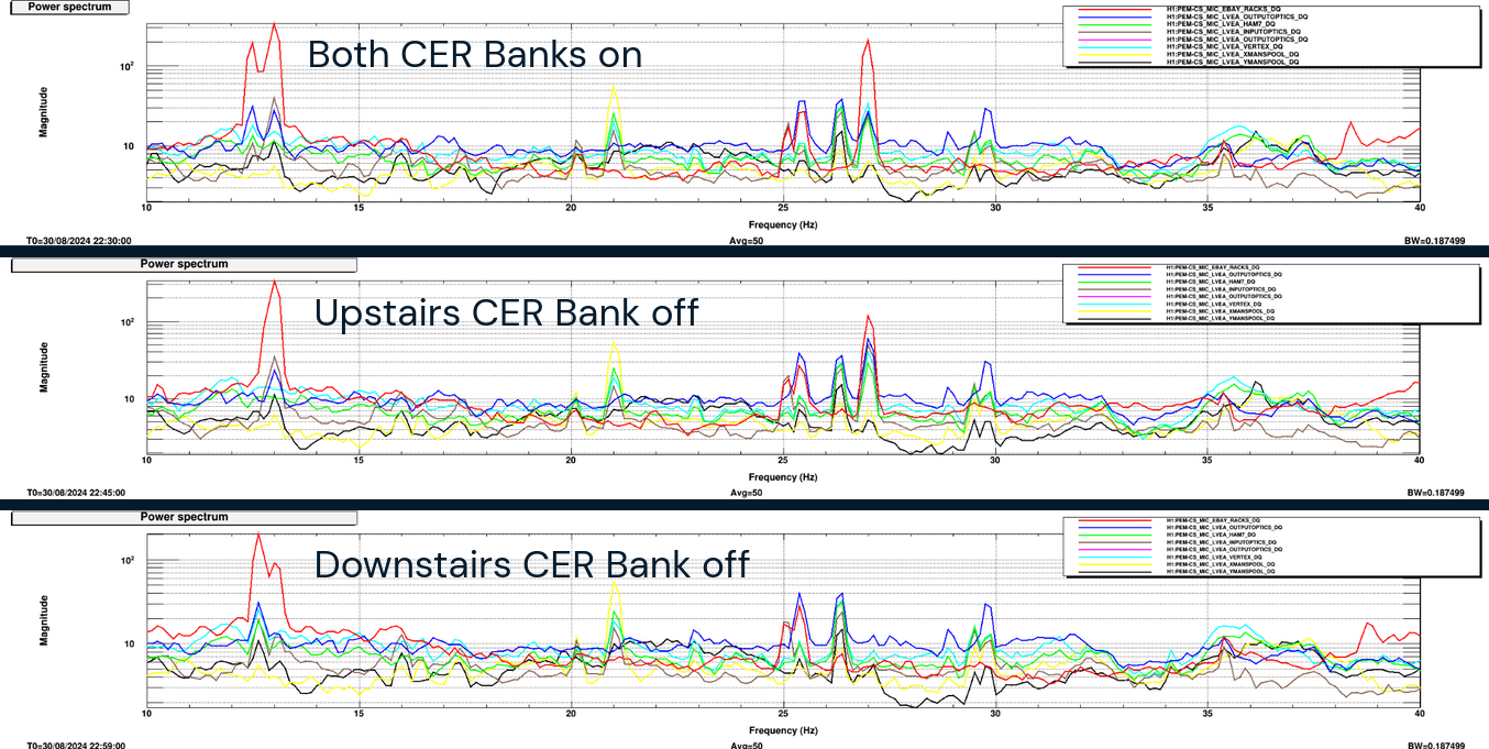
The third (27 Hz) peak's source is the mini splits HVACs controlled by the downstairs thermostat of the CER, as shown in Fig. 4 when the CER HVAC was shut down (alog 80049). It also shows the second round of shut downs of the office HVAC from alog 79888 which reconfirms the first peak. Fig. 5 shows the peak in the mics disappearing when the "downstairs" bank of the mini splits in the CER were turned off.
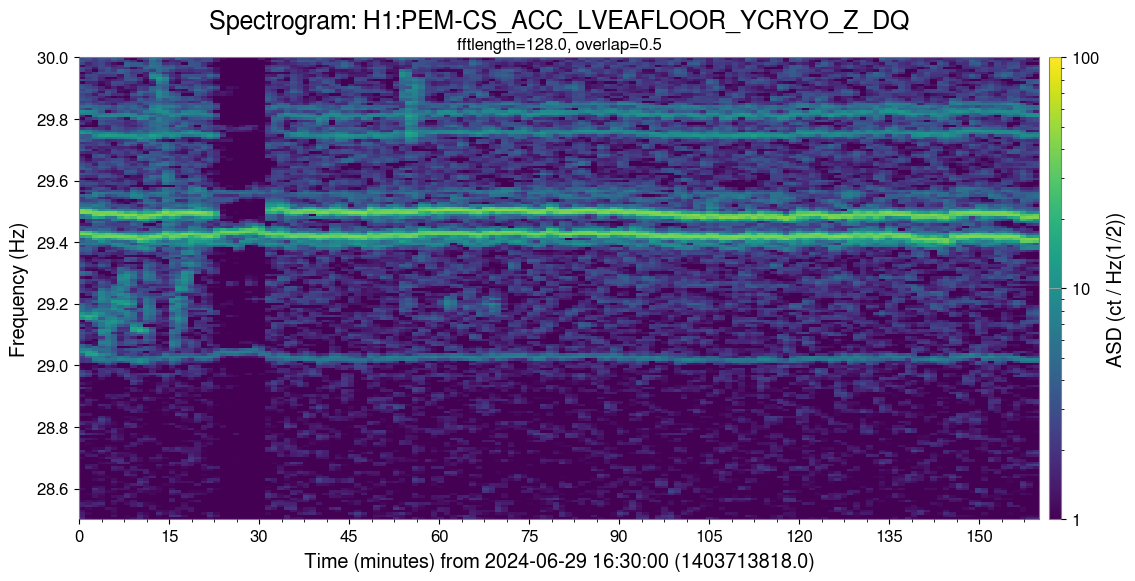
The fourth peak's source is the CS main chiller unit, Fig. 6, at 29.5 Hz. This shut down was done by Robert on June 29th, 2024 (alog 78749). A microphone placed across the road from the chiller pads showed that the 29.5 Hz peak seen in the permanent microphones is much louder near the chillers (see Fig. 7).
Finally, in Fig. 8, the coherence between DARM and floor accelerometers is shown for the peaks mentioned above.
FAMIS27798
I ended up not adding any water to either of the chillers since they both looked near the top of their range. The filters looked good, both the mesh and socks. The dixie cup was dry. Sheet updated.
TITLE: 09/19 Eve Shift: 2330-0500 UTC (1630-2200 PST), all times posted in UTC
STATE of H1: Observing at 156Mpc
OUTGOING OPERATOR: TJ
CURRENT ENVIRONMENT:
SEI_ENV state: CALM
Wind: 14mph Gusts, 9mph 3min avg
Primary useism: 0.02 μm/s
Secondary useism: 0.10 μm/s
QUICK SUMMARY: H1 just made it back to observing minutes before the start of my shift following what sounds like a straightforward reacquisition.
Closes FAMIS 26009
Nothing looks out of the ordinary/weird and measurements are comprable to the last weekly check done (alog 80081)
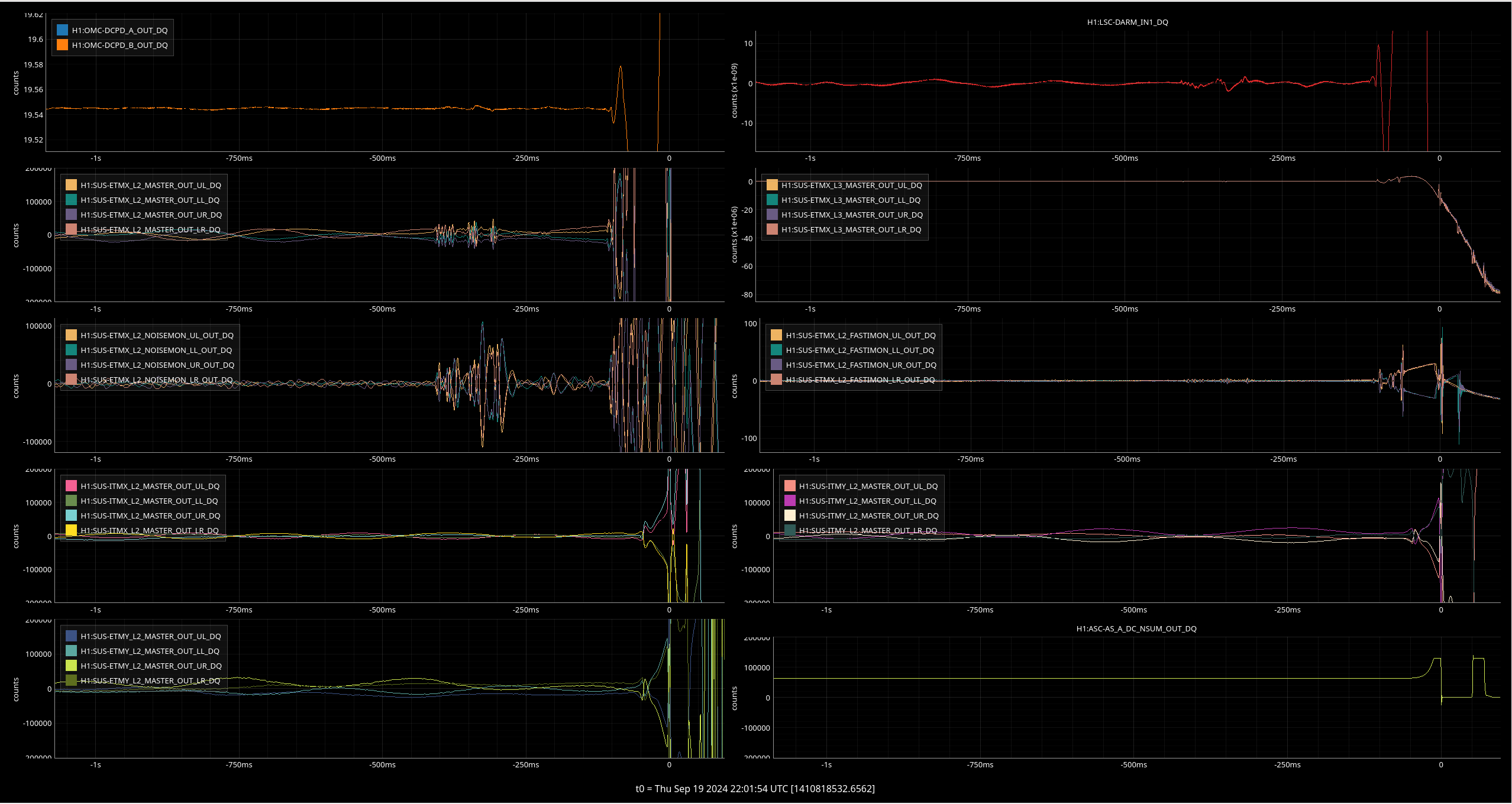
This one has our normal ETMX glitch and a slight DARM wiggle, but we still have no idea why.
Observing 2259UTC. Full auto relock.
Vicky, Camilla, Naoki, Sheila
After our first trial of running ADS for OMC 3 MHz to align ZM5+6 (80114), we came up with a hypothesis of why this didn't maximize squeezing. We are trying to maximize the 3MHz Q signal, while the I signal is servo's. Changing the demod phase of the 6MHz rotates the IQ ellipse, in general anti-squeezing is at the demod phase where Q is maximized and squeezing is near the phase where Q is minimized, but because the 3MHz is off resonaonce in the OPO the best squeezing is slightly away from the minimum.
If alignment changes didn't change the squeezing angle (for a fixed demod phase), then running ADS to maximize the 3MHz Q signal should be increasing the throughput of 3MHz, which would mean that the OPO is better aligned to the OMC. But, we see that changing the alignment changes the squeezing angle. This means that moving the alignment to maximize RF3 would only work as an alignment servo if the RF3 demod phase were updated to keep the squeezing angle constant.
So our plan for today was to run the ADF servo to feed back to RF6 demod phase and keep the squeezing angle correct while we run ADS to adjust the alignment of ZM5+6. The servos worked fine, but again didn't give us good squeezing. We think this is because the ADF servo didn't actually do a good job of keeping the squeezing angle set to minimize shot noise.
We ran ADS for 3MHz Q to ZM5+6 and the ADF servo to adjust RF3 demod phase based on H1:SQZ-ADF_OMC_TRANS_SQZ_ANG, which moved ZM5 pitch by -19, ZM5 Y by +3urad, ZM6 P by -135 urad, and ZM6 Y by -5 urad, and moved H1:SQZ-CLF_REFL_RF6_PHASE_PHASEDEG by -45 degrees. After this finished we ran SCAN_SQZANG to readjust the squeezing angle (RF6 MHz) to minimize shot noise at 300 Hz, which indicated that the demod phase change we needed to compensate for the alignment shift was actually only 25 degrees. So, thinking about ZM6 P, we see that an alignment would require a 0.2 degree shift in demod phase, and also causes a similar sized error in the squeezing angle read out by the ADF.
After all this, we went back to our best squeezing by running scan alignment and scan sqz angle, then moved ZM6 by -100 urad and re-ran scan sqz angle, we needed to shift the 6MHz demod angle by -16.4 degrees.

The line heights of some of the PCAL lines in the cleaned channel have been much higher than actual at the begining of todays' locks (attachment 1). The relock yesterday didn't have it (attachment 2). Looks like this was potentially fixed a month ago - alog79558, but perhaps the locks from today are too short?
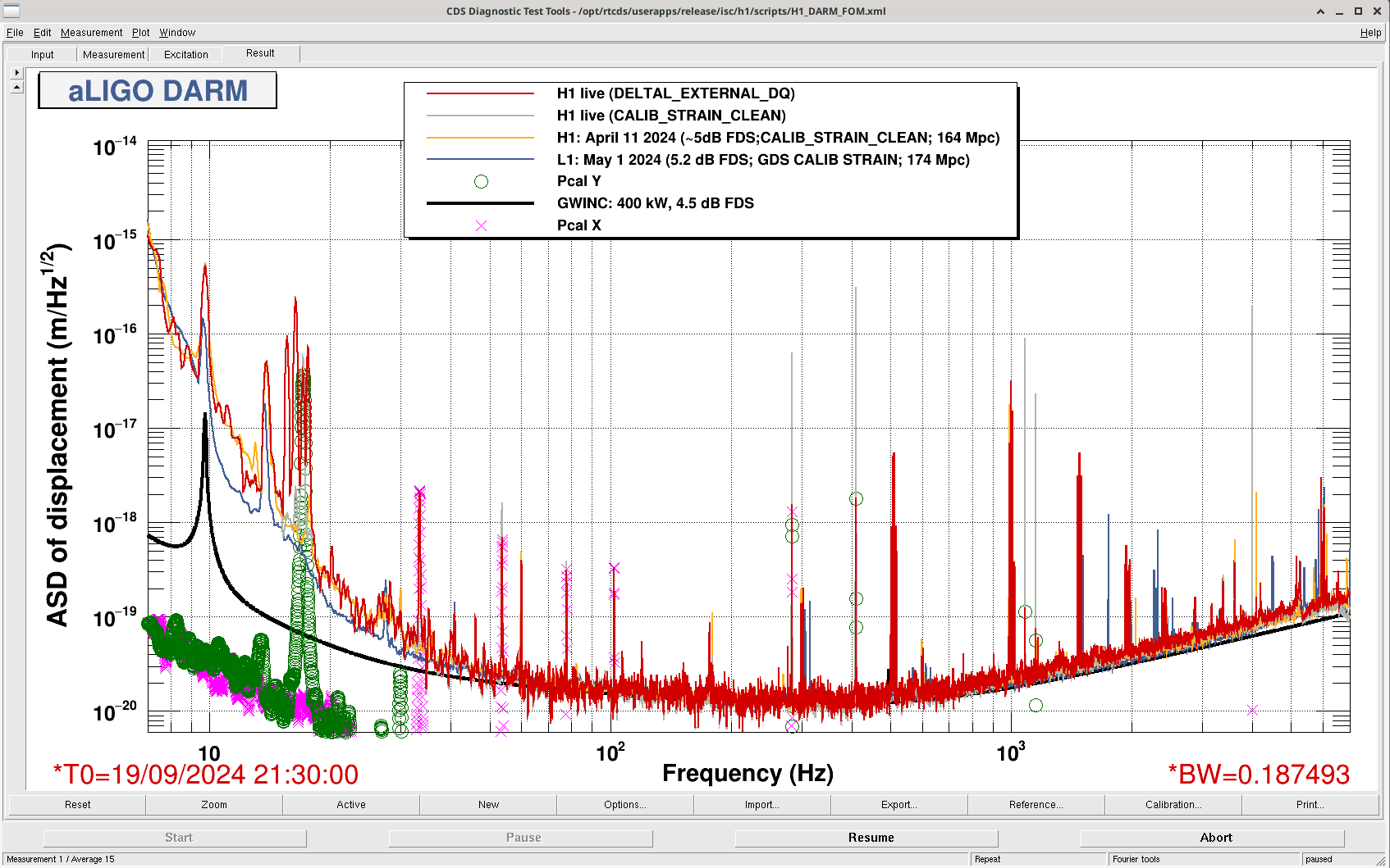
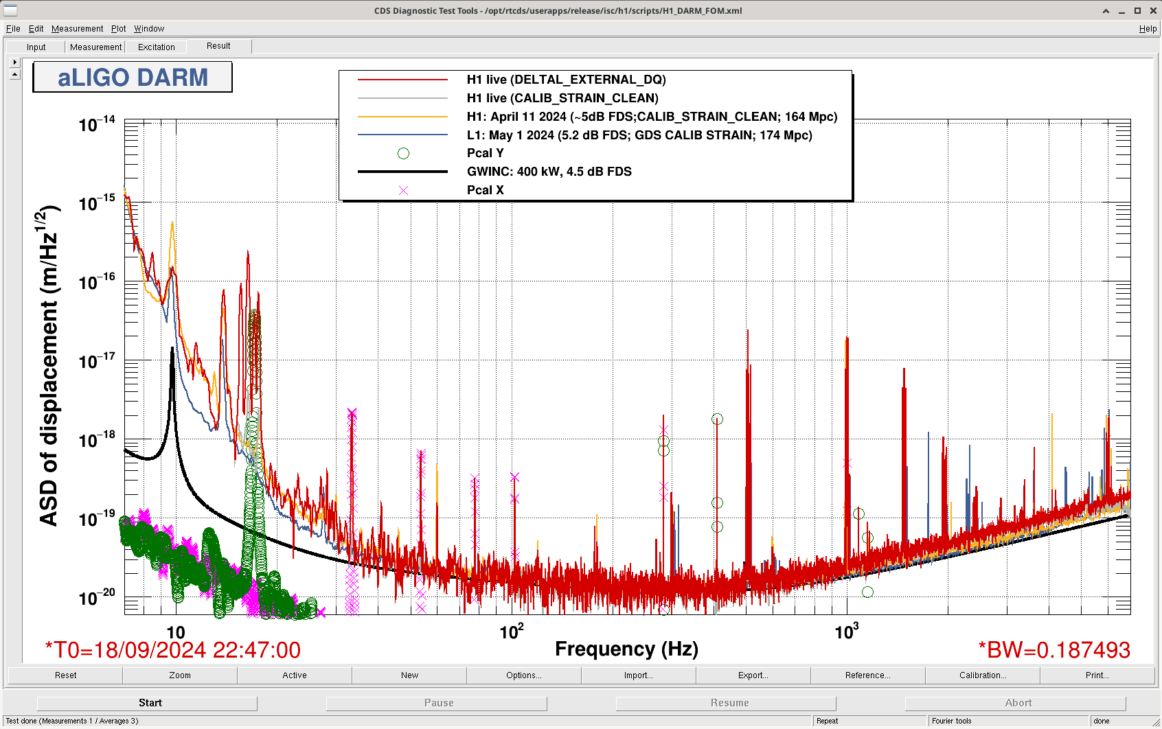
This is most likely caused by a slightly different issue that what was addressed in LHO aLOG 79558. In some instances, the line subtraction TFs are not updating properly at the beginning of lock stretches. I am working on a fix for this.
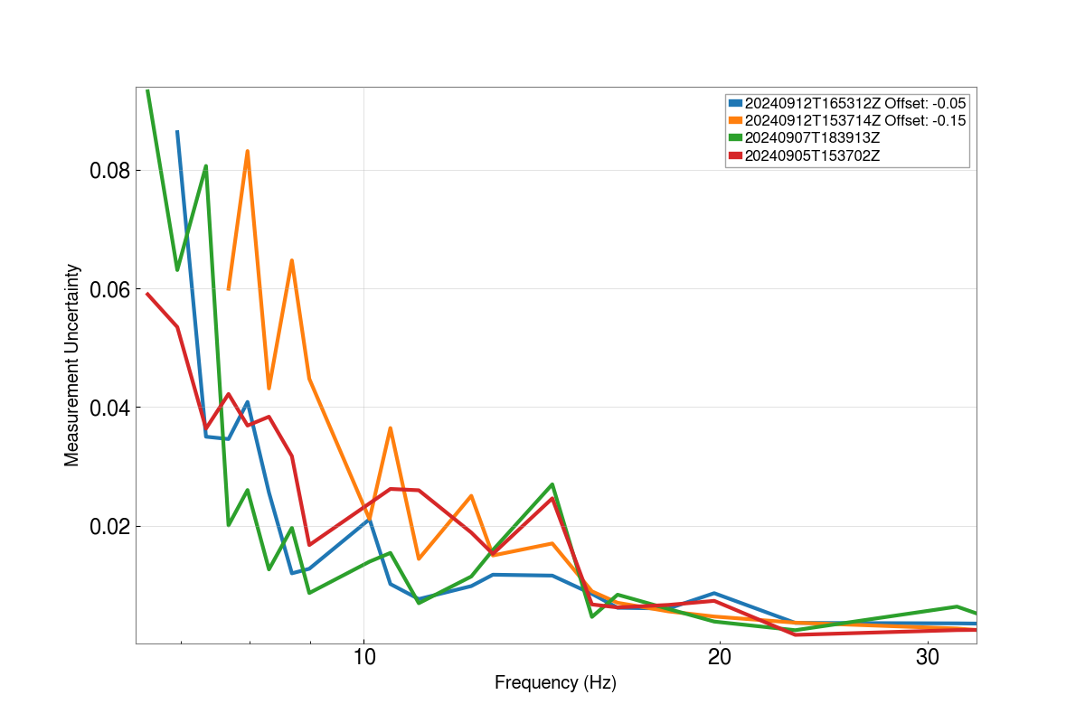
Sheila, Louis, Francisco
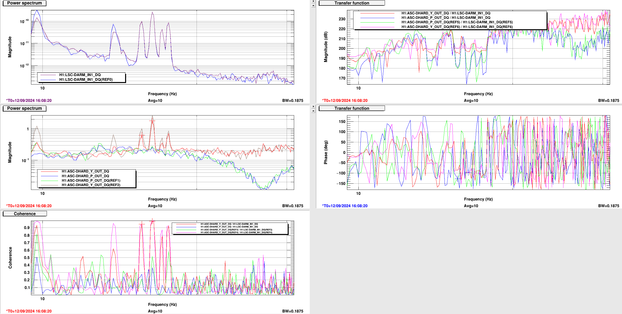
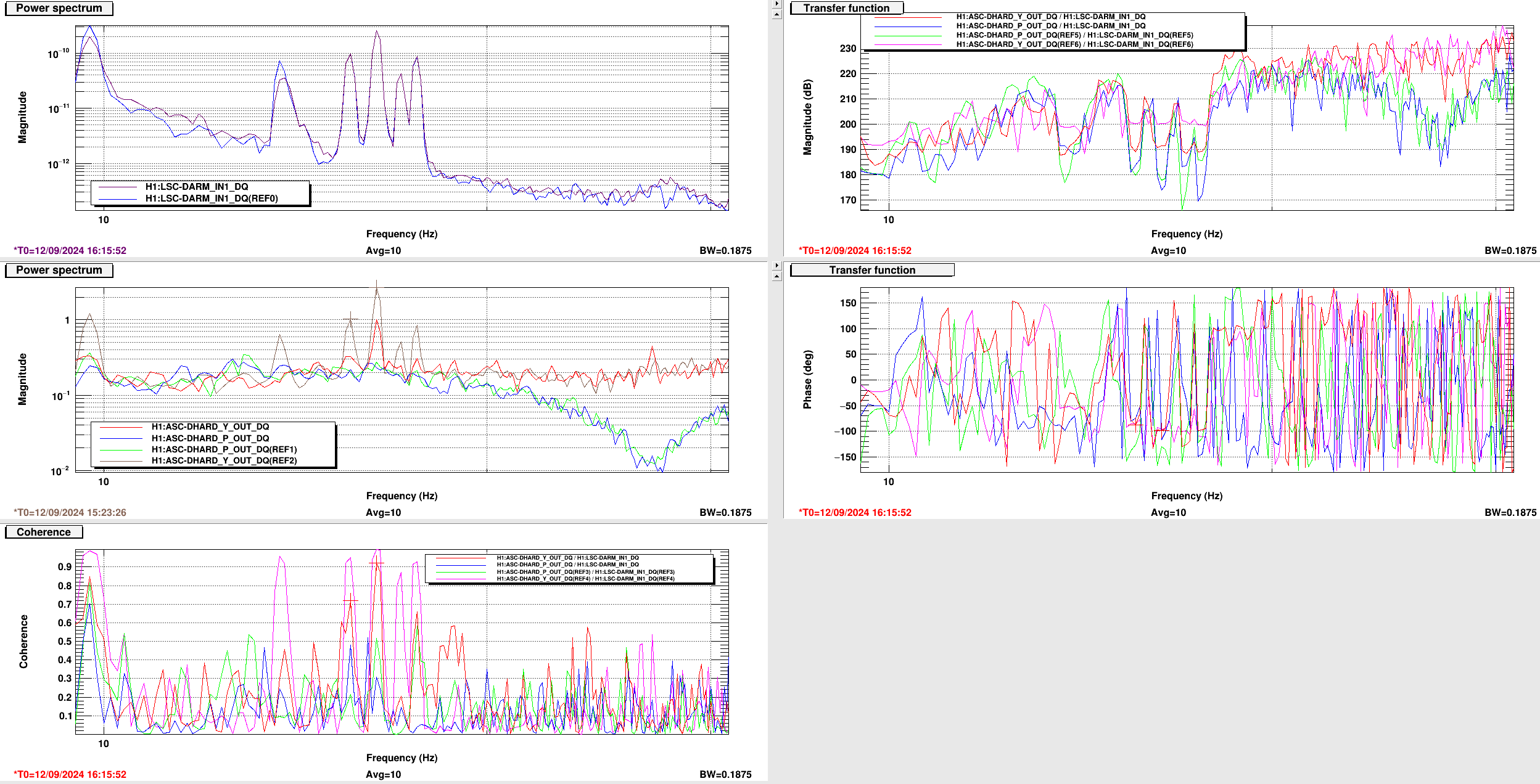
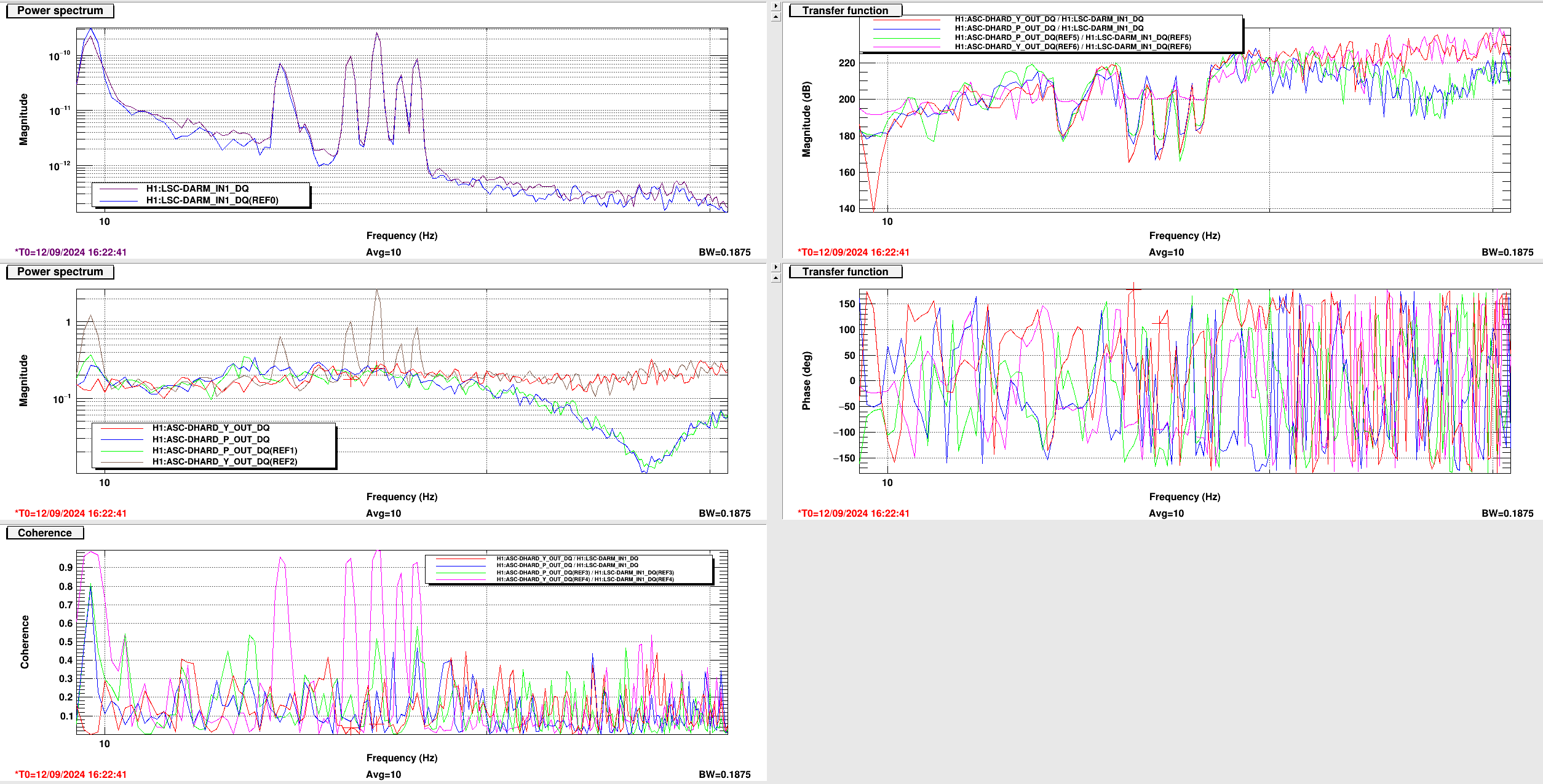
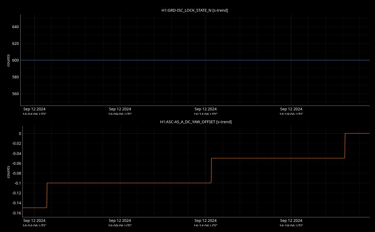
Following LHO:80044, we measured ASC-DHARD_P(Y) for different ASC-AS_A_DC_YAW_OFFSET and found the loswet values of DHARD_Y at an offset of -0.05.
The "DTT_AS_A_*.png"s show the outputs of DHARD_DARM_240912 when changing AS_A_DC_OFFSET with a reference trace for when the offset was nominal (ASC-AS_A_DC_YAW_OFFSET = -0.15). Each trace has a marker at the two highest peaks in the ASC-DHARD power spectrum (the middle plot on the left). DTT_AS_A_neg0_05 shows the lowest value in the power spectrum compared to DTT_AS_A_neg0_10, while preserving coherence (lowest-left) and phase values (middle-rigt), compared to DTT_AS_A_0. AS_A_NDSCOPE corroborate on the times at which these measurements were done and the values for AS_A offset.
Confirming that the four TFs traces corresponding to reports
were all done under a thermalized interferometer.
-Mattia, Sheila
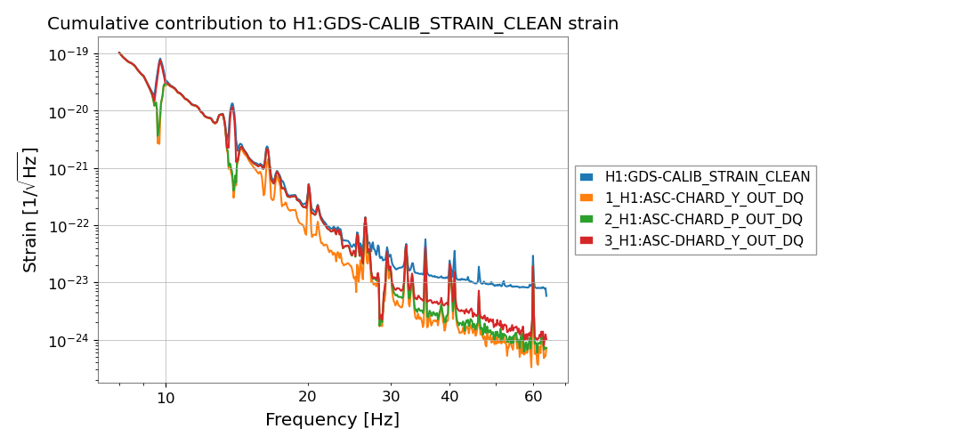
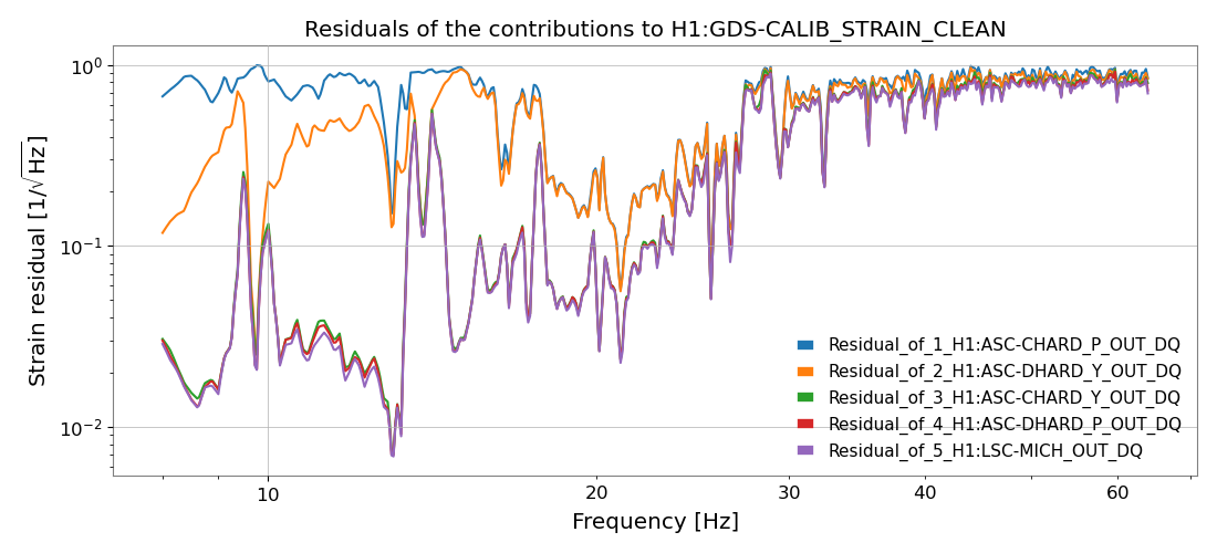
We have written a python script to compute the full matrix of power spectral densities and cross-power spectral densities between a given channel, i.e., DARM, and a set of auxiliary channels. The code can be find at this repository https://git.ligo.org/mattia.emma/cross_psd which includes a README file describing how to run it.
The main arguments the user has to pass are the start time (in GPS time) and length of the data to retrieve from gwpy, a list of channel names and the starting frequency for the strain plots.
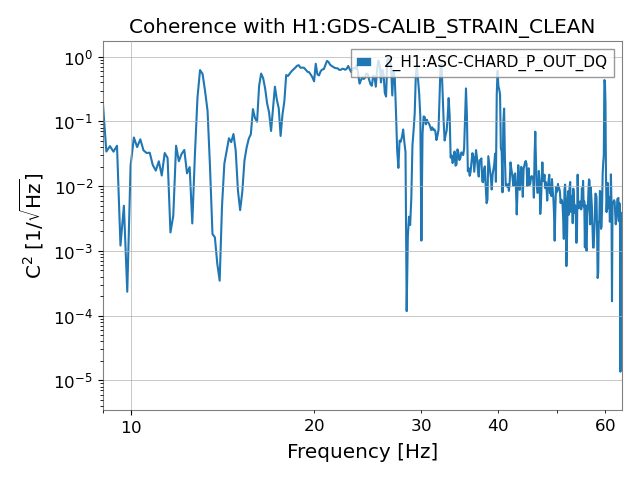
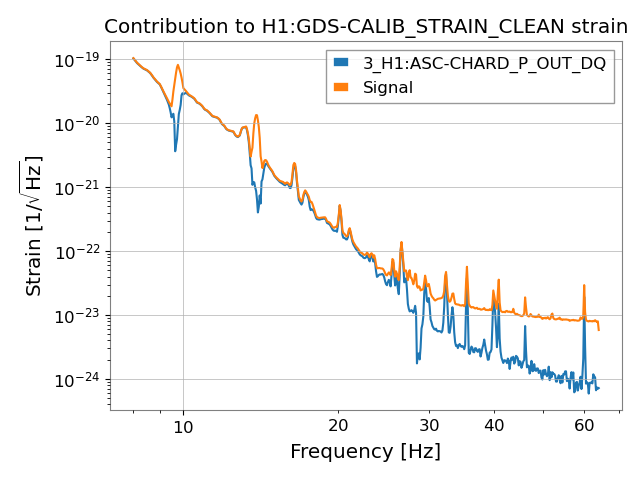
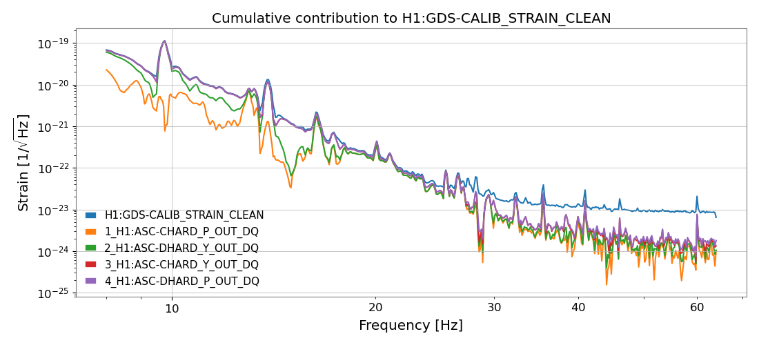
The code creates five different types of plots using the coherence and cross-power spectral density matrix. The final result of the code is a coefficient for each frequency value expressing the algebraic sum of the contributions of all the auxiliary channels to DARM considering the cross-power spectral density terms. It also computes the coherence between the single auxiliary channels and the DARM channel, which are the diagonal terms in the cross-power spectral density matrix.
The five kinds of plots are:
All of these plots can also be created using as a main channel any auxiliary channel instead of DARM, e.g., if one would like to study the correlation between auxiliary channels. Each plot name also includes the start and end GPS time of the data used for them.
Comments are welcome. As a next step we would like to implement interactive plots to allow the user to include/exclude lines from the plots.


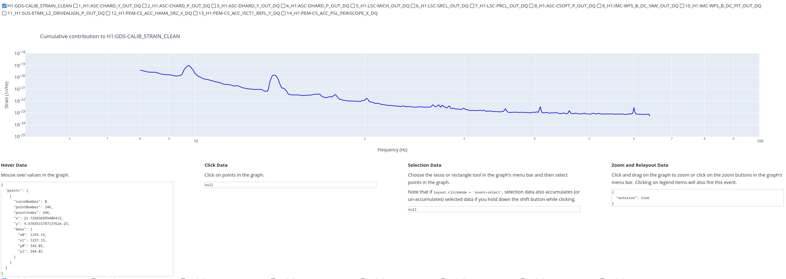
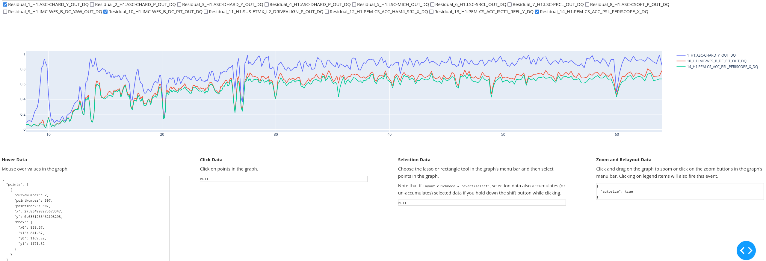
We have now added a code and instructions to the GitLab to obtain an interactive plot on one's local server.
The webpage displays two plots as shown in the attached screenshots (third and fourth image) and allows the user to select which lines to show through a checklist. It is possible to save a screenshot of each plot, zoom-in and out, and hover over the data.
The two included plots are (1) a plot of the normalized residuals between the DARM noise and the cumulative strain contribution of the auxiliary channels , and (2) "Plot 2" from the above aLog, showing the cumulative contribution of the selected channels to the DARM noise.
The code is publicly accessible on GitLab at Cross_psd .
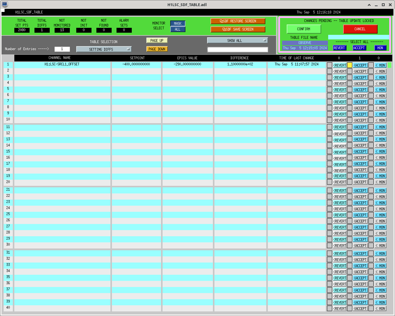
Vicky, Sheila, Naoki
First we tried SRCL offset of -400, which looked good in yesterday's FIS SRCL offset measurement 79903. We took the calibration measurement with SRCL offset of -400 in 79911, but Louis reported in the mattermost that there is a large optical spring in the sensing function. Also, FDS with SRCL offset of -400 is worse than nominal. Vicky will add more plots for this.
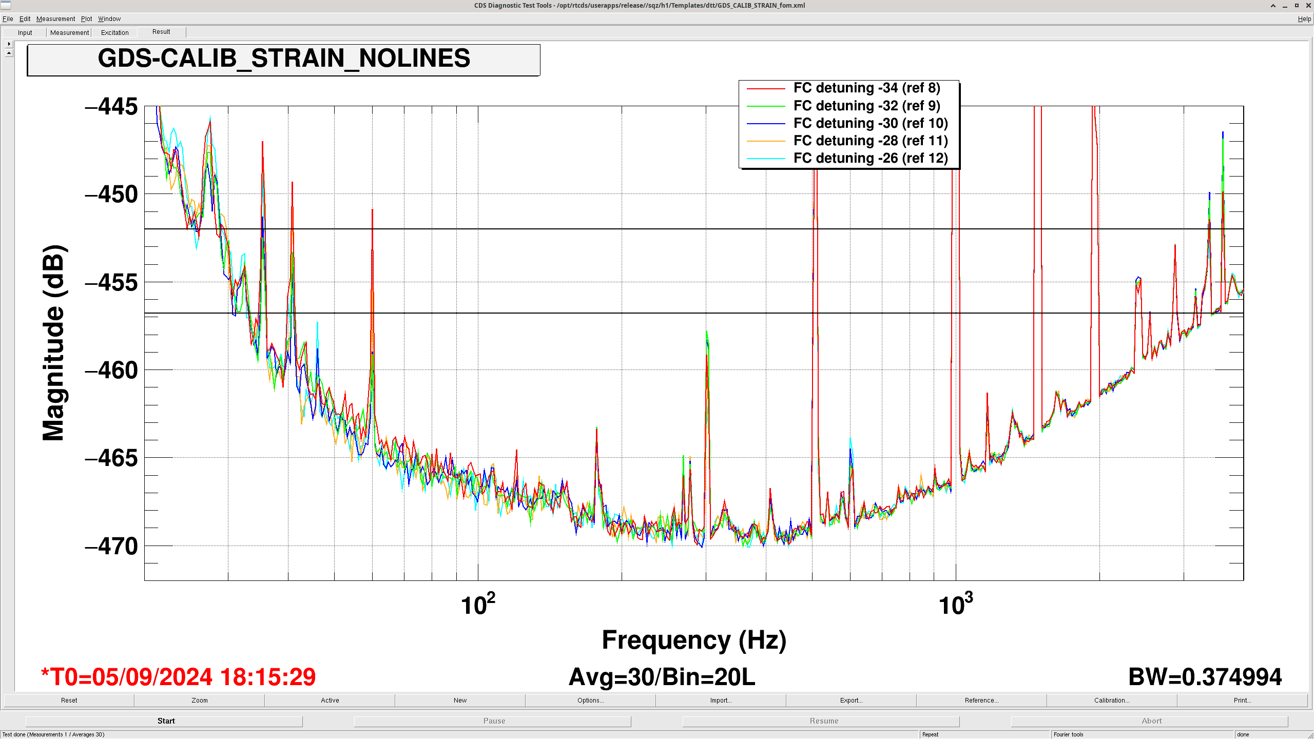
Then we decided to change the SRCL offset to -290 and optimized FC detuning. This improved the sensitivity below 100 Hz as shown in the first attachment and improved the range by ~5Mpc. The optimal FC detuning changed from -34 Hz to -28 Hz and this could be because of SRCL offset change and arm power change.
After FC detuning improvement, we took the calibration measurement with SRCL offset of -290 in 79922, but the measurement did not make sense according to Louis so we took an another calibration measurement with SRCL offset of -290 in 79928.

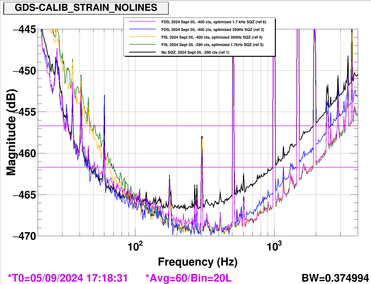
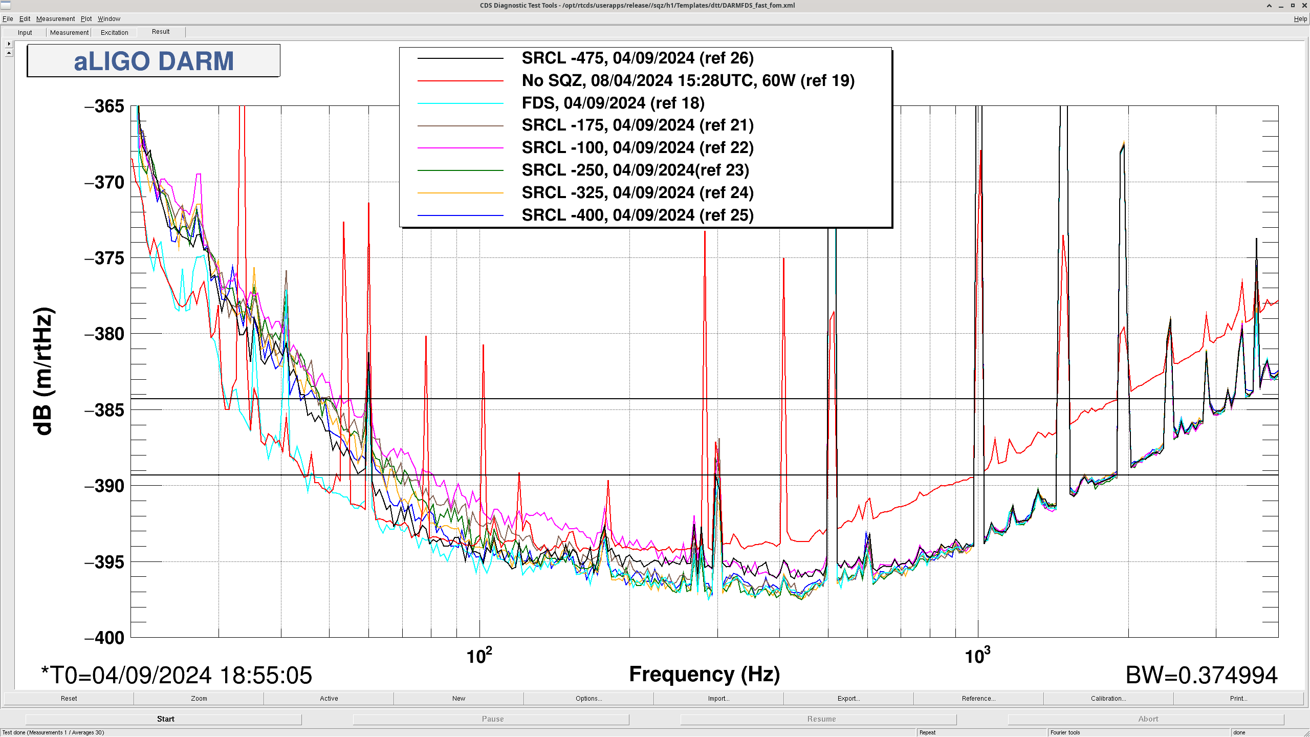
Following up with some FIS SRCL measurements from today as we were navigating how to best optimize SRCL offset for squeezing, which gives best sensitivity around 100 Hz.
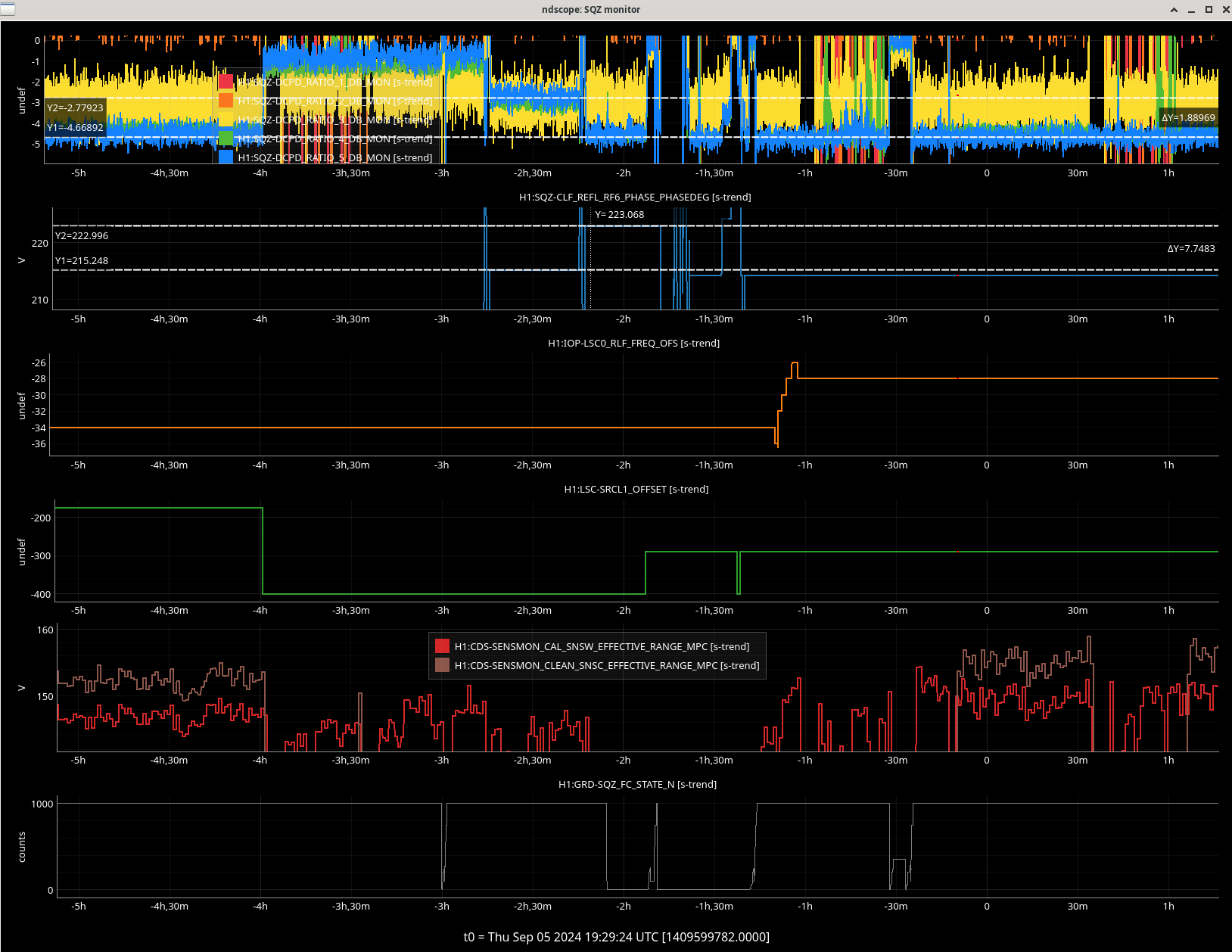
Blue & purple traces - When first looking at SQZ after re-calibrating at -400 counts srcl offset, SQZ looked kinda v-shaped, like as if the SRCL detuning is big. We first tried optimizing the sqz angle for the bucket (blue, CLF RF6 demod phase @ 222 deg), then tried to optimize high-freq sqz (purple, CLF RF6 @ 215deg). For this SRCL offset at -400 counts, with about (222-215=) 7 degrees difference on the CLF RF6 demod phase (bad estimate is ~3.5deg diff on sqz angle), this changed the kHz squeezing level by about 1.9dB. See the trends on this screenshot.
Yellow trace - We then tried to see if FIS + SRCL @ -400 counts was the same as yesterday lho79903 and yes it was same. But zooming into yesterday's plots, it looks like this -400 SRCL offset setting (yesterday's blue trace) was actually not a great spot (already well passed zero detuning), as there is a little bit of ballooning between 100-200Hz that we did not notice yesterday.
Given that squeezing, and also calibration, saw that this SRCL offset @ -400 cts had a bad spring effect, we backed it off to -290 counts and took another cal meausrement. We chose -290 to be ~halfway between the -475 ct (pink) and -100 ct (black) settings tried yesterday (see dtt). For -475 ct and -100 ct, we realized today that DARM between 250-500 Hz had about the same level of anti-sqz coupled in by the SRCL detuning. Unsure if this means they have the same physical detuning, this is something we will try out in quantum noise models to understand better.
Green trace - shows FIS + SRCL @ -290 counts. It is where we expected from yesterday. Leaving it here.
In summary, today we tried a few methods of "optimizing srcl detuning," to get it closer to 0, but also realized we need to think more carefully with quantum noise models like, what is the easiest / most sensitive metric for squeezing to see the srcl detuning.
We then moved onto FDS + SRCL @ -290 counts, and optimized the filter cavity detuning, as Naoki describes above.
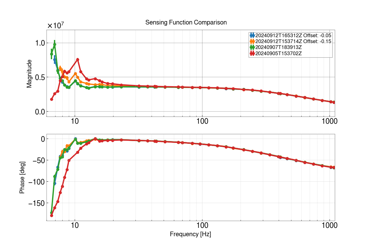
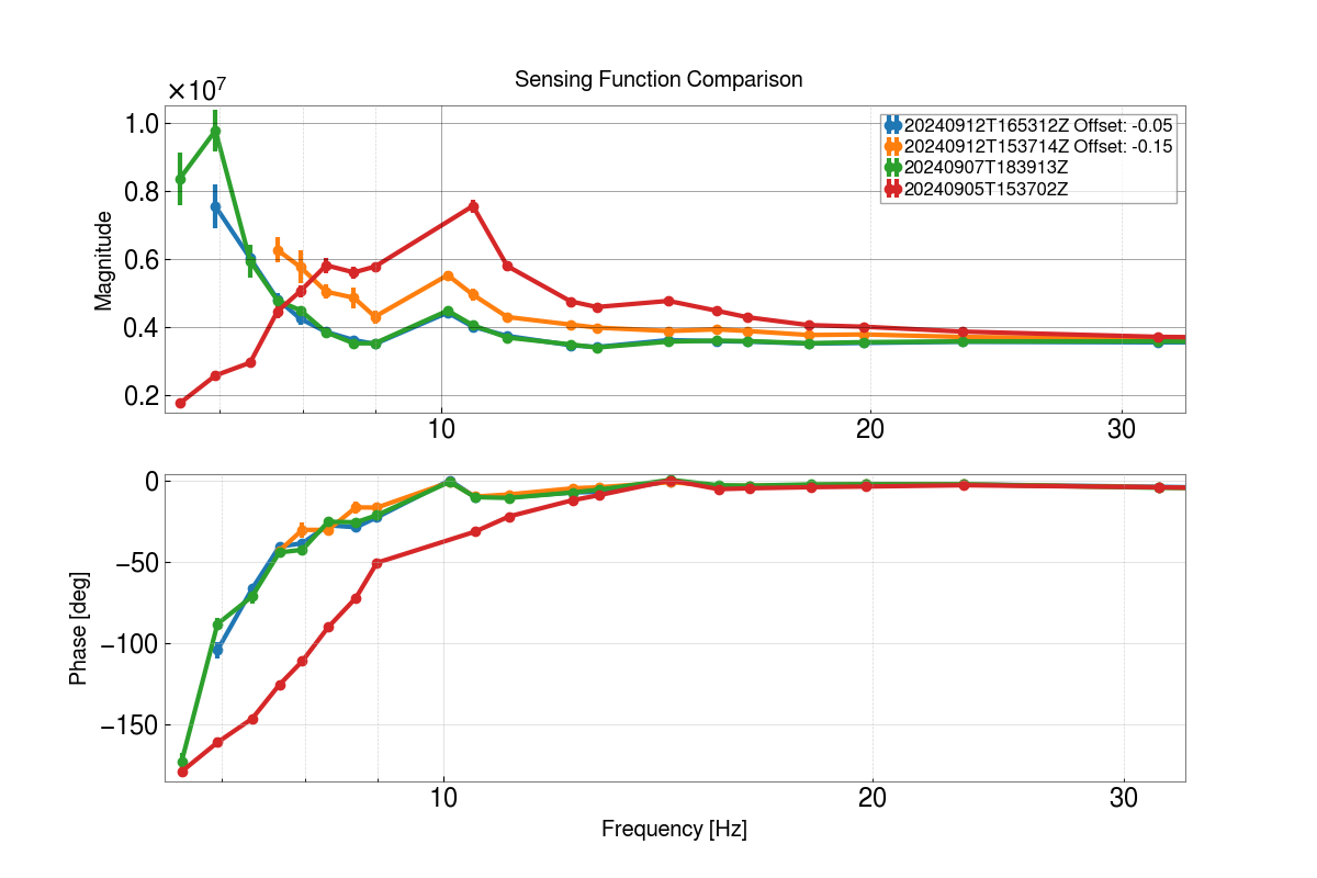
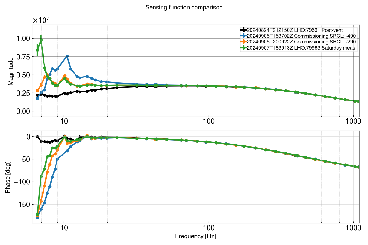
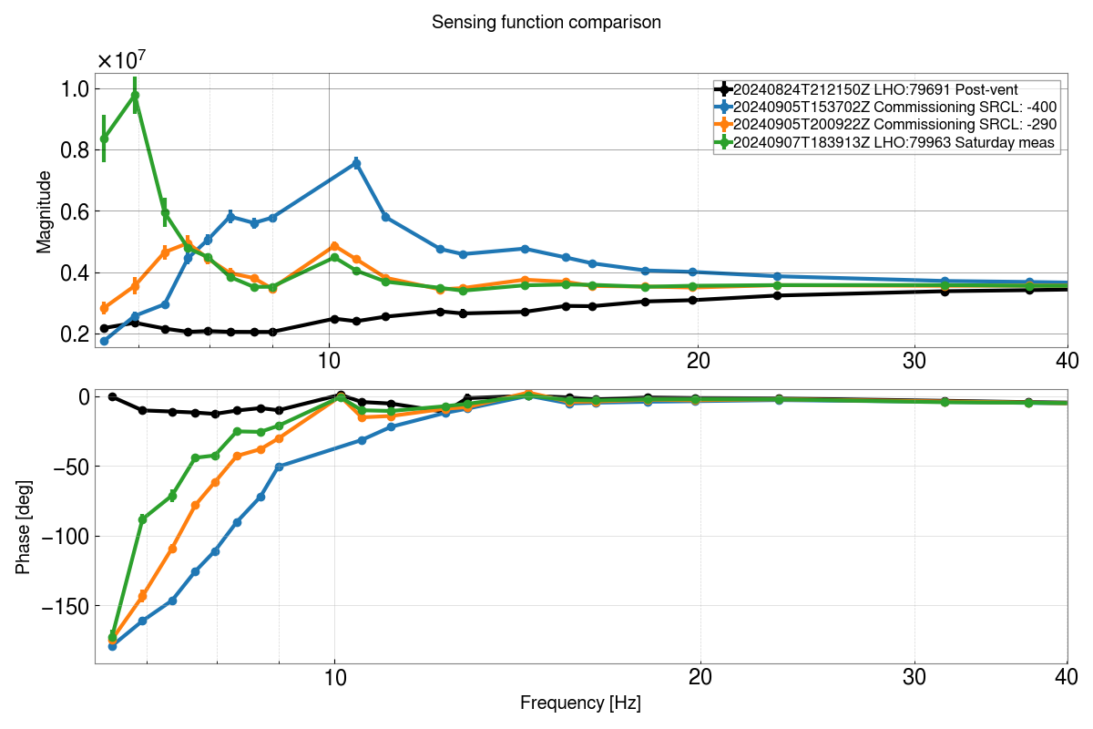
Adding plots of the sensing function. From these measurements, we see that the sensing function is also an indicator of bad/good SRCL offset. Additionally, *something* changed from Thursday to Saturday, as seen in the Saturday calibration measurement trace.
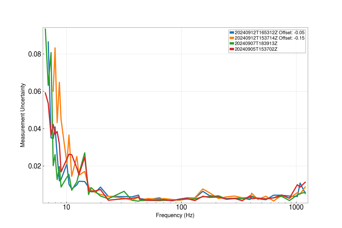
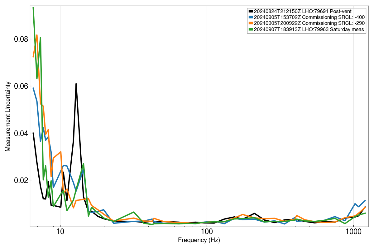
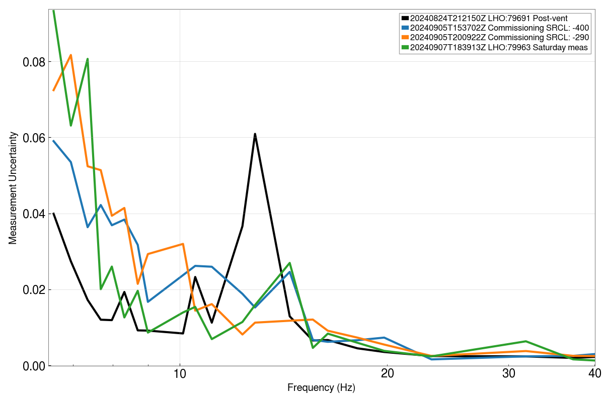
Figures (1) and (2) are the different sensing functions where the second figure ranges from 0-40 Hz. The uncertainties of each measutrement are plotted in figures (3) and (4), where figure (4) ranges from 0-40Hz.


