Sheila, Vicky, Camilla, Naoki
We tried ADS using ZM5+6 and OMC3MHz Q. This is a similiar strategy to what Masayuki tried in 64458, but a different implementation. This worked and made the squeezing worse, so we think that for some reason aligning the OPO to the OMC is not the best for squeezing right now.
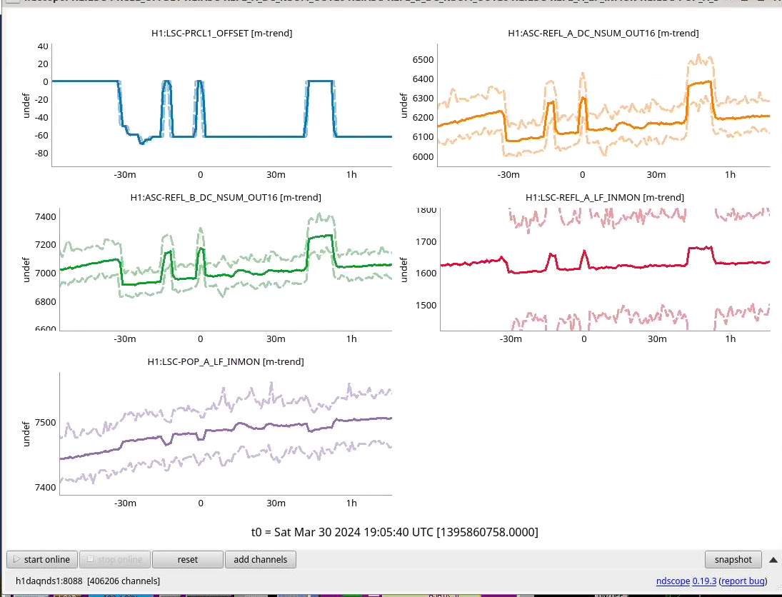
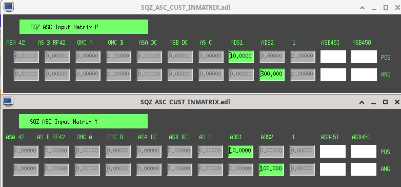
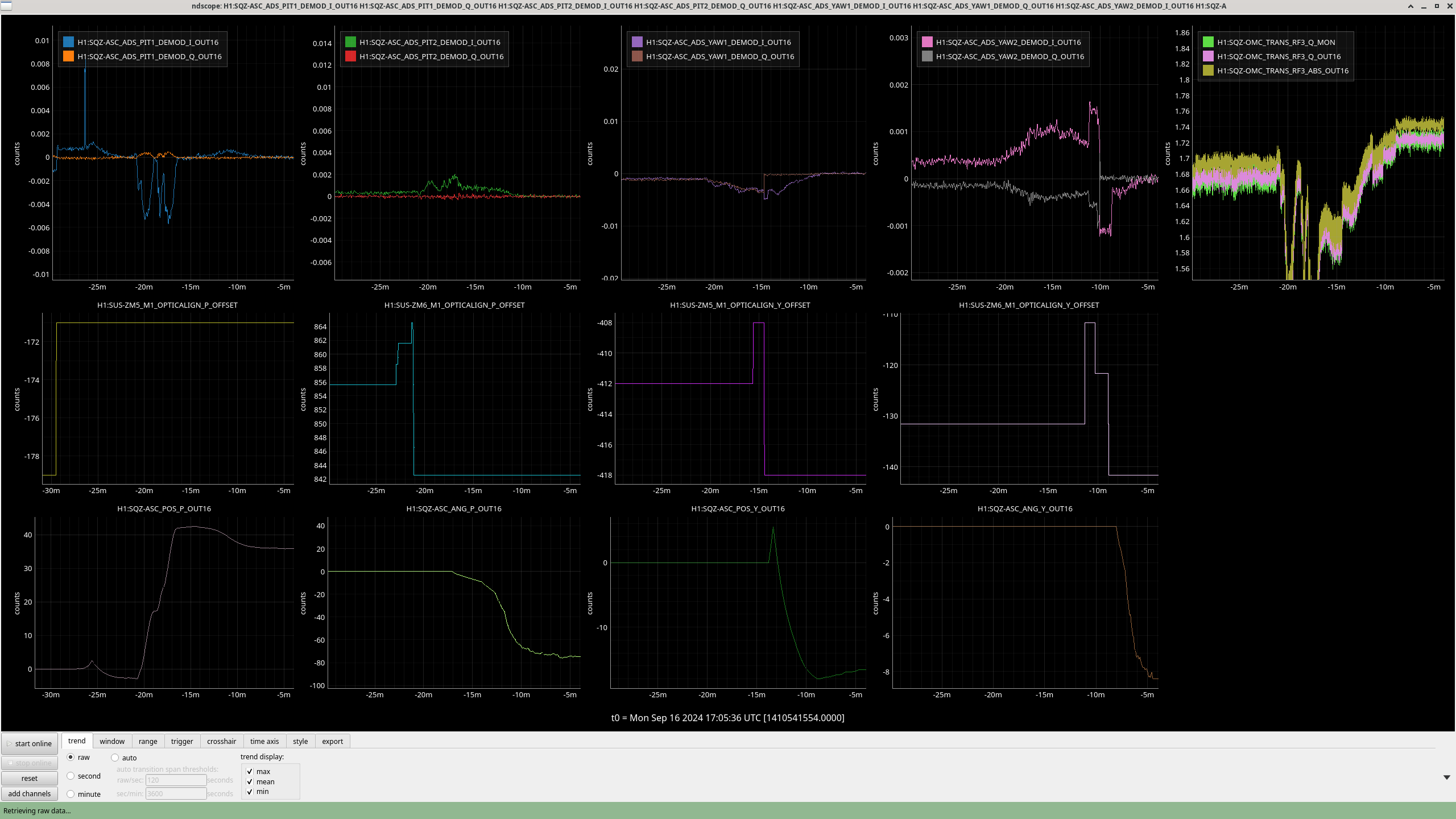
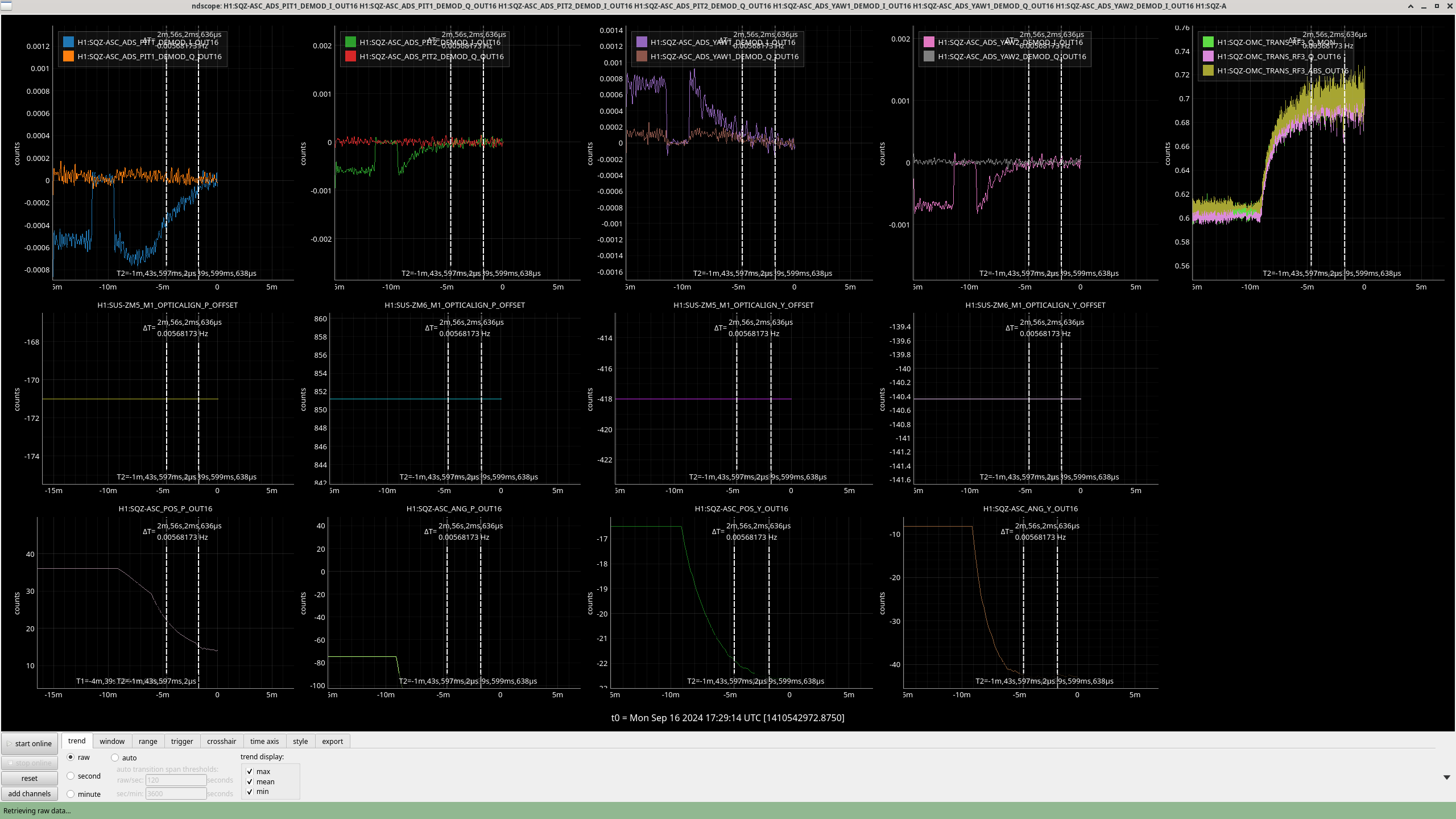
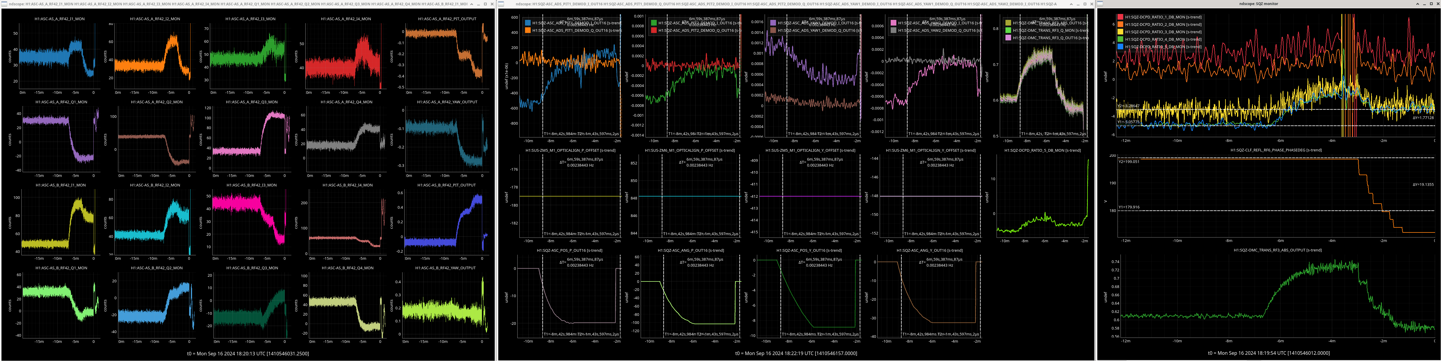
We saw that we can dither ZM5+6 with 3 counts out of ADS, which doesn't degreade the squeezing level (see Camilla's second attachment in 80113), but gives us good SNR in the 3MHz signal. We think it would be fine to turn this down by a factor of 3, and still have enough SNR. We added bandpass and low pass filters to ADS, and adjusted the phases, and closed the loops. The attached screenshot of the input matrix was used with an ASC_MASTER gain of 1, these loops converged slowly over a few minutes and did a good job of maximizing the RF3MHz, as shown in the next two attachments.
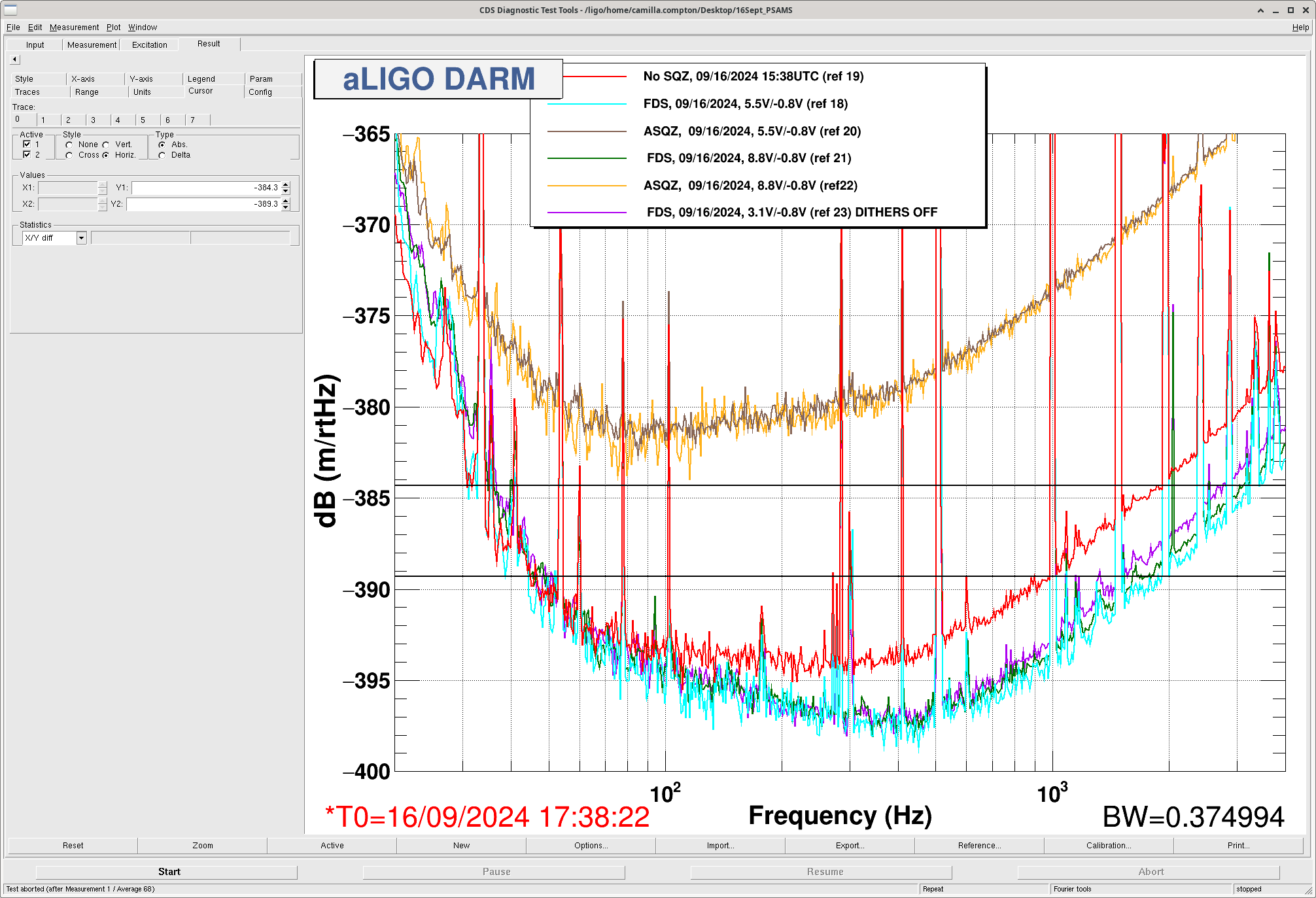
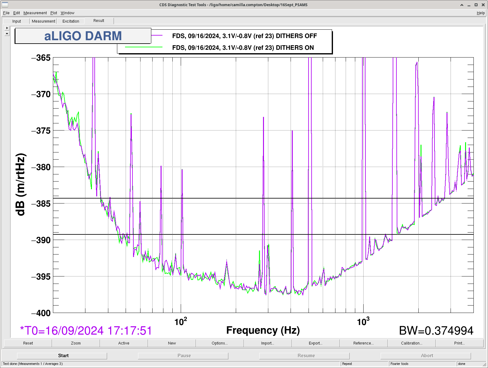
We tested this first with anti-squeezing, where it seemed to keep the level of anti-squeezing high. Then we tried it with squeezing with the PSAMs settings from the OMC test (see Camilla's alog), here the ADS matimized the RF3Q, but it added scatter at low frequency andmade the high frequency worse. We turned the ADS off to run the sqz angle optimization script (sets SQZ angle according to 300 Hz sqz blrms), then engaged the ADS again, still the squeezing was worse than what the scan alignment script had done.
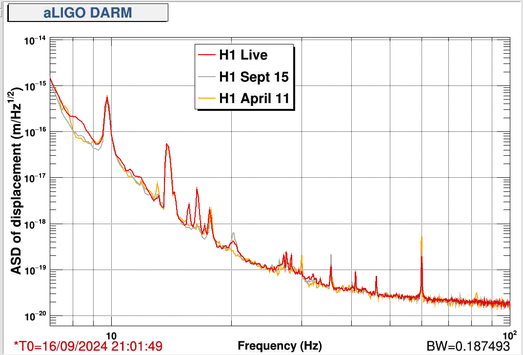
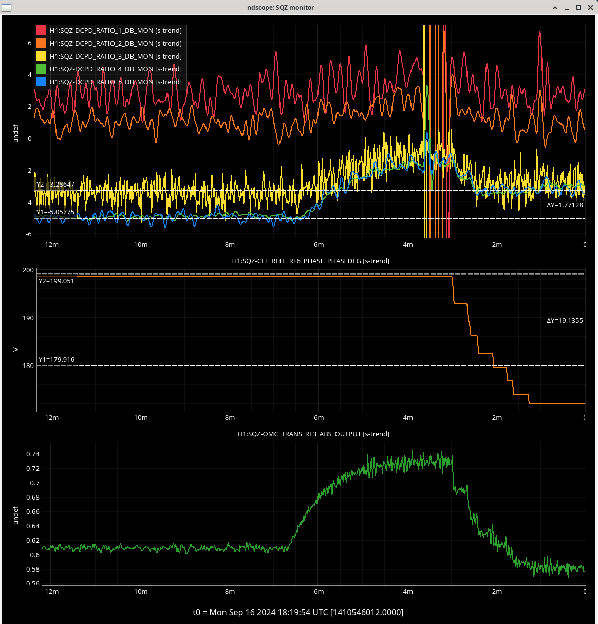
After Camilla reverted the PSAMs to the settings we've been using for observing recently, we tried ADS again, which again maximized RF3 but made squeezing worse. We moved the RF3 demod phase by about 20degrees after the alignment shift to reoptimize the squeezing, (the alignment has a strong impact on that demod phase), but the squeezing was still 1.7 dB worse than what Camilla found with manual alignment. Vicky's screenshots show the impact of running this ADS and them optimizing the sqz angle on squeezing and RF3 MHz here, and a comparison of the ADS and AS42 signals here.


Work to be done today:
CDS - [ISC, SUS] EX - Swap the SUS signals from the 18 and 20 bit 8ch DAC's over to the LIGO 32 bit 32ch DAC at SUS-EX. (Marc, Fil, Daniel) WP 12079Access Laser LVEA TCS table tour (Camilla, TJ?) WP12080TCS - 8a to 8:15a [LVEA HWST] Reinstall Hartmann Sensor Masks On TCSHT4R HWS Table (Camilla)VAC- [CP1 (Y Arm) / CP2 (X Arm)] Outside Work -- Radiator (or vaporizer) examination. (Gerardo, Travis, Jordan) WP12083 -- postponed
VAC- [CE/MR] Power down the ion pump controller, to then move the controller within the rack, and connect new signal cables. (Jordan, Travis, Gerardo) WP12085New Guardian node TEST_NOTIFY. (TJ) WP12091SEI - [EX] Recenter BRSX. Turn on picomotor, adjust BRSX adjustment mass. (Jim) WP12088CDS- [PEM] Verify cabling for PEM sensors in the FCES. New cabling for Ham floor and beamtube accelerometers will be installed. (Fil, Dave) WP120898a SQZ: SQZT0 Realign PUMP AOM --Postponed
SQZ: [With IFO, Nominal Low Noise] Go to 0V psams with locked IFO turn off PSAMs driver (during IFO thermalization time). -- postponed