Noting observation of Operator team: high state locklooses seem to ring up violins.
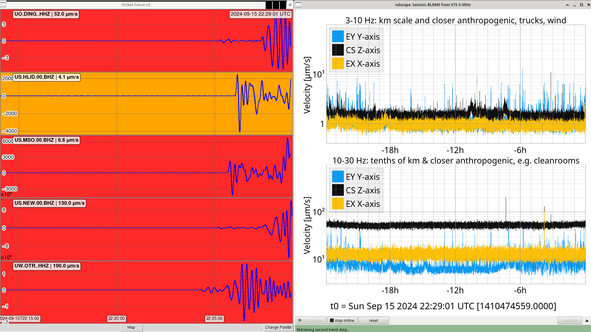
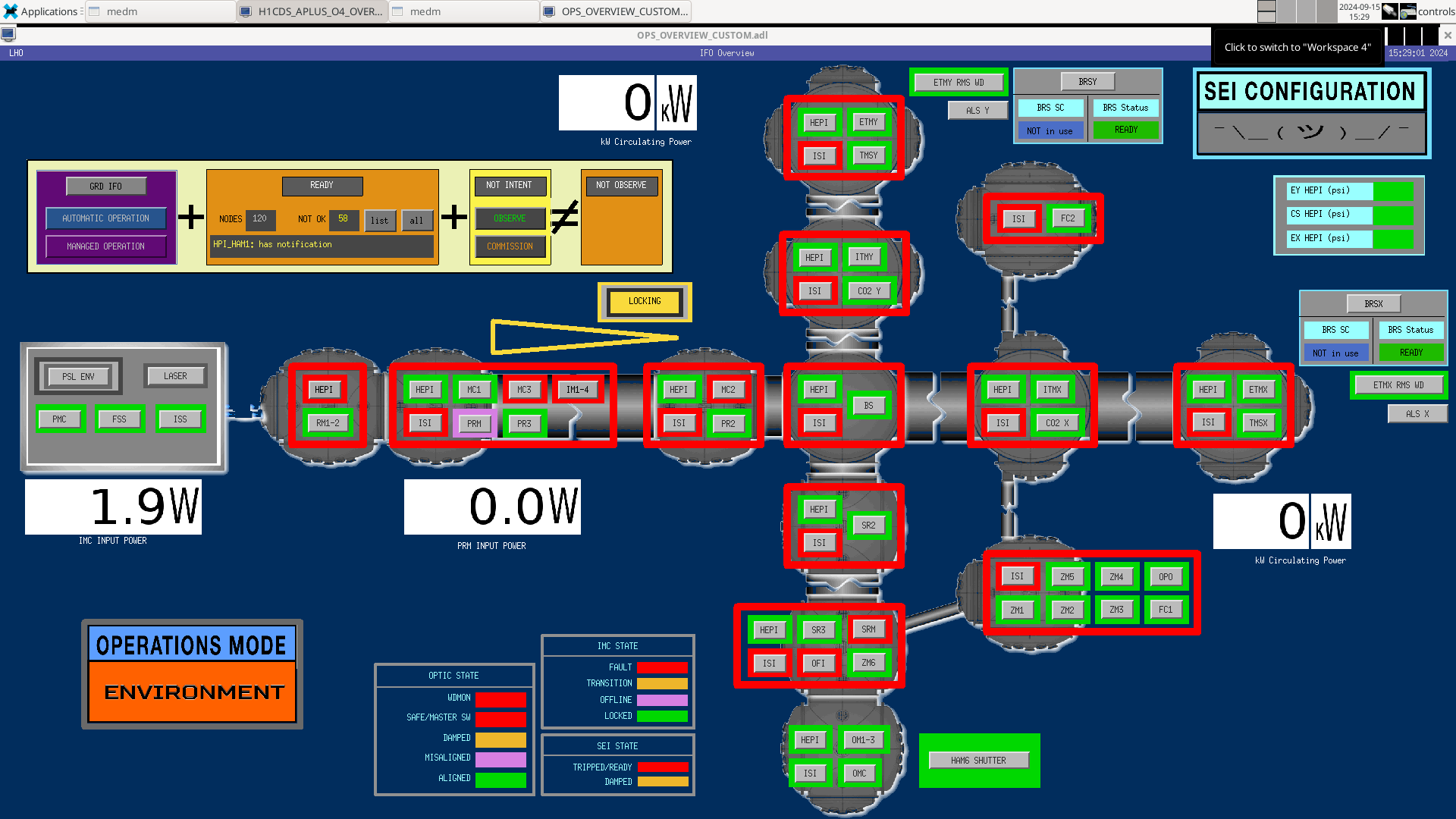
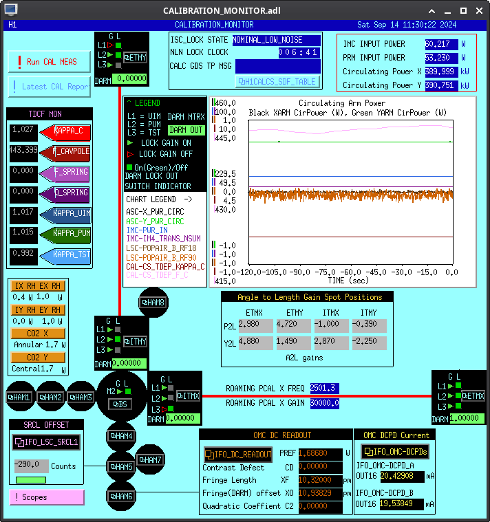
This morning at 1410522546 we lost lock from an EQ while at POWER_10W. Since then the violins have been rung up. The IFO has been in OMC_WHITENING damping violins for over an hour, so this does effect observation time.
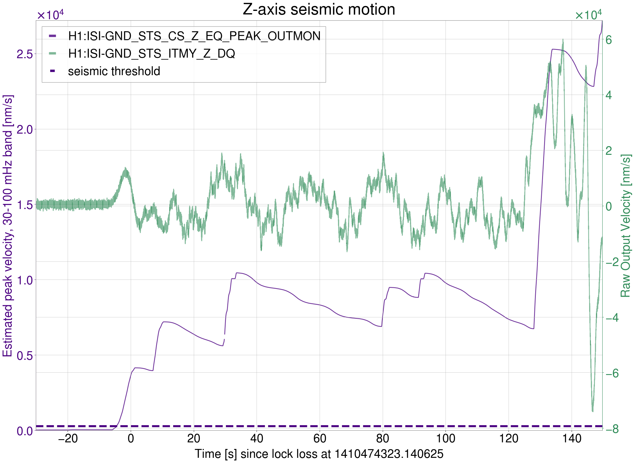
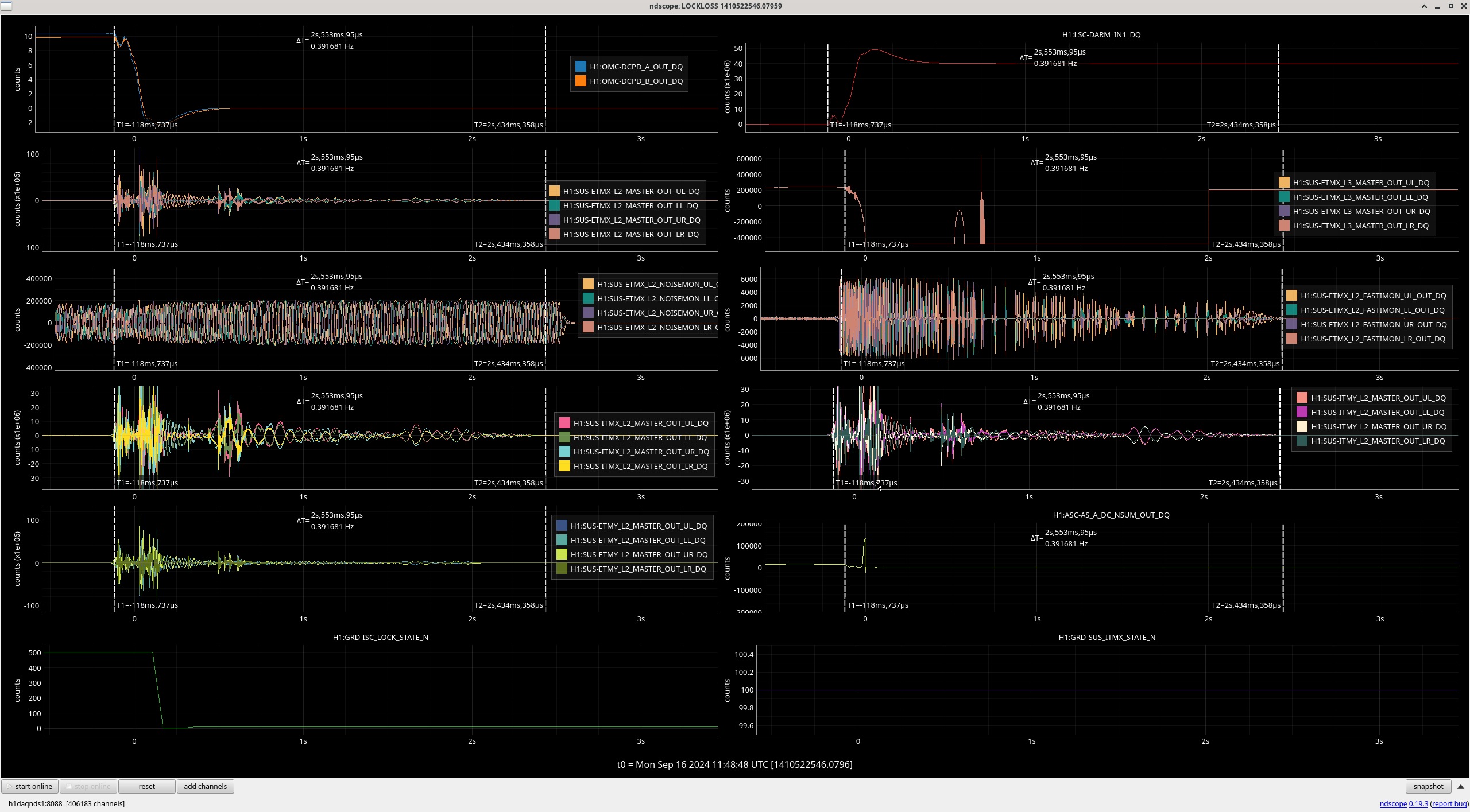
Looking at the SUS outputs at the lockloss time, it seems there is high counts on the MASTER_OUT channels, mainly in ETMY and ITMs, for the 2.5 seconds after the lockloss, plot attached. Unsure if this is feedback, glitching or active damping. Tagging ISC/SUS. Is this excepted?
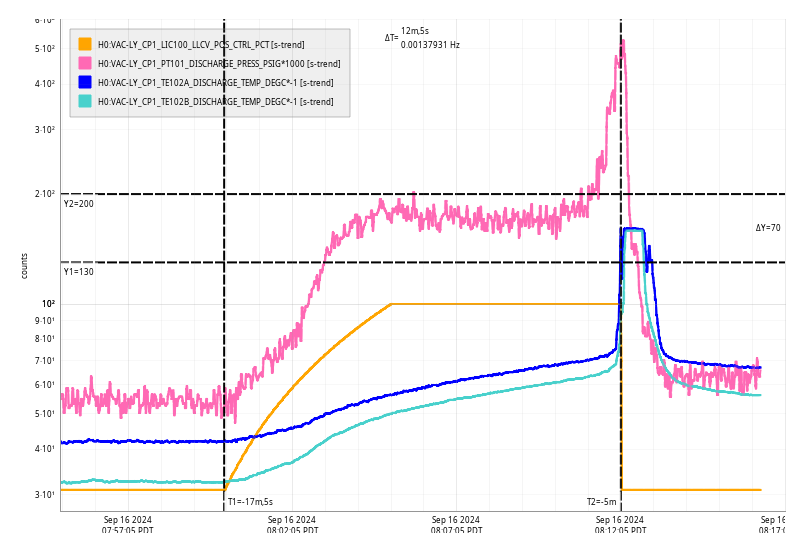
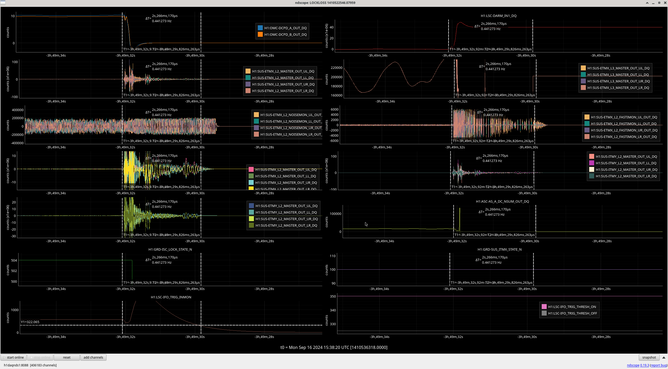
Shiela' notes that the lockloss trigger Jenne added in 45061 should not allow signals out of the quads once we loose lock. IFO_TRIG_INMON was at 550 and did not go below the 325 DISABLE(OFF) value until 2 seconds after this lockloss: plot. It goes down to 440 at the time of the lockloss, maybe we need to re-check what the trigger thresholds should be.
Ryan S, Rahul
Some of the modes are rung up and they are damping down nicely with nominal settings. We had to manually adjust ETMX mode8 slightly and now it seems to be dropping quickly.
I am keeping a close eye on ITMY mode 5/6 since they often change phase during earthquakes.
It looks like the OFF threshold is set rather conservatively, and it works fine (ish) for full IFO locklosses. However, this lockloss (and likely others like it) don't cause the trigger monitor to fall below the OFF threshold.
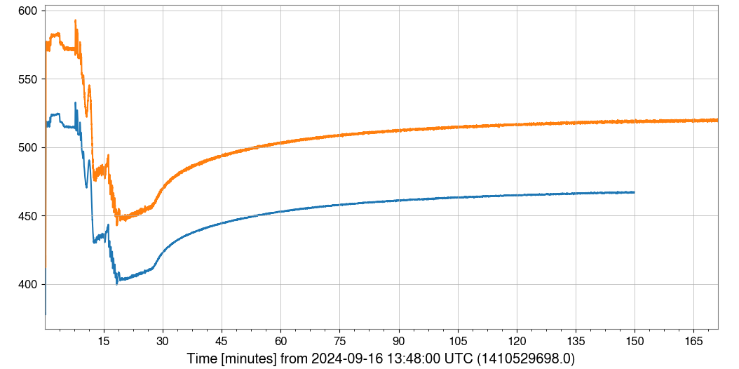
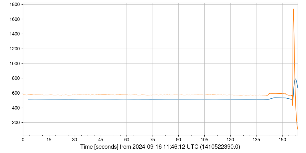
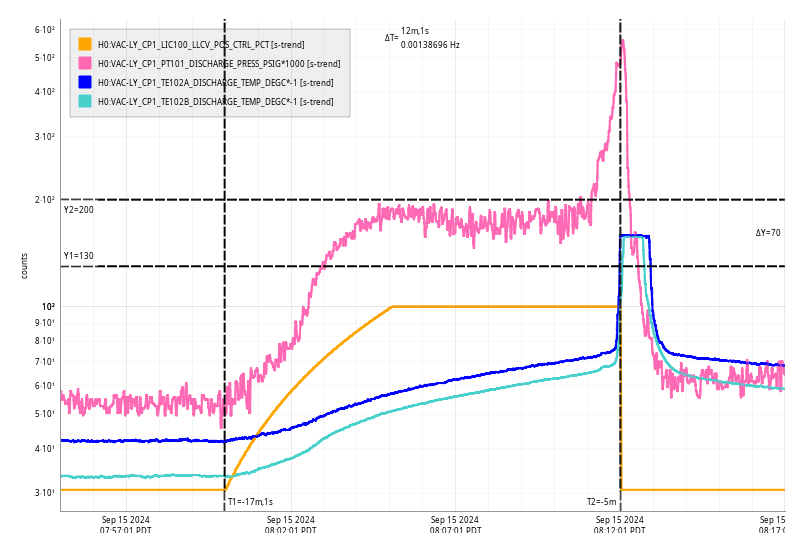
I've made some quick plots (one of a full lock acquisition sequence, and one of the 10 W lockloss that Camilla highlights), of what the OFF threshold would be if it were set to be 90% of the average of the monitor value over the last 3 seconds. For both plots, I take H1:LSC-IFO_TRIG_INMON (which comes from POP DC) and calculate an average value over the last 3 seconds. It's a moving average, so each data point in the avg is over the prior 3 seconds (and that's why the blue curve starts 2 sec later than the orange curve in the plots). I then multiply that average value by 0.9, so that I'm plotting what the candidate OFF threshold would be if it were 10% lower than the TRIG_INMON's average. Then, if orange crosses below blue, the trigger would go off and stop sending LSC, ASC, violin, and other signals to our actuators. Both plots have y-axes that are in units of counts of the LSC-IFO_TRIG_INMON channel. Orange is the raw TRIG_INMON, and blue is the candidate OFF threshold.
In the plot of the full acquisition, the candidate OFF threshold (blue) is always lower than the monitor value (orange), so it would not have mistakenly thought that we lost lock. This is important, becasue we don't want to set the OFF value so close to the current value that this trigger *causes* locklosses.
In the plot of the 10W lock, the orange monitor value does cross the blue OFF value, at the time that we lost lock (a little after 150 sec), so here it would have correctly determined that we lost lock, and turned off the outputs from the violin damping.
A simple thing would be to just hard-code the OFF threshold as a function of guardian state. A somewhat more challenging to code up, but maybe better plan, would be to implement something like this averaging.
I attach a 'printout' of my simple jupyter notebook, so someone can replicate it, and make better plots.