ryan.short@LIGO.ORG - posted 16:37, Monday 16 September 2024 (80124)
Ops Day Shift Summary
TITLE: 09/16 Day Shift: 1430-2330 UTC (0730-1630 PST), all times posted in UTC
STATE of H1: Observing at 155Mpc
INCOMING OPERATOR: Oli
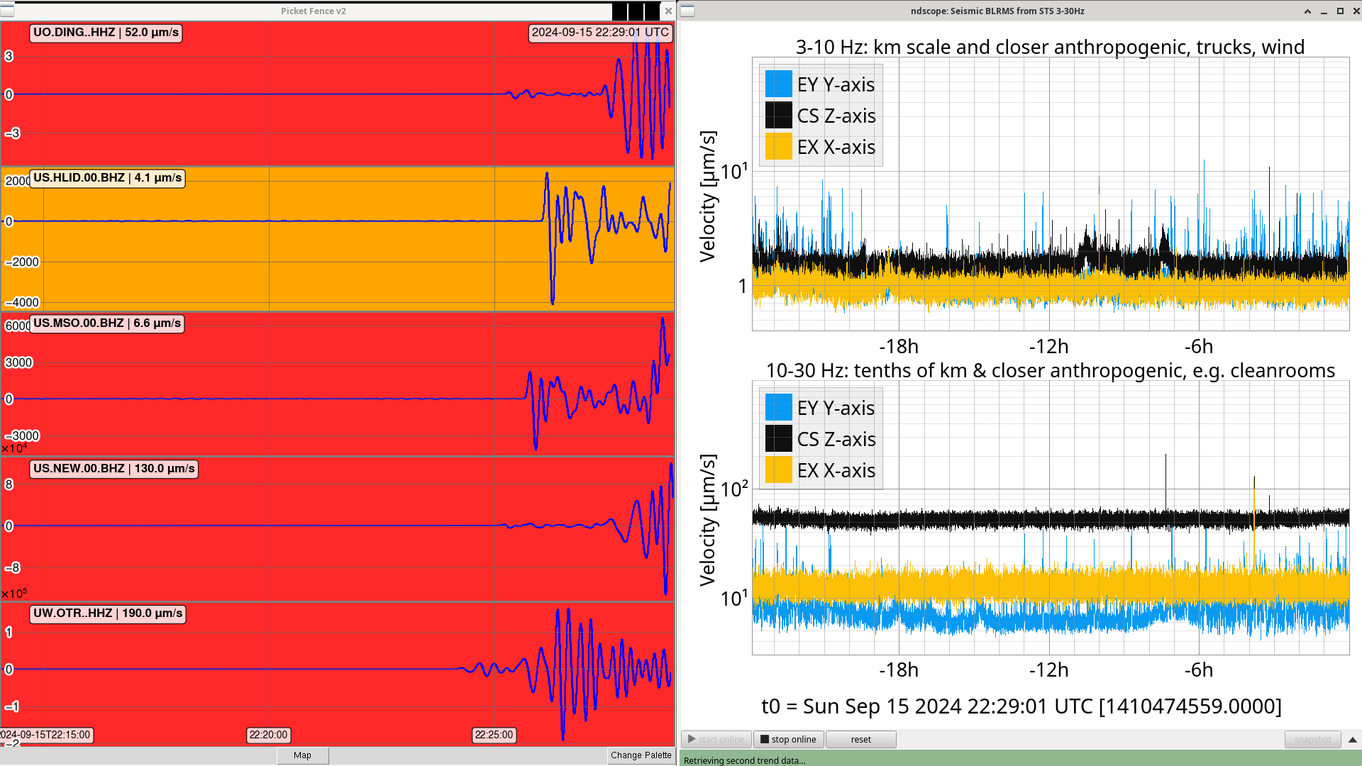
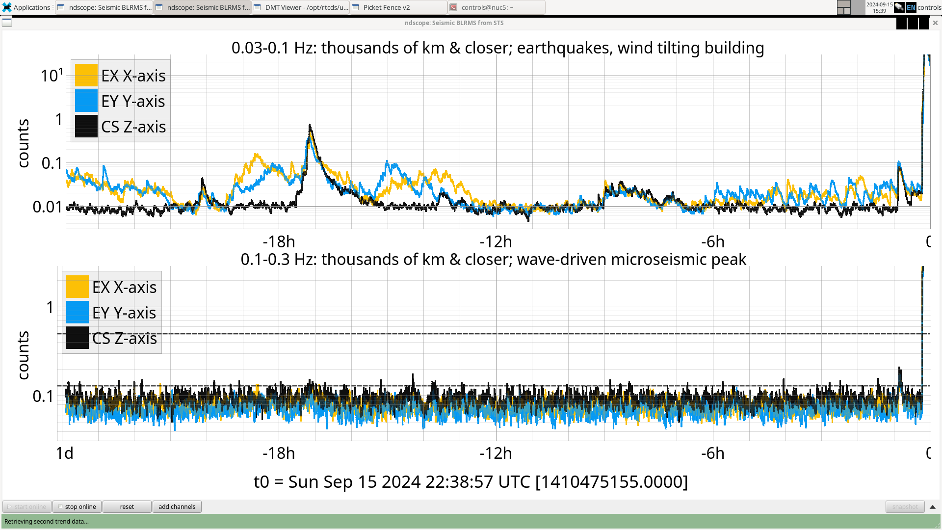
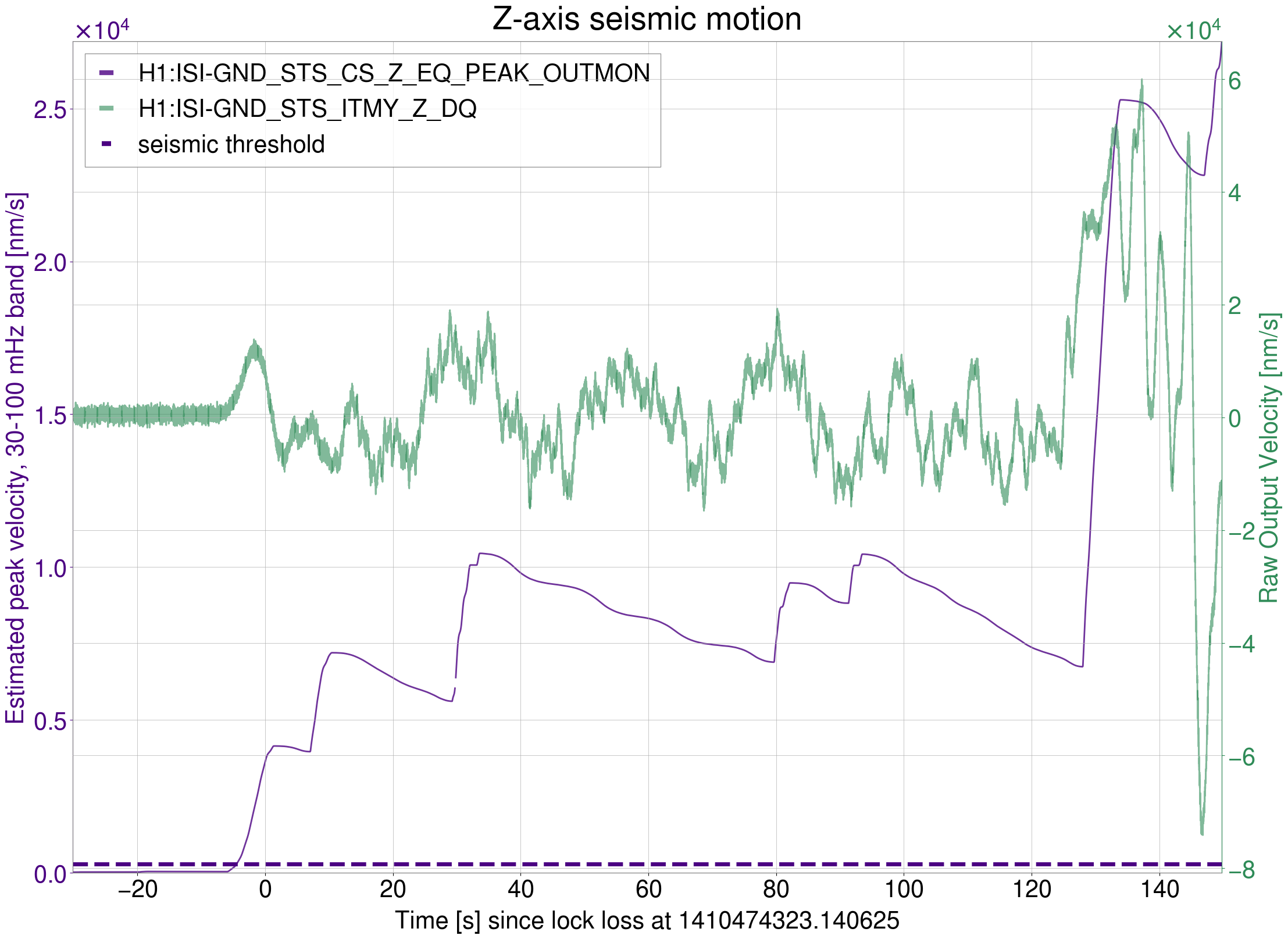
SHIFT SUMMARY: After several EQs overnight ringing up violins, we took time to damp them before commissioning this morning. One lockloss after getting back to observing, followed by a straightforward relock.
- 14:30 - H1 up to OMC_WHITENING damping violins
- 15:54 - Reached NLN, starting commissioning
- 18:34 - Started observing, commissioning finished
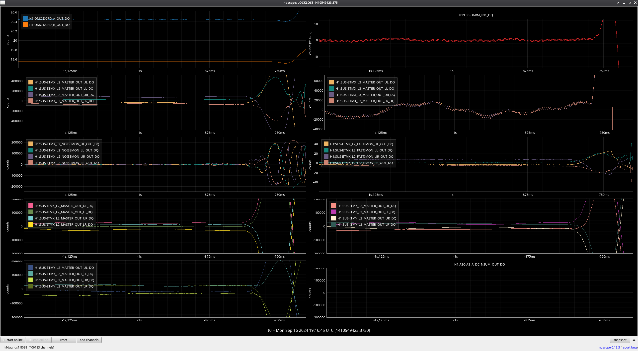
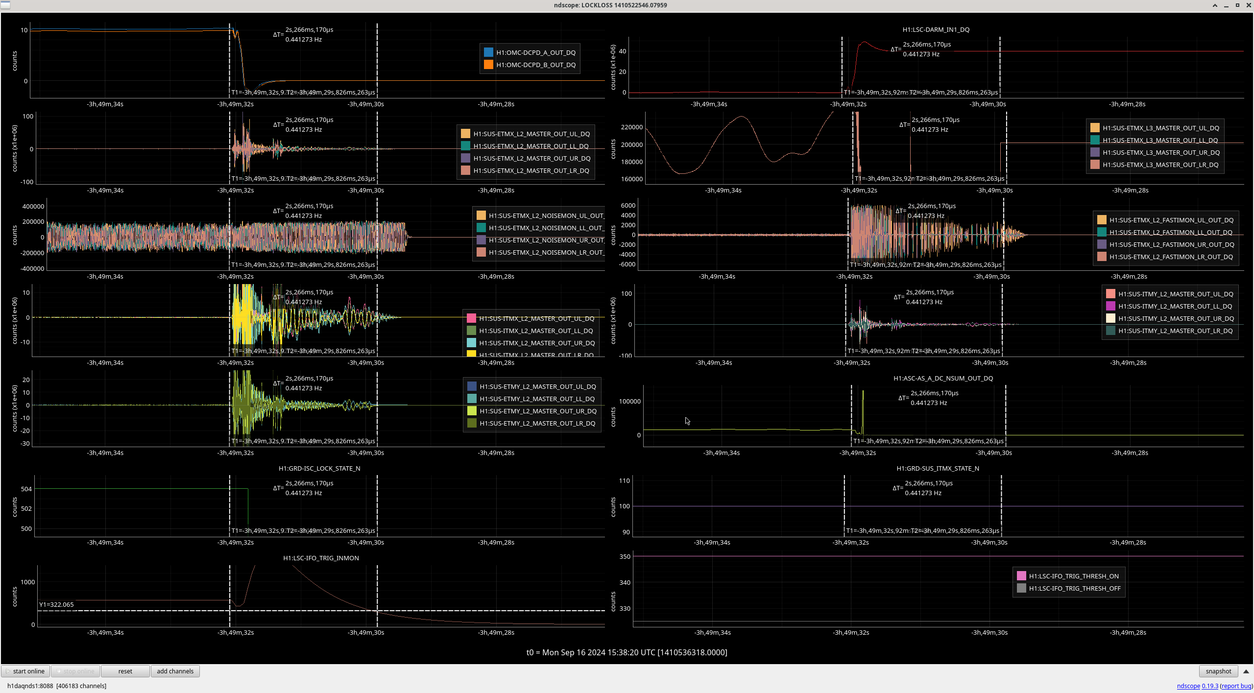
- 19:16 - Lockloss - alog80119
- 20:39 - Observing
H1 has now been locked and observing for almost 3 hours.
LOG:
| Start Time | System | Name | Location | Lazer_Haz | Task | Time End |
|---|---|---|---|---|---|---|
| 23:58 | SAF | H1 | LHO | YES | LVEA is laser HAZARD | Ongoing |
| 15:19 | FAC | Karen | Vac/Opt Labs | n | Technical cleaning | 15:57 |
| 15:42 | PCAL | Tony | PCal Lab | Local | Testing | 16:05 |
| 15:57 | FAC | Karen | MY | n | Technical cleaning | 17:31 |
| 16:28 | FAC | Kim | MX | n | Technical cleaning | 17:12 |
| 19:10 | TCS | Camilla | Opt Lab | n | Grabbing parts | 19:31 |
| 20:04 | PCAL | Tony | PCal Lab | n | Packing equipment | 21:59 |
| 21:06 | TCS | Camilla | Opt Lab | n | Packing equipment | 21:36 |
| 22:42 | PEM | Sam, Genevieve | MER | n | Checking HVAC tube | 22:49 |