ryan.short@LIGO.ORG - posted 16:30, Friday 13 September 2024 (80083)
Ops Day Shift Summary
TITLE: 09/13 Day Shift: 1430-2330 UTC (0730-1630 PST), all times posted in UTC
STATE of H1: Lock Acquisition
INCOMING OPERATOR: Oli
SHIFT SUMMARY: Short lock stretches today for some reason. Fortunately, at least relocking has been mostly straightforward.
- 14:30 - H1 locked and observing for 6 hours
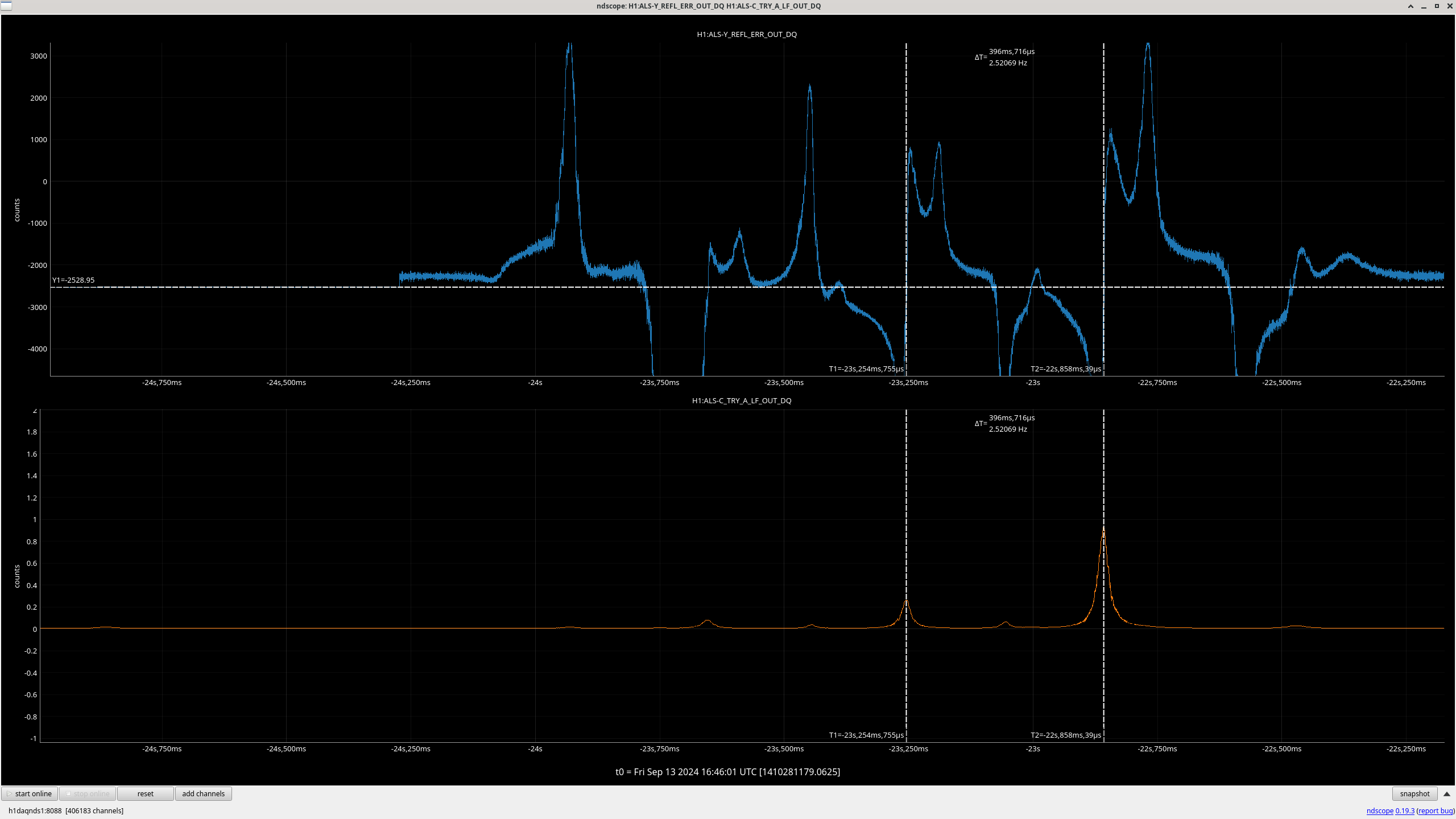
- 16:36 - Lockloss - alog80075
- Taking some time for ALS commissioning
- 18:29 - Observing
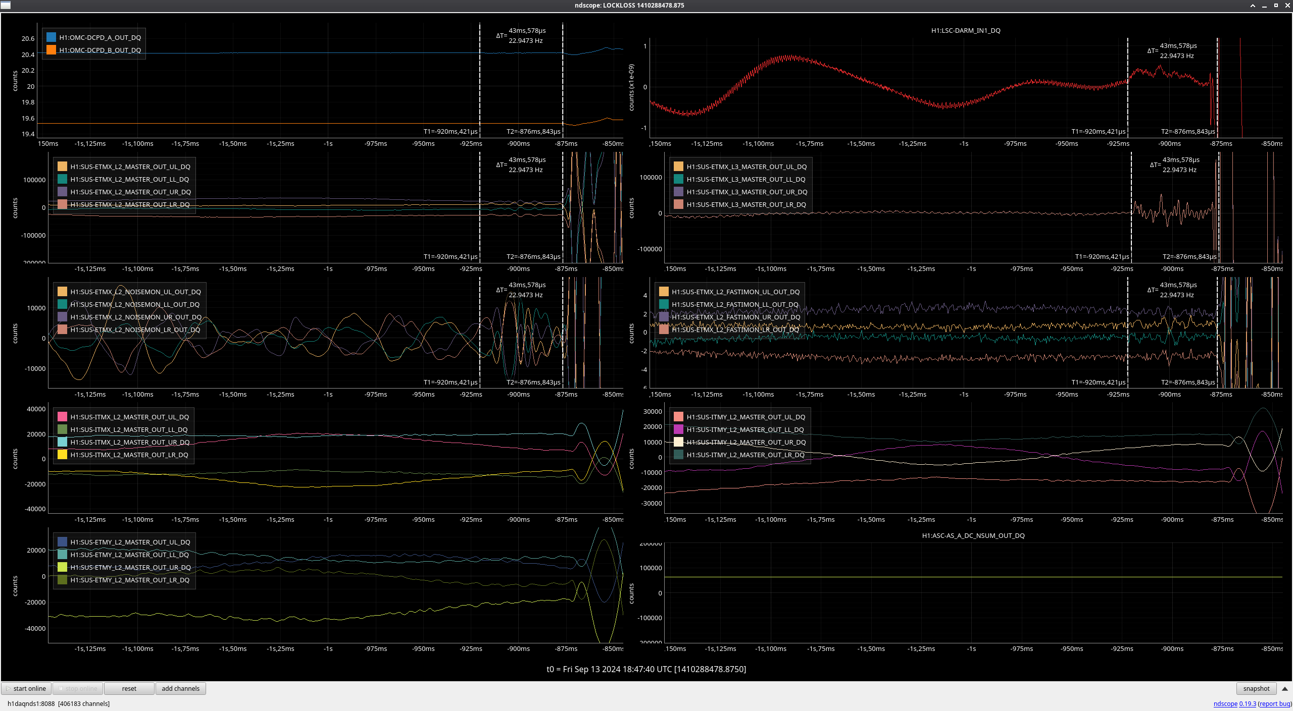
- 18:47 - Lockloss - alog80079
- 19:35 - Lockloss during TRANSITION_FROM_ETMX
- 20:42 - Observing
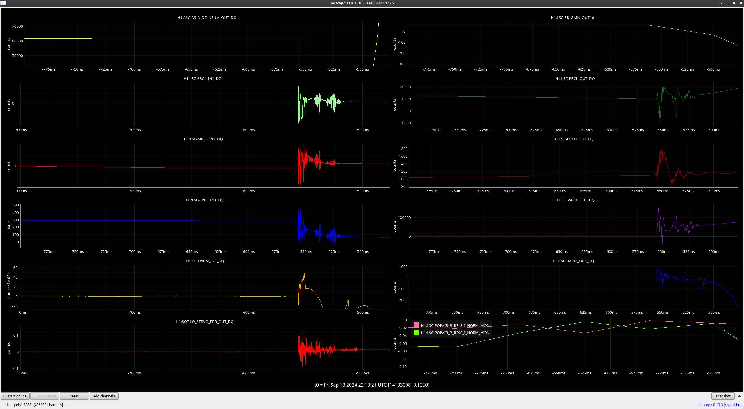
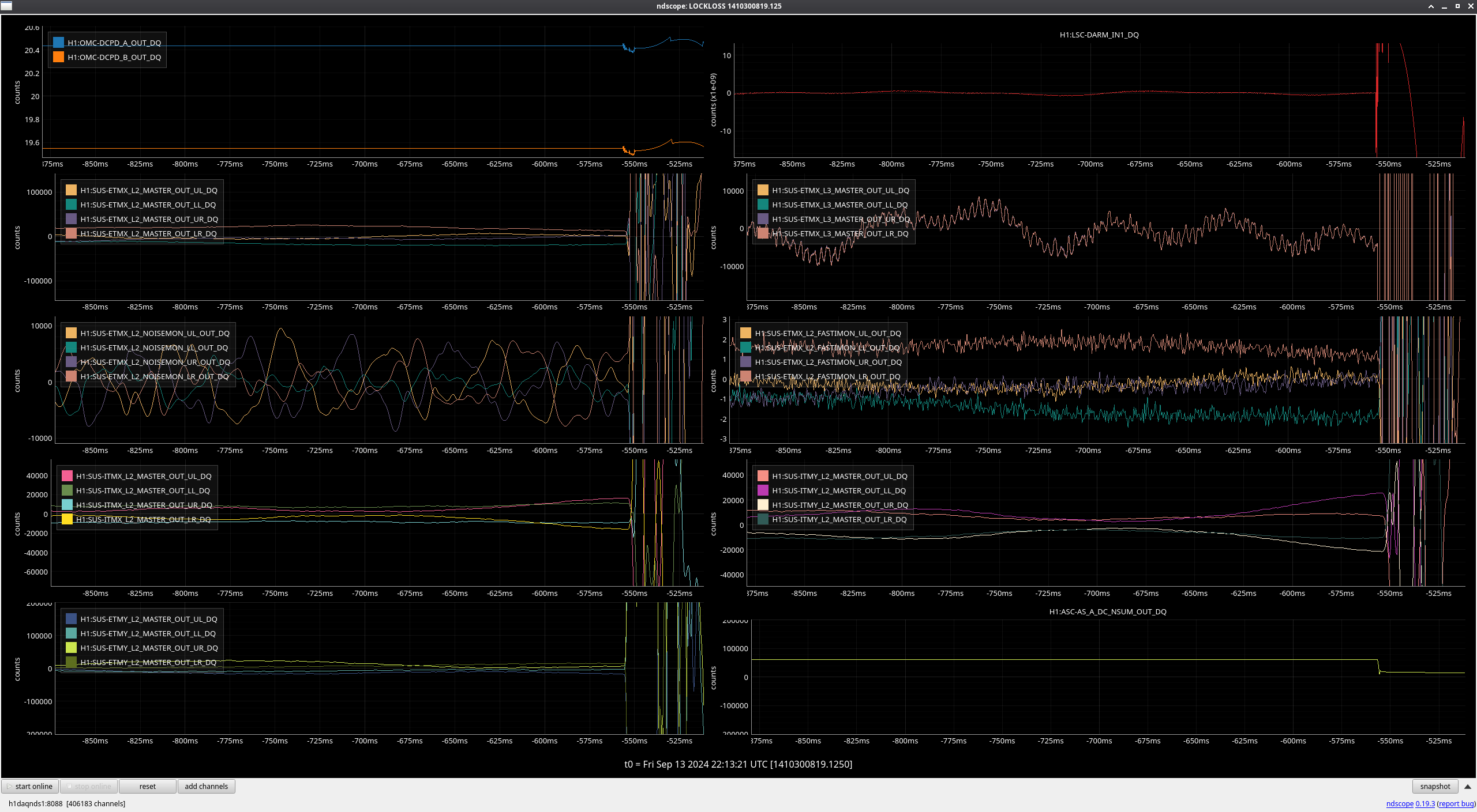
- 22:13 - Lockloss - alog80082
H1 is currently relocking, so far up to TRANSITION_FROM_ETMX.
LOG:
| Start Time | System | Name | Location | Lazer_Haz | Task | Time End |
|---|---|---|---|---|---|---|
| 23:58 | SAF | H1 | LHO | YES | LVEA is laser HAZARD | 18:24 |
| 15:26 | PCAL | Tony, Karen | PCal Lab | Local | Technical cleaning | 16:36 |
| 16:05 | TCS | Camilla | Opt Lab | n | Packing parts | 16:49 |
| 16:42 | VAC | Travis | MX | n | Check nitrogen dewar | 17:12 |
| 17:16 | TCS | Camilla | Optics Lab | n | Packing Parts | 18:16 |
| 18:49 | PCAL | Tony | PCal Lab | Local | Testing | 19:27 |
| 21:12 | PCAL | Tony | PCal Lab | Local | Testing | 21:16 |
| 22:53 | TCS | Camilla | Opt Lab | n | Parts cleanup | 23:18 |