[Sheila, TJ, Ryan S, Elenna]
Here we go!
Ryan S began by running the dither scripts. The ITM and TMS dither scripts worked well, the ETM dither scripts did NOT. Note for future: do not run ETM dither scripts.
ALS X and Y locked well, X was faster than Y as usual. Beatnotes look good!
Input Align successful.
Sheila and I checked SR3 oplevs, and noticed while pitch was very similar to July 12th, pre-vent locking, the yaw oplev had moved by about 20 microrad. We checked that the sliders are about the same. Note: SR2 had to be moved significantly in yaw to find the beam at AS. We spoke to Jim and TJ; they pointed out that HAM5 had been moved (see 79183). Jim moved the HAM5 ISI back by 65 microradians, and this recovered the SR3 yaw oplev alignment to match pre-vent. Note for everyone: 65 micrad of HAM5 ISI motion compared to about 20 microrad of SR3 oplev motion. We should figure out this discrepancy!
Since this step fixed the SR3 yaw alignment, Sheila reverted SR2 back to the July alignment using the sliders.
Ryan began moving PRM by hand to get AS_A alignment better- after this PRC align was successful. However, as PRC1 converged, the AS_A_DC_NSUM decreased. The sensor for PRC1 in this step is REFL B. We did not offload this alignment and instead went to DOWN, and then reran the alignment of PRM by hand. Good alignment onto AS_A for PRM does not correspond to a converged PRC1 alignment in the PRC align state right now.
While struggling with MICH Bright align, Sheila realized that the AS centering was likely the problem. We went to down, turned on AS WFS centering, and saw a huge improvement in the signals, indicating that our issue was that the AS signals were no good. MICH Bright align occured quickly after this change. This may also explain the PRC align issue.
Ryan took us back to PRC align. Indeed, the PRC1 alignment signal converged while maximizing the AS A NSUM. We ran PRC align offloaded this time.
Ryan ran SR2 align successfully.
Sheila had to do a big move of SRM to find the fringing, otherwise, no issues with SRC align. (-577 urad yaw, +300 urad in pitch compared to early July slider positions)
We then paused so Camilla and TJ could realign the AS air camera on the floor.
***********
Lock failure at DRMI ASC- SRC ASC is probably no good, the PRMI ASC ran well. Sheila changed the flag so only MICH ASC runs for DRMI.
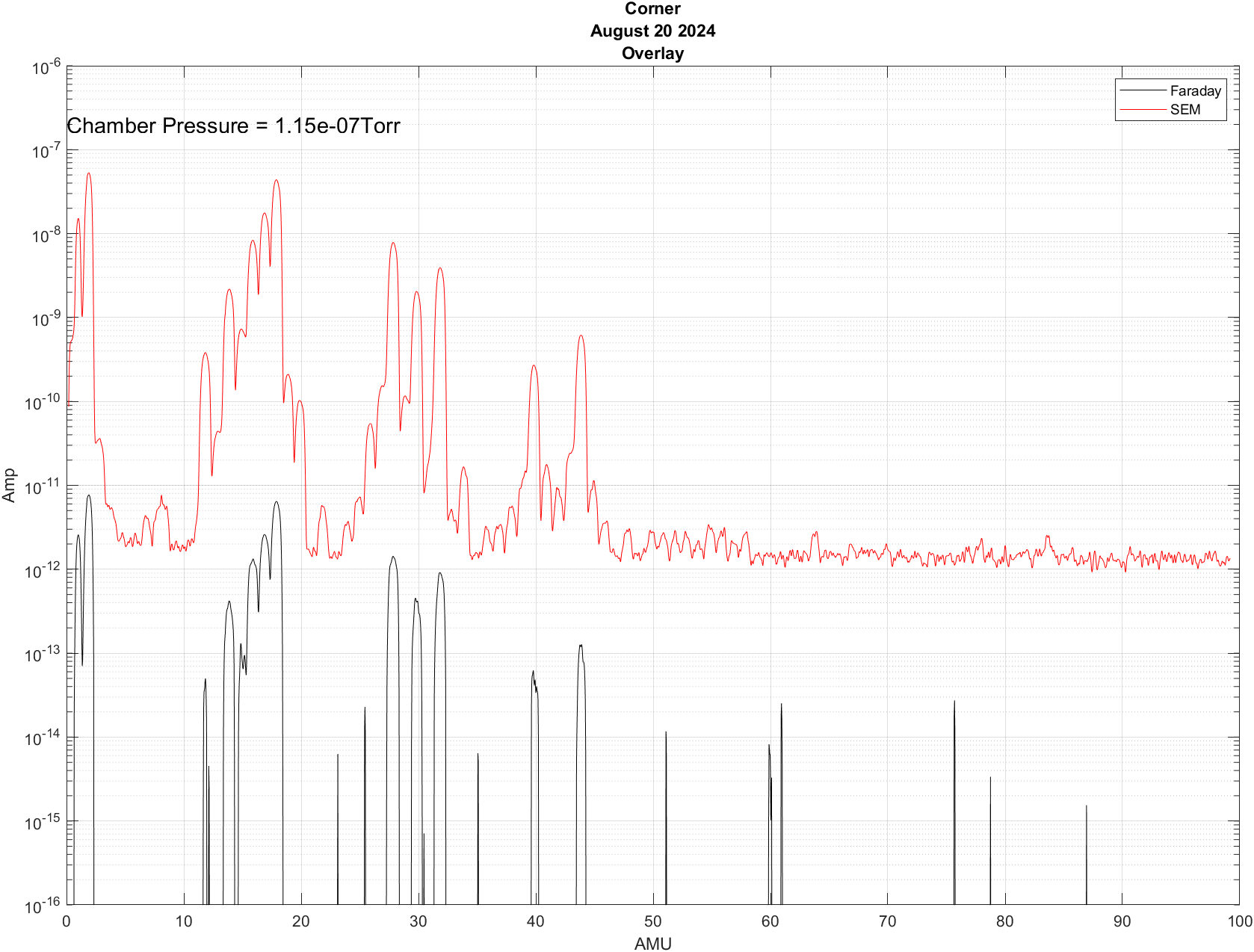
Next lock attempt failed at "resonance". Sheila checked the PRG based on the REFL dip and arm transmission, and it is between 48 and 54 just before lockloss (34% off resonance and 1230 arm transmission, see 62110)
Next lockloss towards the end of "engage asc for full ifo". Hard to tell the cause, but the corner alignment decayed as the various loops engaged.
At the next lock attempt, we stepped engage ASC by hand. All ASC is fine to engage except SRC ASC. Both the SRC1 and SRC2 error signals are far off, and it appears that they are not converging properly to maximize the buildups. This is extra confusing given that SRC2 actuates both SRM and SR2 (using AS_C), however even SRC1 is not very good (SRM actuation with AS RF72). We left the SRC ASC off and engaged the soft loops. By moving SRM and SR2 by hand we can keep the buildups good, but the ASC error signals are still bad.
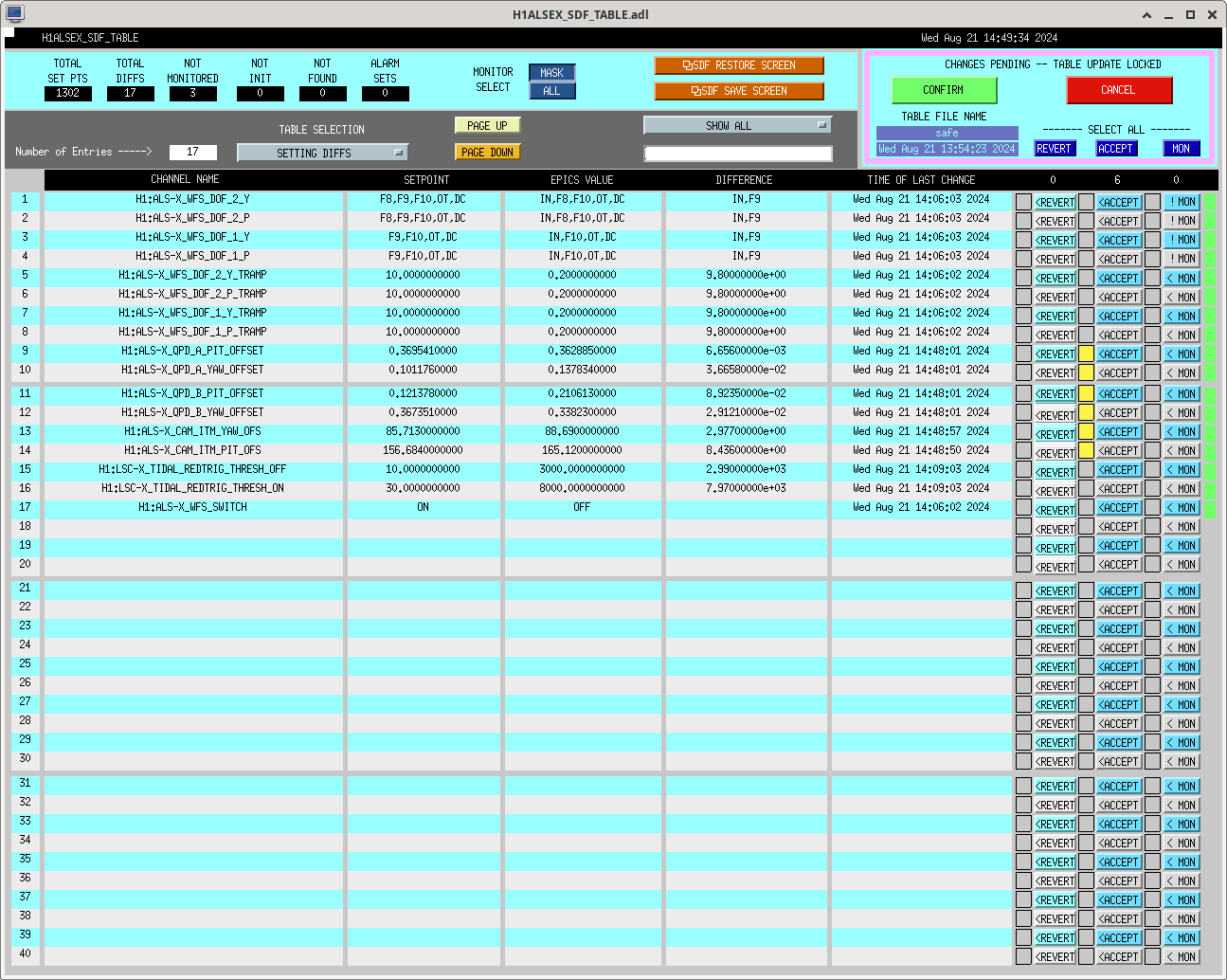
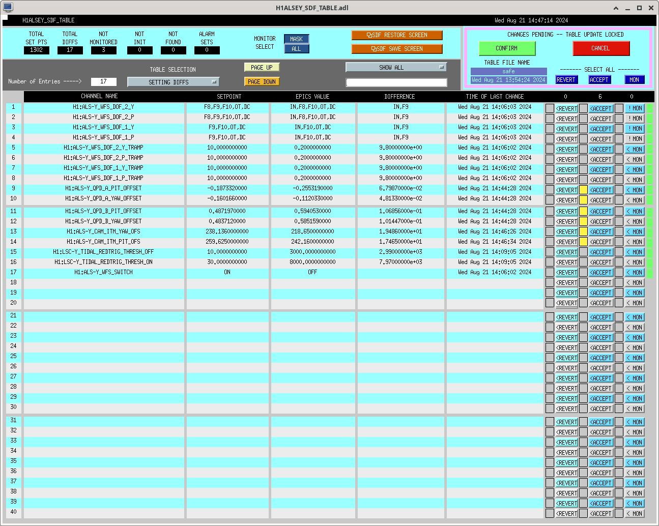
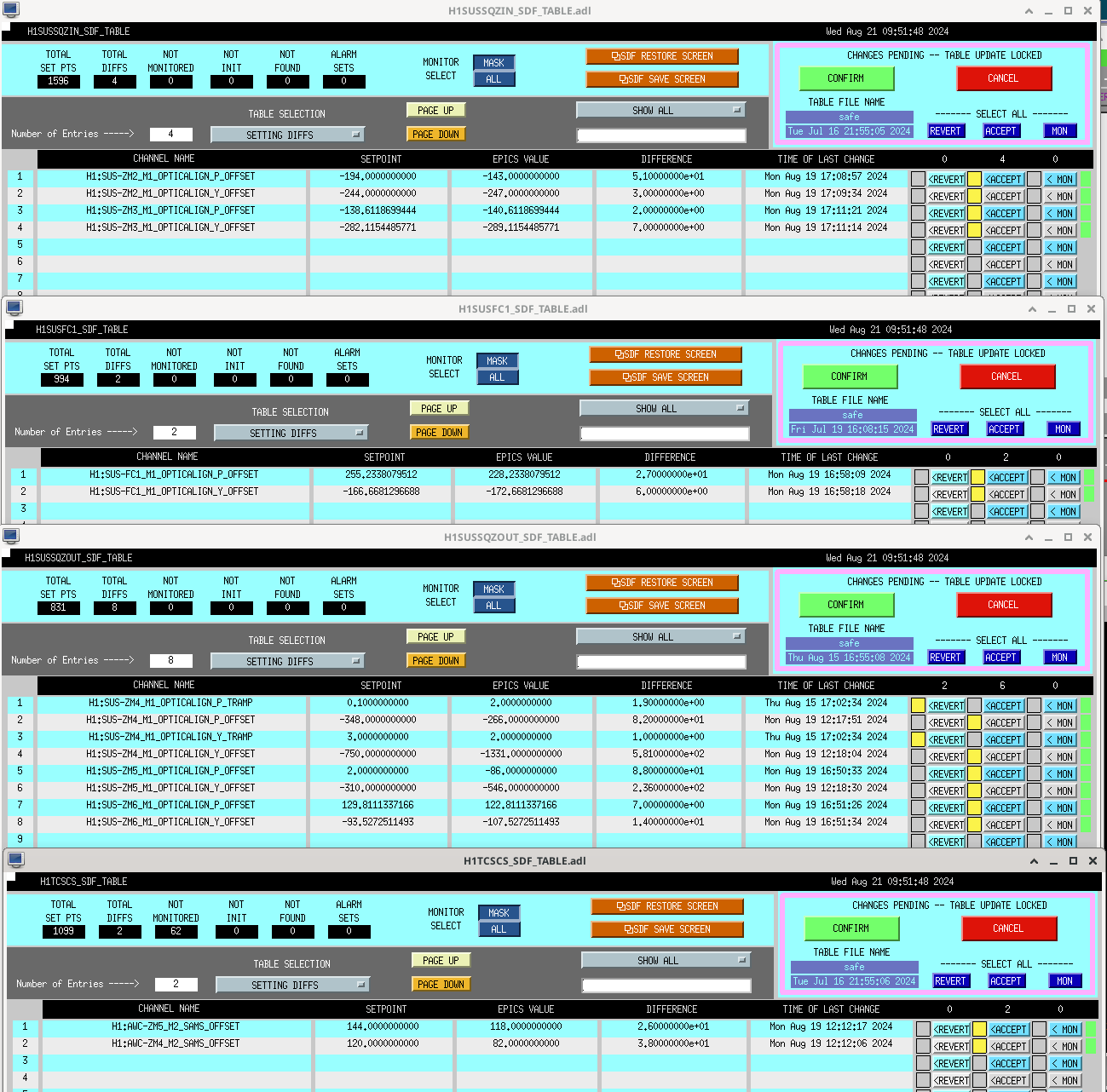
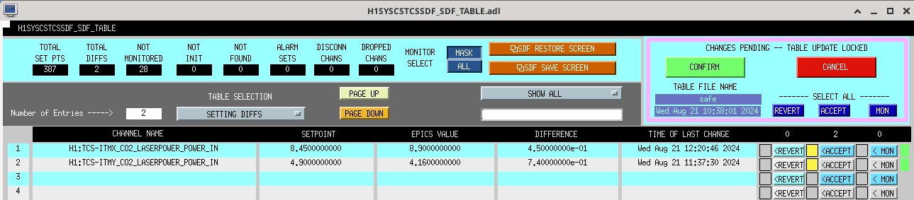
After the soft loops converged, Sheila reset the green references so our alignment is saved. SDF screenshot attached.
We still don't know what to do about SRC ASC, but we have decided to go to DC readout and try damping some violins while we think. DARM offset is on, and we have made it to prep DC readout transition.