Camilla, Oli
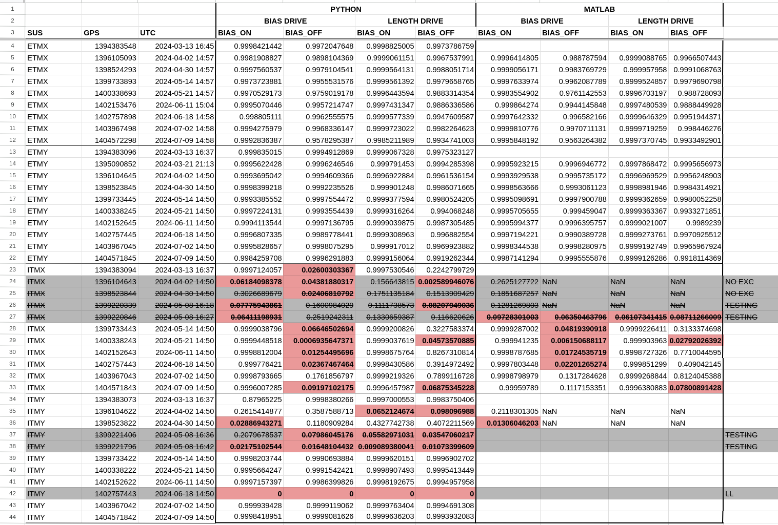
We looked into the weird results we were seeing in the ITMX In-Lock SUS charge measurements. The coherence when the bias is on for both the bias and length drives is always good, but the coherences are bad (usually below 0.09) for both bias and length drives when the excitations run with the bias off.
I compared the differences in the coherence value outputs in the python script versus the matlab script(screenshot), and although the values are calculated slightly differently and are not exactly the same, they are resonably close enough that we can say that there is not an issue with how we are calculating the coherences.
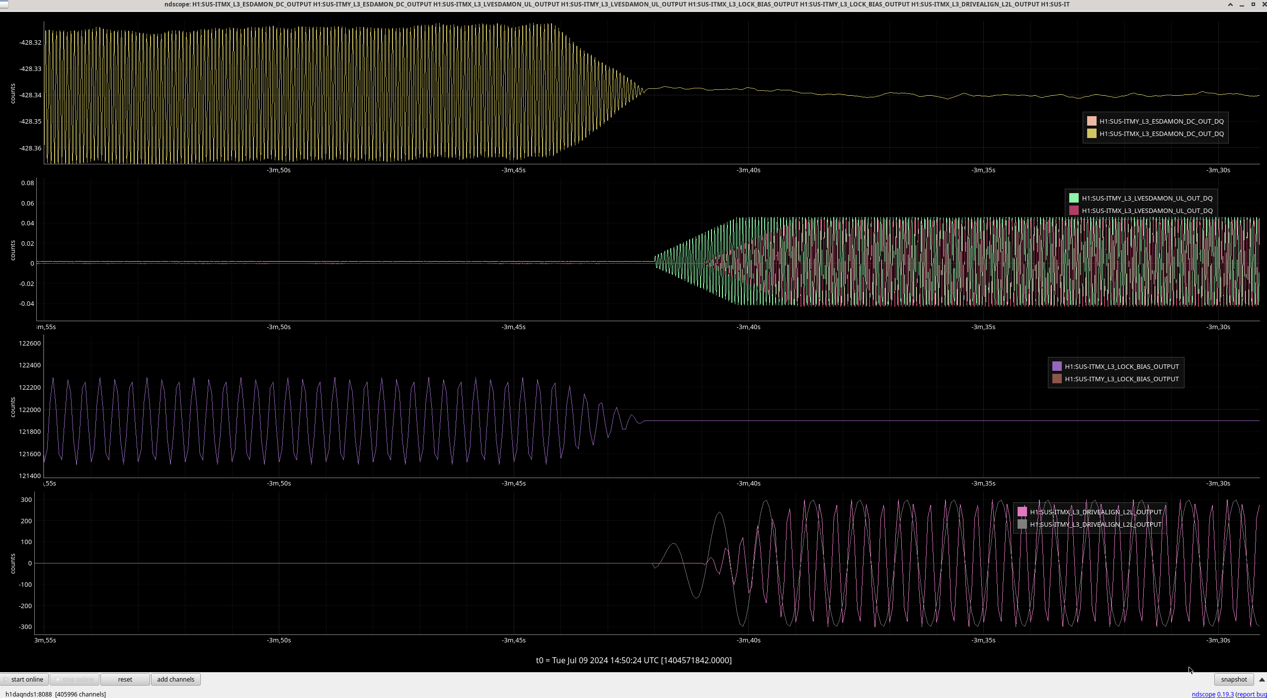
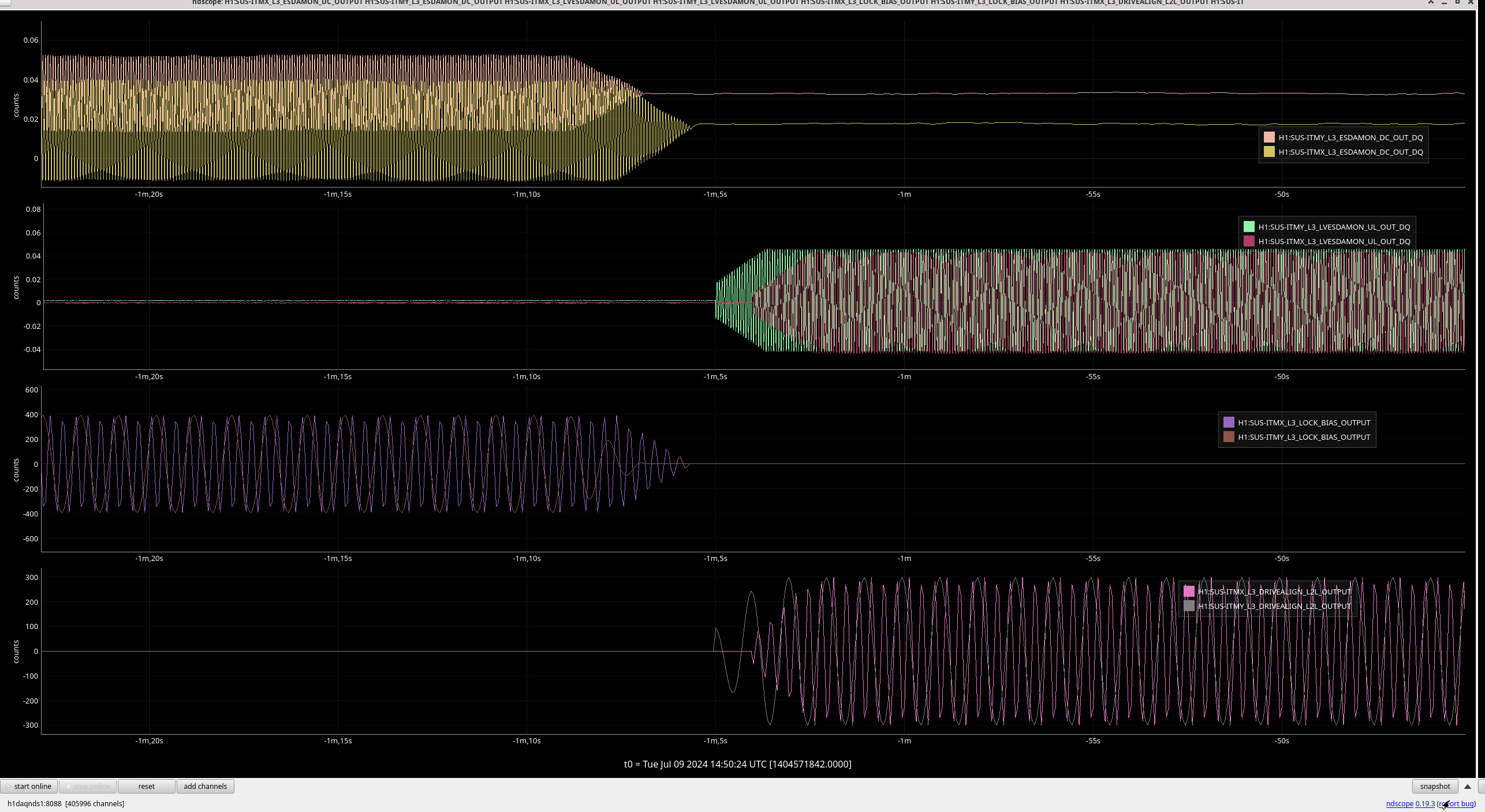
Next, we used ndscope to look at the latest excitations and measurements from July 09th (ndscope-bais on, ndscope-bias off). Plotting L3_LOCK_BIAS_OUTPUT, L3_DRIVEALIGN_L2L_OUTPUT, L3_LVESDAMON_UL_OUT_DQ, and L3_ESDAMON_DC_OUT_DQ for both ITMX and ITMY, if there was an issue with the excitations not going through, we would expect to see nothing on the ESDAMON and LVESDAMON channels, but we do see them on ITMX.
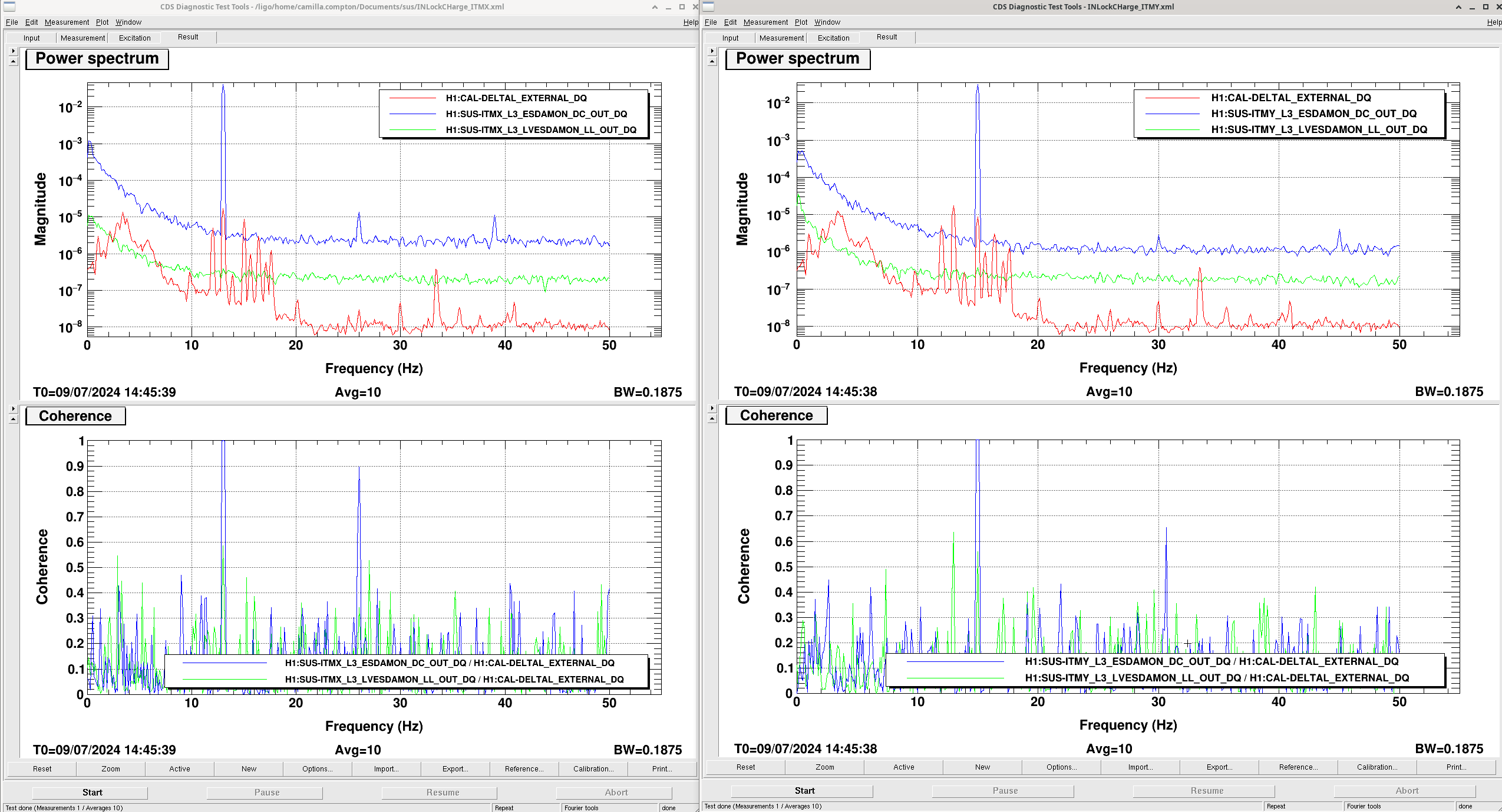
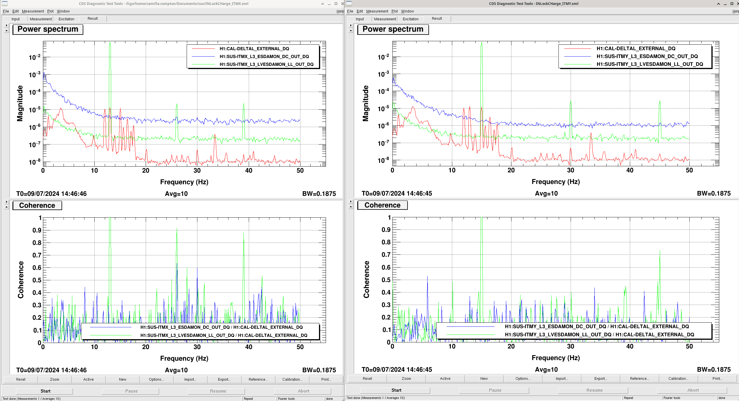
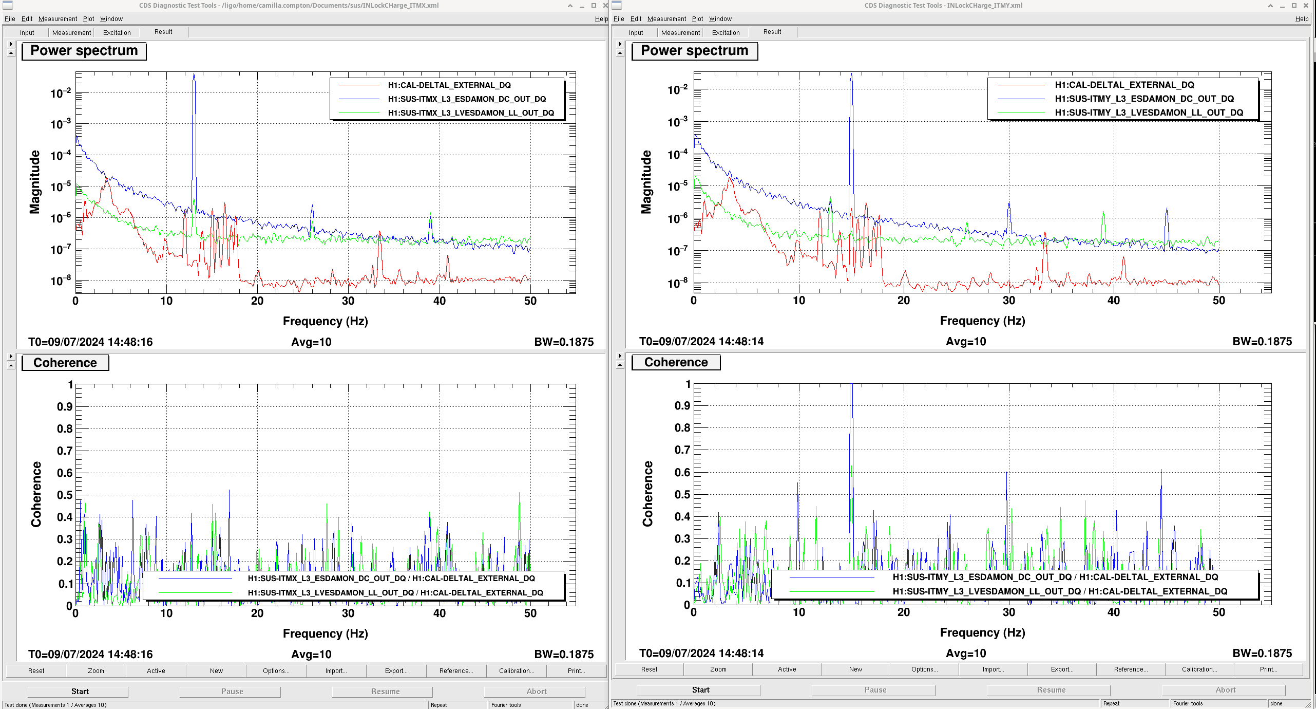
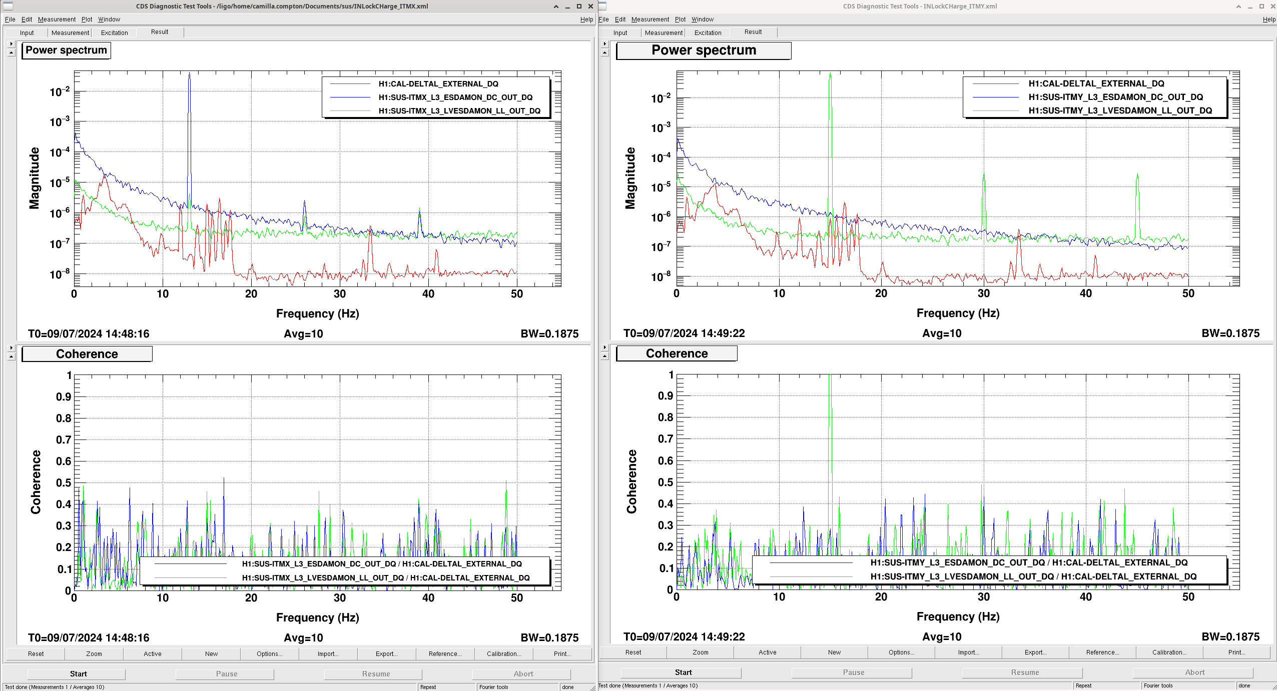
We were still confused as to why we would see the excitations go through the ESDAMON channels but still have such low coherence, so we compared the ITMX measurements to ITMY on dtt for the July 09th measurements looking at how each excitation showed up in DARM and what the coherence was. When the bias was on, both the bias drive and Length drive measurements look as we expect, with the drive in their respective channels, a peak seen in DARM at that frequency, and a coherence of 1 at that frequency(bias_drive_bias_on, length_drive_bias_on). However, in the comparisons with the bias off, we can see the excitations in their channels for both ITMX and ITMY, but while ITMY has the peak in DARM like the bias on measurements, ITMX is missing this peak in DARM(bias_drive_bias_off, length_drive_bias_off). The coherence between DARM and the excitation channel is also not 1 on ITMX.
We showed these results to Sheila and she said that these results for ITMX with the bias off make sense if there is no charge built up on the ITM, which would be the first time this has been the case! So there are no issues with the excitations or script thankfully.
We will be making changes to the analysis script to still run the analysis even if the coherence is low, and will be adding a note explaining what that means.