We were exploring any weird behavior during the locklosses preceding the OFI burns to try and narrow down possible causes, and we recently learned from a scientist experienced with KTP optics that the movement of a high powered beam passing through the KTP could cause damage to the optic, so that created the theory that this could have happened due to earthquakes.
There were a couple of decently-sized earthquakes before the incidents:
April Incident (seismic/LL summary alog79132)
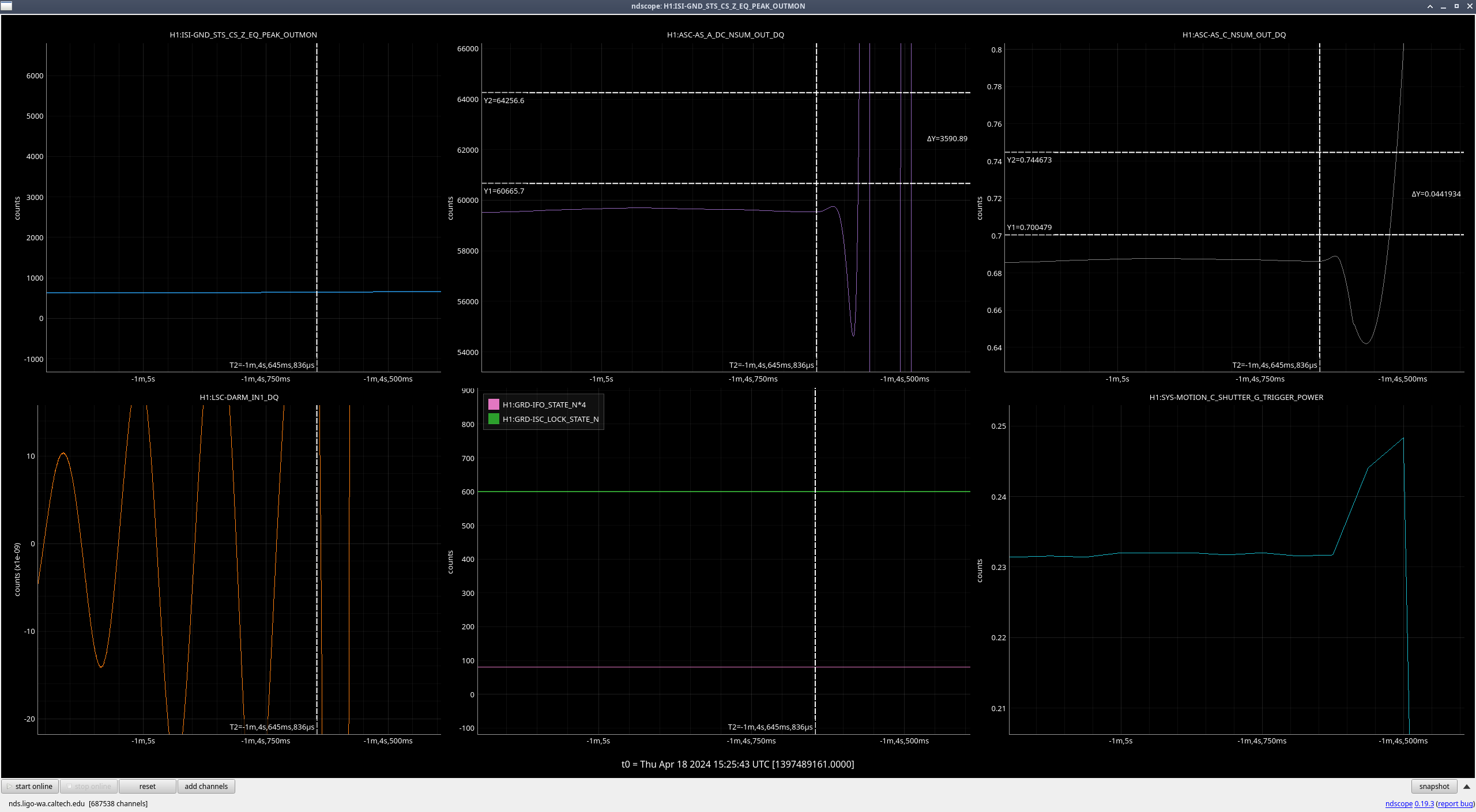
- April 18th - nearby earthquake from Canada - we lost lock from this (lockloss ndscope)
- April 20th - nearby earthquake from Richland - stayed locked
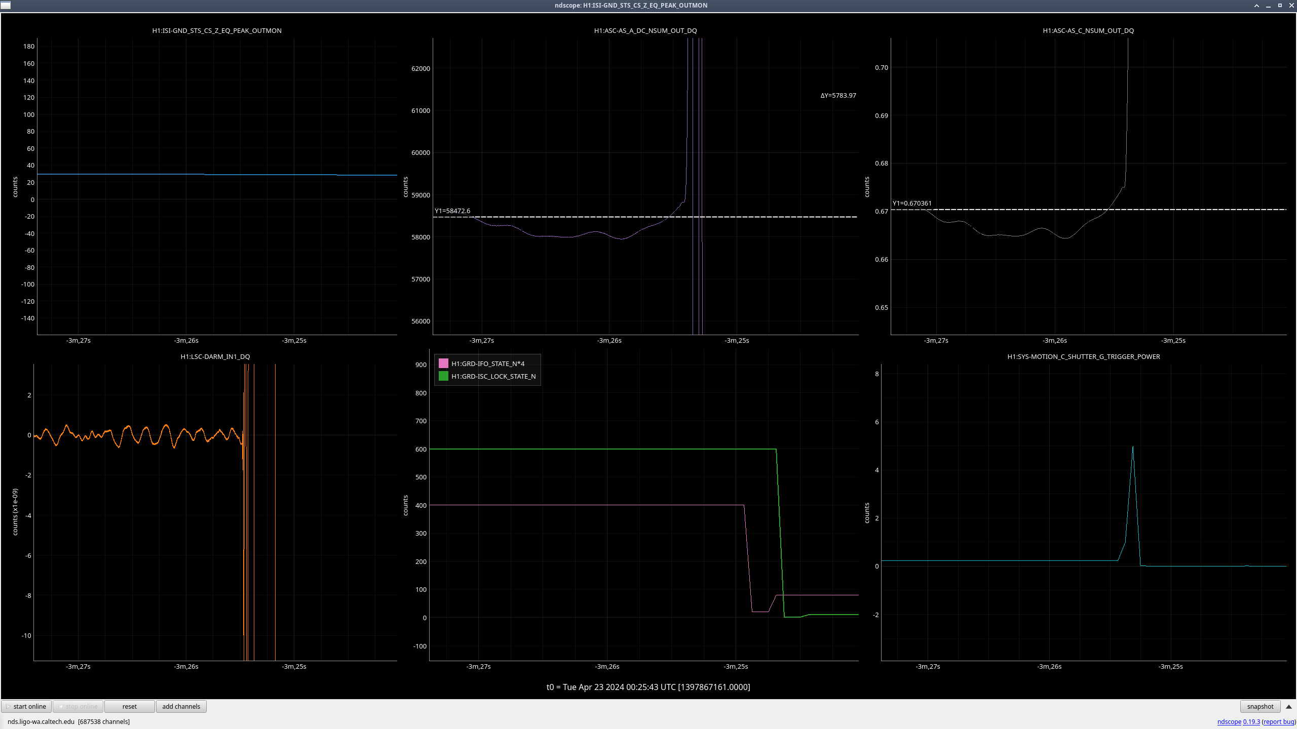
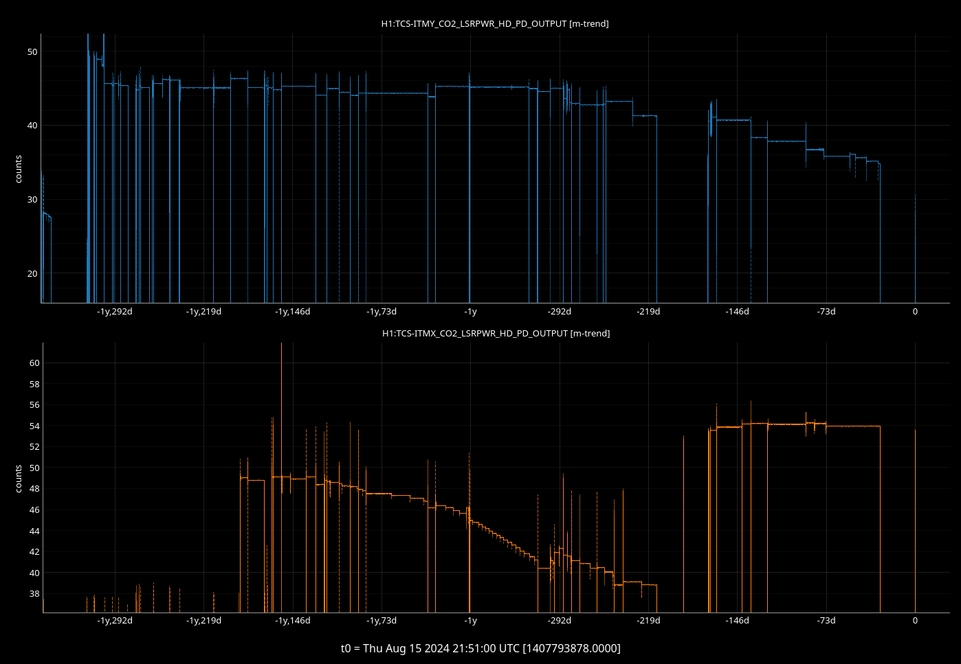
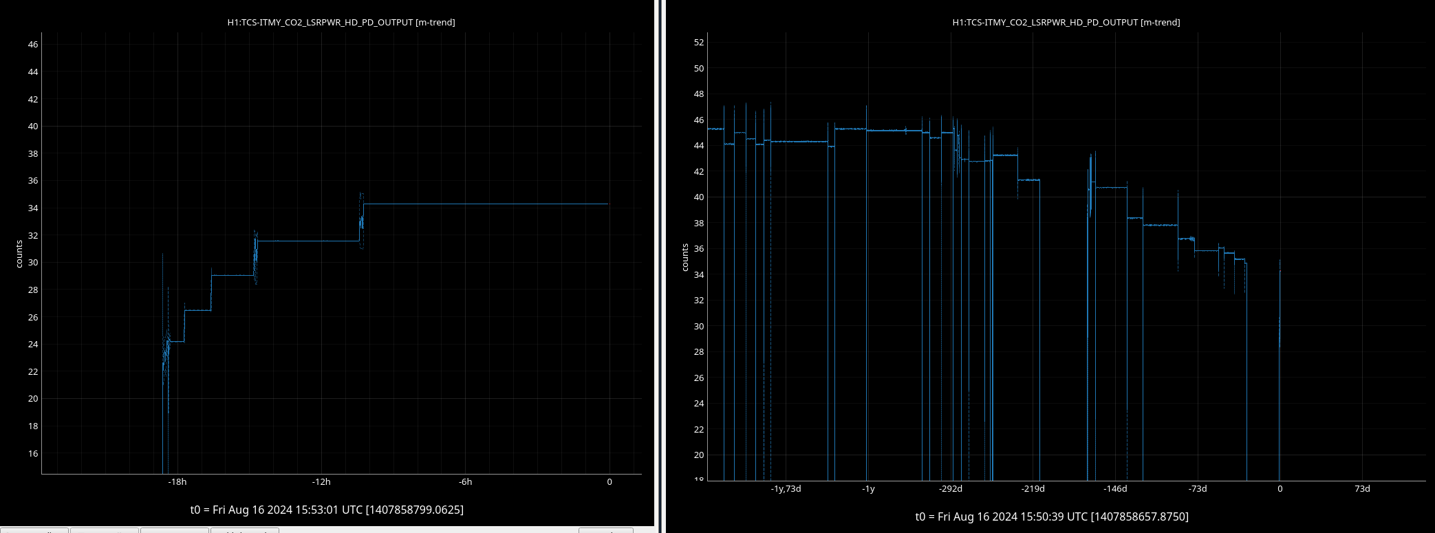
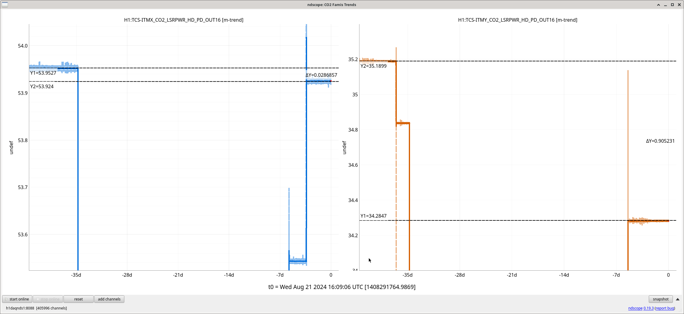
- April 23rd - drop in output power noticed - the lockloss right before this had NOT been caused by an earthquake (previous lockloss ndscope)
July Incident
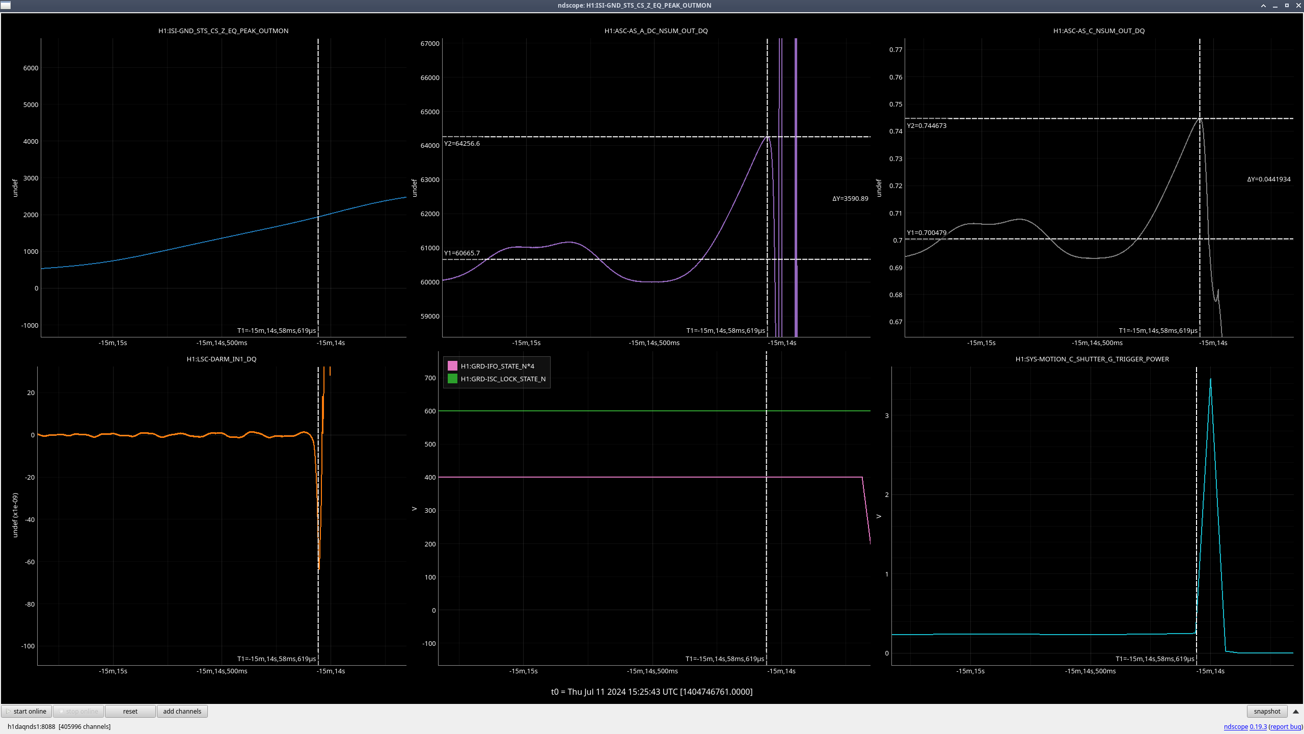
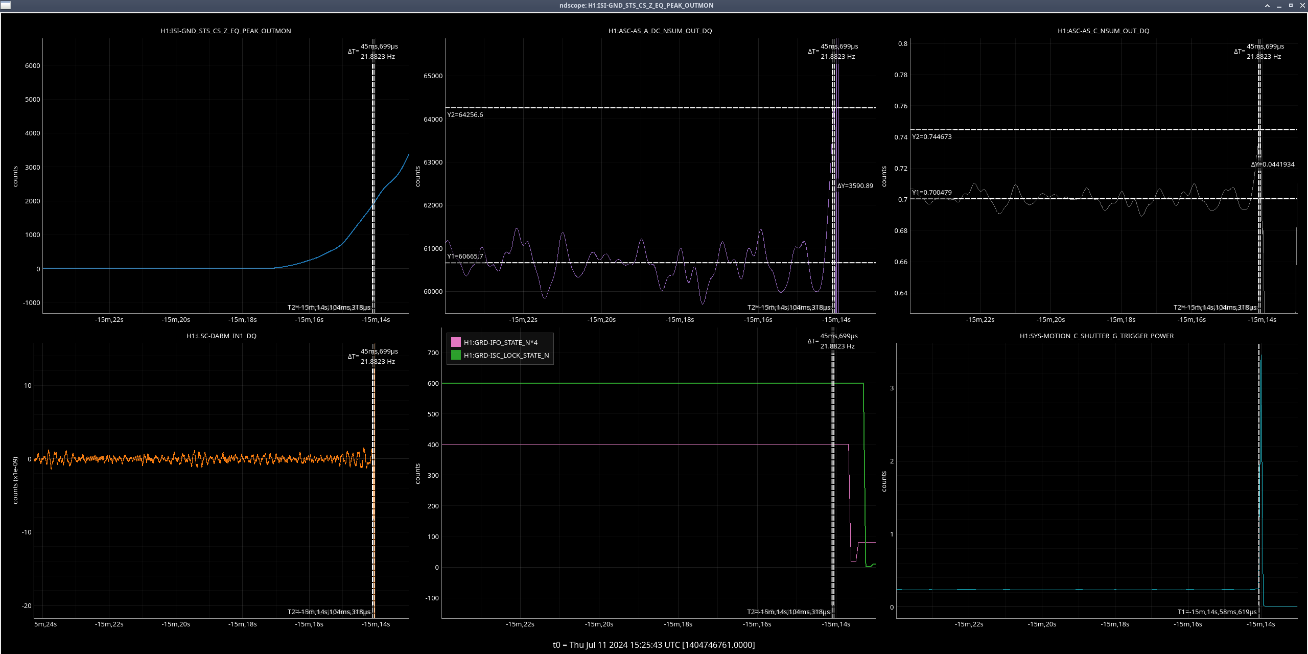
- July 11th - nearby earthquake from Canada (alog79023) (lockloss ndscope, zoomed out lockloss ndscope)
- July 12th - noticed similarities to the April incident
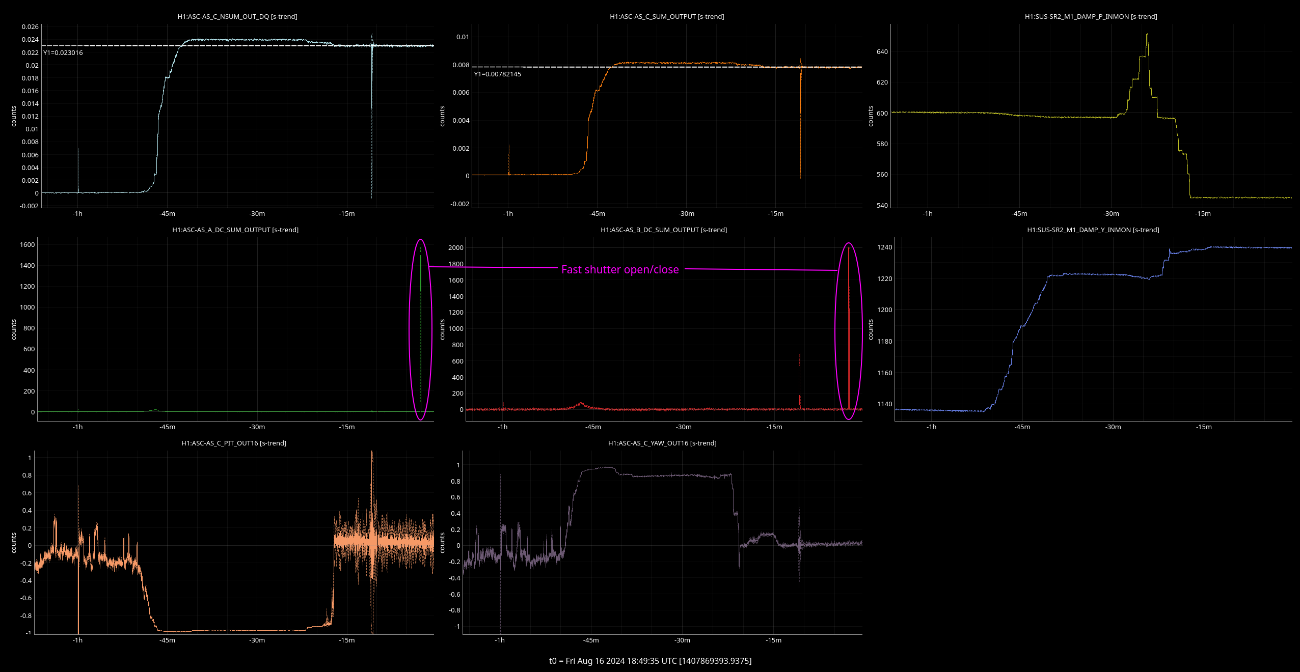
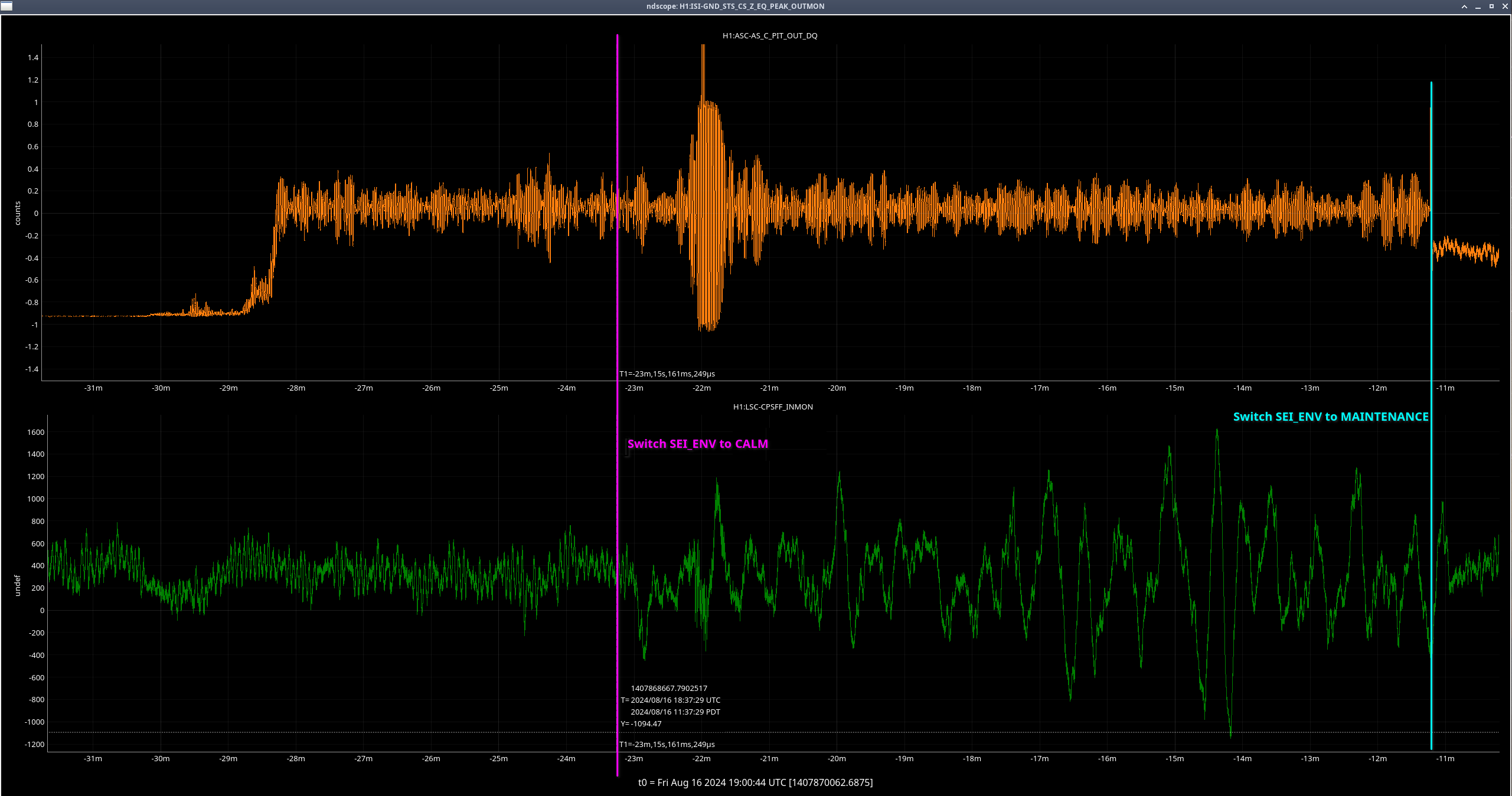
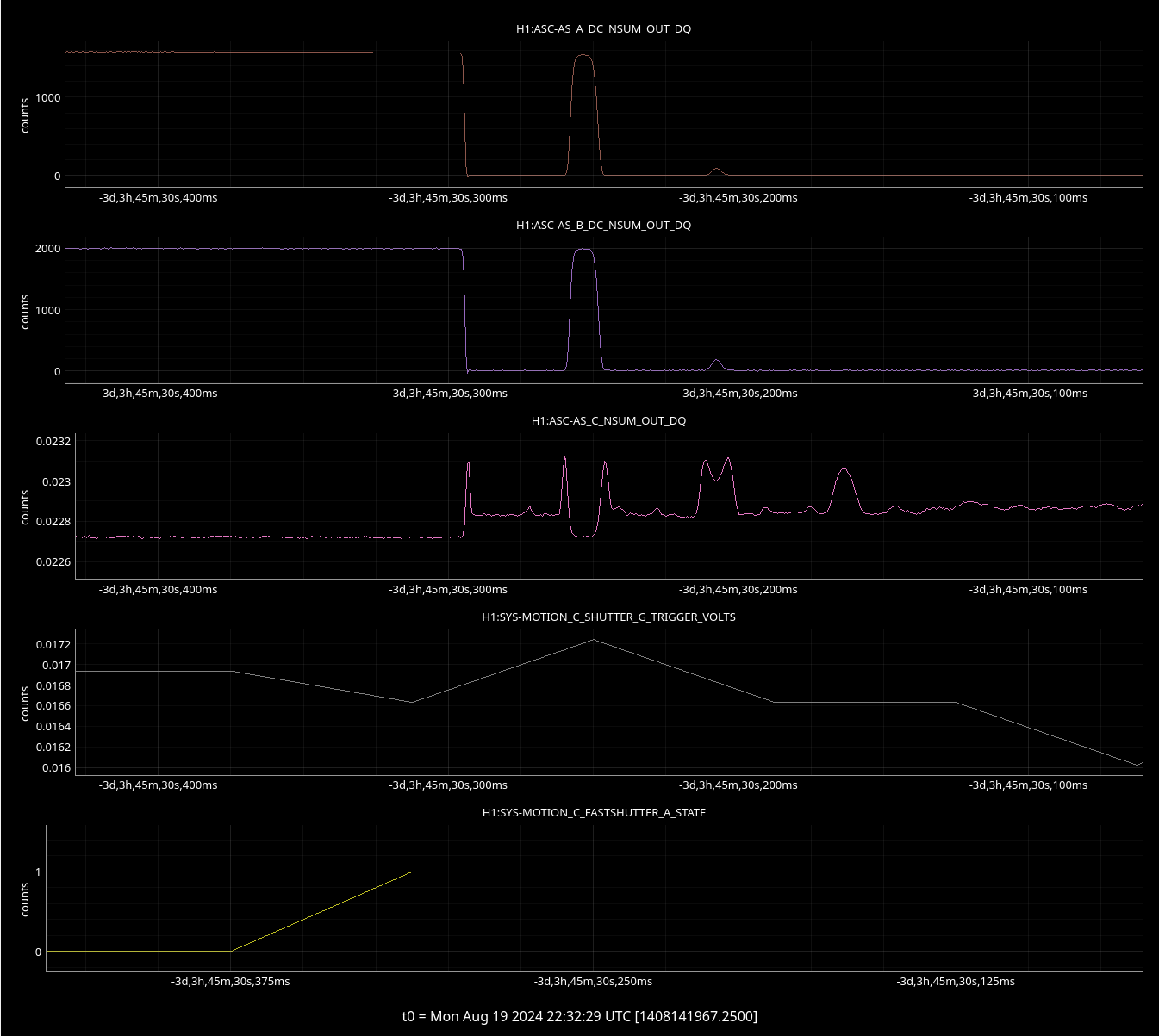
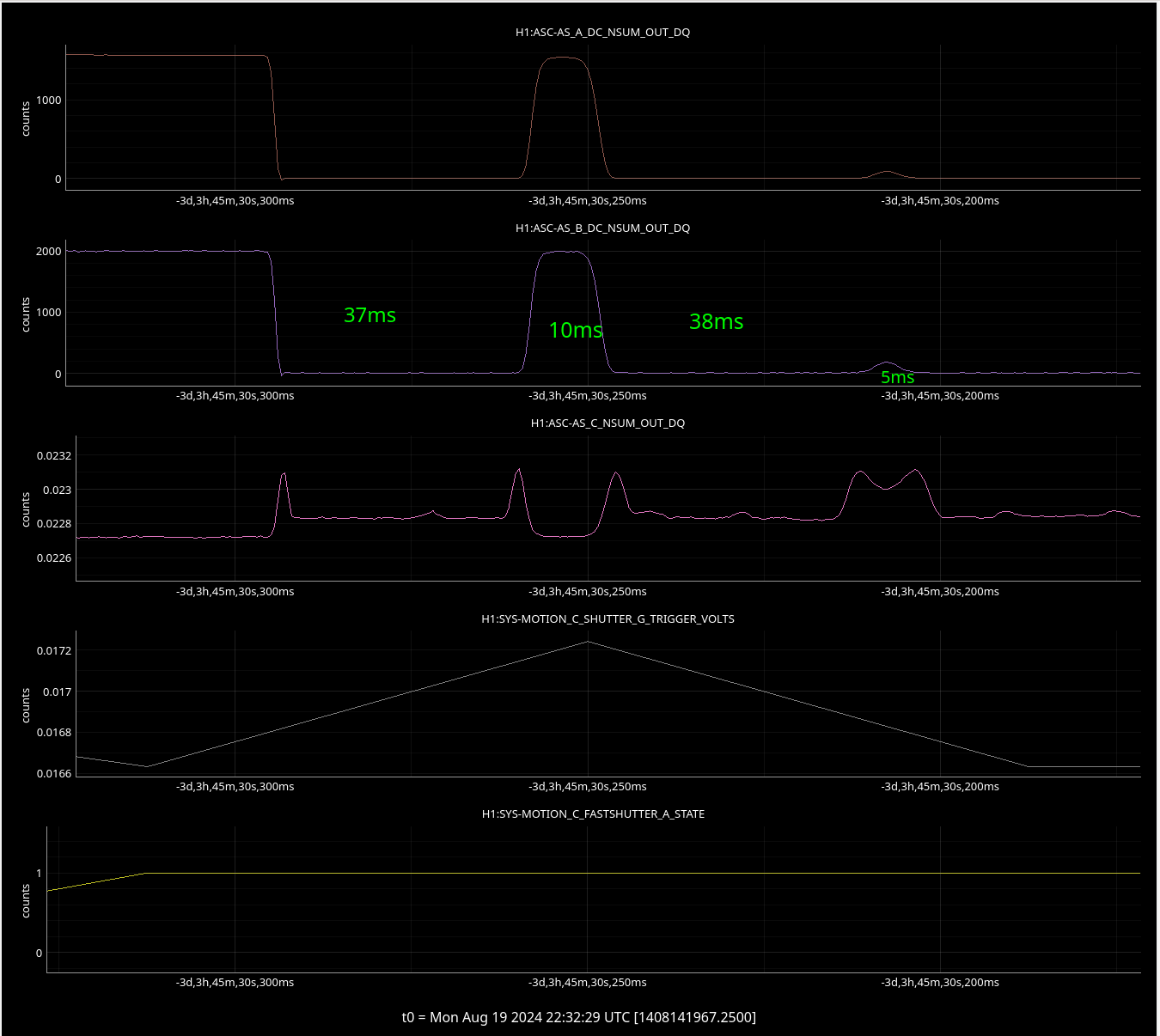
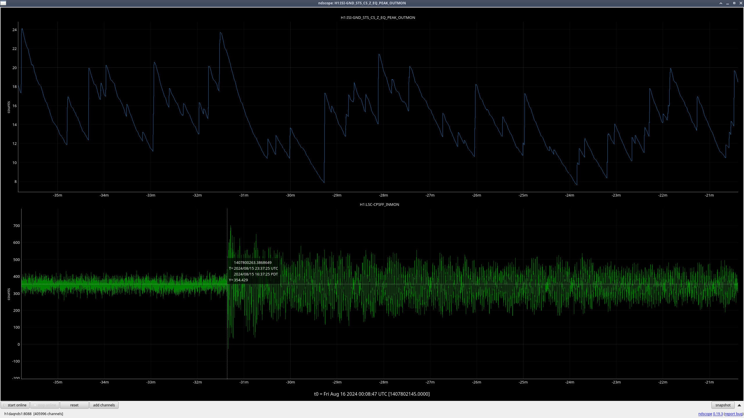
We used ndscope to compare ground motion to DARM, AS_A, AS_C, and the IFO state. In looking over the ndscopes, we don't see anything that would make us think that these earthquakes changed anything in the output arm.
So yes, we did have two decently sized earthquakes (+a local one) before the IFO burns took place, but we also have earthquakes hitting us all the time, many with higher ground velocities. Overall, we did not see anything strange during these earthquake locklosses in the AS_A and AS_C channels that would lead us to think that the earthquakes played a part in the OFI issues.