TITLE: 07/31 Day Shift: 1430-2330 UTC (0730-1630 PST), all times posted in UTC
STATE of H1: Corrective Maintenance
OUTGOING OPERATOR: Oli
CURRENT ENVIRONMENT:
SEI_ENV state: MAINTENANCE
Wind: 10mph Gusts, 6mph 5min avg
Primary useism: 0.01 μm/s
Secondary useism: 0.07 μm/s
QUICK SUMMARY:
H1 is still down for maintenance:
Expected LVEA work today as descriped in the LHO HAM5 V1 Document ES400260:
Measure Isolation - new simpler plan suggestion from LLO (cube between SRM and OFI…) Backup - Need Aux laser in HAM6 as LLO#58791, 58848
If out of spec, adjust TGG crystal location (slots in mount)
Inspect/deal with beam dumps if not done already
Before closeout
Robert in-chamber pictures
Finish testing Fast Shutter, trigger HV
See HAM6 closeout checklist
Rebal OFI
Reinstall OFI Glass shroud
Check AS and WFS, Viewport simulator to check beams coming out
Unlock ISI
Unlock retest SUS/SEI
HAM5 closeout FIRST CONTACT ON SRM 1” WITNESS OPTIC, RH READER
Opportunistic Tasks during vent and pump down work (see Betsy for coordination after July 29th:
ZnSe Window install(s) - would need to vent manifold section(s)
HAM8 in-vac cable troubleshooting
HAM2 SEI controls tune-up
In the afternoon we started placing components on HAM6 and HAM5 to measure the isolation ratio (green components in the attached).
The idea is to use the AUX laser we used for alignment, which will give us ~13mW through the SRM, and retroreflect the beam downstream of the OM1 so the return beam will be about 4mm in diameter at SRM (input beam is ~3mm in diameter, the IFO beam is ~4.4mm, so the return beam will be closer to the IFO beam in size).
Back-propagating return beam was located by inserting a HWP (not in the attached) between TFP and TGG, it's hitting the 50:50 cube and is going in the direction of point B in the first attachment. We blocked the forward propagating beam downstream and confirmed that the return beam went away.
The return beam is supposed to be colinear with the input beam but we haven't made any assessment of that. We will set up a temporary power meter holder at point B (haven't done that today). The HWP is still there in HAM5 but make sure to remove it when you measure the return beam power at point B.
The iris is roughly centered to the forward-propagating beam, but it's not very accurate. It's good enough to block the back-propagating rejected beam that is deflected away into -X direction.
50% of the input beam comes into the direction of point A, and we put a power meter holder there. You still have to adjust the height of the power meter but it's easy to see from the -X door using IR camera.
We misaligned SRM to see if we can locate the SRM reflection of back-propagating return beam in the direction of point A, but couldn't find any. We might try locating it again tomorrow.
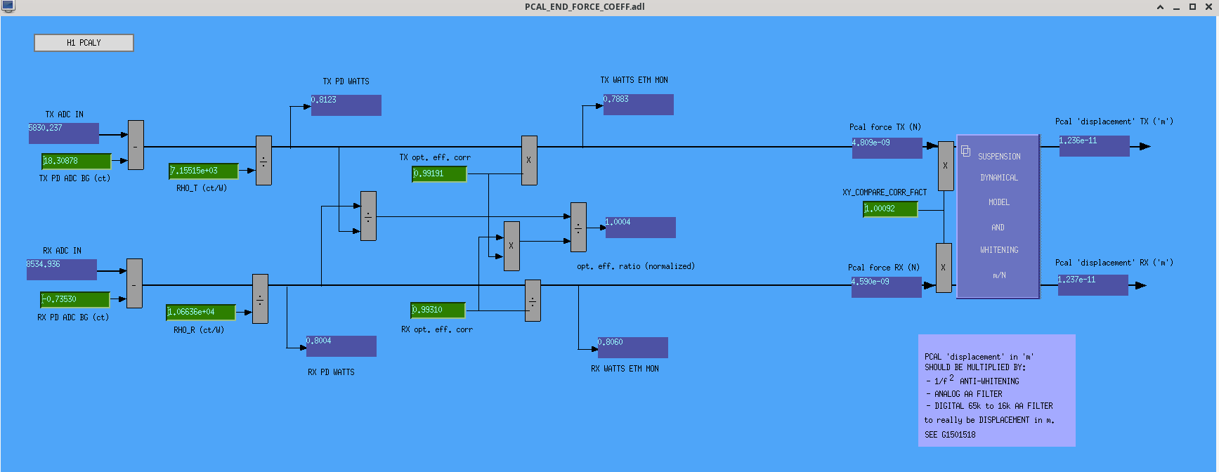
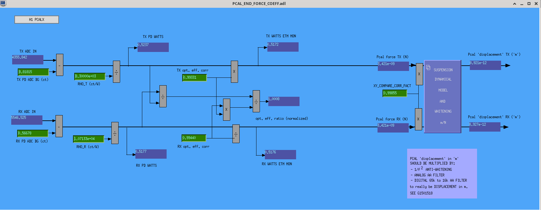
The PCAL team (Tony S. & Cervane G.) went down to End X today, Did an ES measurement. This End Station measurement analysis tool:
python3 generate_measurement_data.py --WS "PS4" --date "2024-06-27" was before we even left the End Station.
This is almost ideal.
There was a little bit of git configuration to do as this was the first evocation of git on that particular laptop after that it worked.
There are a few notes that need to be added to the document though.
To run the Analysis code a date must be entered into to script. This date is the latest measurement date of the working standard you took with you to the End Station.
To find this date, one must go to
/ligo/gitcommon/Calibration/pcal/O4/lab/measurements/
git pull
gedit O4PSparams.yaml and search for PS4. the last date in the PS4 section will git you the date you need.
At a certain point I realized that it is easier to sign in to your own account or just use the following command to switch users within the terminal :
su
Then answer the prompt for credentials.
From there I was able to very easily
git pull
git add
git commit
and git push all from the End Station.
The trend data was then ran from my laptop once I made it back to the Corner Station. This trend data still has the Latex embeded into the python code and will eventually be removed in next iterations.
https://git.ligo.org/Calibration/pcal/-/tree/master/O4/ES/measurements/LHO_EndX/tD20240730?ref_type=heads
Pictures of before and after beam spots look like this due to a beam movement done by Francisco.
TITLE: 07/30 Day Shift: 1430-2330 UTC (0730-1630 PST), all times posted in UTC
STATE of H1: Corrective Maintenance
SHIFT SUMMARY: This morning the fused silica piece for the OFI was installed, and afterwords the LVEA was transitioned to Laser HAZARD for alignment checks and to set up for an isolation measurement.
LOG:
| Start Time | System | Name | Location | Lazer_Haz | Task | Time End |
|---|---|---|---|---|---|---|
| 14:56 | FAC | Karen, Kim | LVEA | n | Technical cleaning | 15:36 |
| 14:59 | FAC | Tyler | MY | n | Checking fire alarm | 15:12 |
| 15:06 | PCAL | Tony | PCAL Lab | YES | Prep for EX measurement | 15:57 |
| 15:19 | VAC | Fil | FCES | n | VAC wiring updates | 16:05 |
| 15:26 | ISC | Camilla, Keita, Sheila | LVEA | n | FS install | 17:23 |
| 15:32 | VAC | Gerardo | LVEA | n | Check on purge air | 15:48 |
| 15:33 | FAC | Kim, Karen, Nelly | FCES | n | Technical cleaning | 16:42 |
| 16:10 | PCAL | Tony, Cervane | EX | YES | PCal measurement | 19:12 |
| 16:27 | FAC | Kim | EX | - | Technical cleaning | 17:36 |
| 16:28 | FAC | Karen | MY | n | Technical cleaning | 17:36 |
| 16:28 | VAC | Travis | LVEA | n | Check on turbopump | 16:42 |
| 16:47 | FAC | Nelly | EY | n | Technical cleaning | 17:36 |
| 17:06 | OPS | Oli | LVEA | YES | Laser HAZARD transition | 17:23 |
| 17:22 | SAF | Laser HAZARD | LVEA | YES | LVEA is Laser HAZARD | Ongoing |
| 17:23 | ISC | Keita, Camilla, Jennie, Sheila | LVEA | YES | FS install and alignment | 19:25 |
| 17:35 | 3IFO | Tyler | MX, MY | n | 3IFO checks | 17:56 |
| 17:53 | OPS | Oli | LVEA | - | Parts delivery | 18:00 |
| 18:36 | SEI | Jim | FCES | n | Checking HAM8 CPSs | 20:59 |
| 19:14 | PCAL | Tony, Cervane | PCal Lab | YES | Putting away equipment | 19:17 |
| 19:45 | FAC | Eric | FCES | n | Air handler work | 21:43 |
| 20:18 | ISC | Sheila, Betsy, Jennie, Keita | LVEA | YES | OFI isolation measurement (Sheila out @ 22:55) | Ongoing |
| 23:02 | PCAL | Tony | PCal Lab | YES | Getting equipment | 23:07 |
Sheila, Keita, Jennie, Camilla
After practicing with the damaged Fused Silica (FS) wedge, Sheila and I installed the new FS wedge. Labeled E1900361 S/N 07 Run# P20-378, 379. We noticed some dust/fiber on the FS after install (didn't inspect before) so Keita wiped with a clean swab. Photo's after cleaning are first and second attachments.
Yesterday 79351 we found indium foil between part (3) and (5) of the FS assembly D2000037 where the (6) screw contacts. Rodica reccommended we add a new piece of indium foil. Third photo attached.
Keita installed the FS holder ot the assembly and we adjusted roll by eye. We installed the assembly onto the OFI. We reinstalled the beamdump bar (never moved dumps on it but wiped them yesterday) and the baffle bar and baffle. Baffle was installed in the same location, touching the double thick beamdump. We then unlocked the OFI and reinstalled the nominal motion limiter screws.
We then transitioned to laser hazard, the retroflection of the aux beam looked good and we checked that SRM was in it's nominal position. No reason to go to SR2.
The beam through the OFI started very (50mm?) low and was hitting the fast shutter. We then adjusted the roll of the FS wedge assembly to correct for any pitch, it was hard to make fine adjustments and tightening the screw moved the beam. It was a little off in yaw. Keita has photos of the beam position.
We repeated yesterday's 79344 throughput power measurements with more laser power:
The rejected beam to SQZ goes through ZM6 baffles, and around the middle of the HAM7 GV.
Sheila then headed to SR2 and checked that the beam was centered in pitch and yaw.
After taking IR photo, the beam position on the iris close to OM1 seems to be off by about ~2.75mm/2 radius from the center of the iris at 45 degrees angle, i.e. it's too low by ~1mm and to the +X direction in YAW by ~1mm. Look at the 1st picture looking at the iris from the direction of HAM5. There's no parralax though its more focused on visible light than IR.
1mm too low and 1mm to +X don't sound like a big deal, once we have the IFO we should be able to change the beam positions on SRM/OFI and SR2 to get back higher and to the -X if necessary. Remember that the iris was set using the beam we believe to reproduce the alignment before the second crator incident, and we have found that the beam was too high on OM1 using that beam. So the beam being too low on the iris could be a good thing. But we'll make sure that we can see the beam on ASC-AS_C.
The 2nd picture shows that the diameter of the iris hole is a tiny bit larger than 2.5mm but smaller than 3mm.
Roll adjustment of the fused silica wedge is not that easy at this level (1mm over maybe 2.5m? distance), a tiny rotation results in big change and loosening/tightening the set screw for the rotation seems to change the deflection. As far as we see the beam on ASC-AS_C we won't adjust the FS wedge further as this won't change the isolation/throughput etc. of the OFI.
Serial number of the original FS wedge is 001 according to Rodica.
From what Camilla wrote above, the new one we've just installed is S/N 007.
Not including the first measurement where the laser power was clearly lower, we calculated with attached:
Transmission: 99.82% with stdev 0.72%
Ratio rejected by TFP: 0.188% with stdev 0.004%
The sum of these is 100.01%, which is within the margin of error.
Tagging for EPO.
Dew point measurement taken this morning read at -43.8 oC. Measurement taken before any activity inside chambers. Soft covers were on HAM5 and HAM6, HAM7 is isolated and a bit pressurized.
Tue Jul 30 08:09:44 2024 INFO: Fill completed in 9min 40secs
FAMIS 21010
PMC REFL hasn't been rising as much over the past week, but it certainly still is. Everything else looks fairly nominal.
Workstations were updated and rebooted. This was an OS packages update. Conda packages were not updated.
Betsy, Camilla, Sheila, Jennie W, Keita, Robert
21:30 UTC Camilla and Betsy figuring out new way to lock diwn the OFI.
22:05 Placing peak sheet to shield ofi while they unscrew bars from FS assembly.
22:40 Took mount with bar and beam dumps still attached out of HAM5. One of the bolts for the bar was stuck in the mount so they unscrewed it chamber side.
22:42 Sheila dis-assembled FS wedge mount
Sheila left at 23:00 UTC
Camilla and Betsy taking photos and videos of damage and wiping beam dumps and mounts.
We found indium foil in the top screw hole of the mount which would sit on top of the wedge.
23:00 UTC Robert came to take photos between HAM5 and 4 from outside chamber.
23:14 Keita joined.
Lots of discussion about what to do about mounts as there was lots of the black coating in the screw holes and so Betsy and I washed the holes on the FS mount with isopropanol and she tapped the holes again.
00:10 Camilla and I put beam dumps back onto OFI.
Mount and old FS wedge covered up chamberside and cover back on.
Everyone out by 00:15 UTC.
Camilla to add pics.
Some more details and photos.
Betsy and I locked the OFI suspension the correct way, following 3.1.2, 3.3.1 and 4.2.1 of E1300056-v4. We locked the -X-Y corner and then moved the small baffle to lock the -X+Y corner. Will need to reattach this baffle when done. Left +X cornered unlocked as one had osem in the way and the suspension felt very secure with only 2 corners. Photos attached: first and second.
Photos attached of:
Videos are in the OFI googledrive:
There is photos of the FS assmebly after cleaning with the new FS installed in 79363
Almost galled one of the 1/4-20 bolts which held the Beam Dump mount bar onto the FS wedge mount during removal. Once the entire subassy was out of the chamber we worked it with isopropyl in the bolt thread joint and managed to get it out. Once totally disassembled, the 4 mount holes retapped with obvious material removal. Cleaned with isopropyl flushes.
Pictures of debris on the now removed FS wedge optic attached. We didn't attempt to remove the debris, but instead put it right in to one of the suspended optic containers to stow/ship with the other optics to CIT in case a coating measurement needs to be made and compared to specs on it as well. The debris was removed from its metal mount so I don't see why First contact wouldn't remove it from this optic surface as well.
Tagging for EPO.
Noticed that GV5 had hard closed on Saturday at 19:59 utc time, no human intervention. It appears as if the instrument air pressure left for soft close GV5 was enough to hard close it. According to PEM instruments near GV5 made lots of noise, see attached plot, accelerometer and microphone data.
I checked the dial on the gauge to measure the instrument air at GV5, and indeed there was only about 10 psi, this value is within the "usual" pressure used for soft clossing pneumatic gate valves and per procedure.
No interaction is required at this moment from the vacuum team.
Tagging ISC, since sensitive equipment is hanging near this gate valve, like cameras and OpLevs.
I converted this microphone DQ signal to an audio wav file. The microphone saturates at +/-32768 for a fraction of a second, but you can hear the echo fade away after this.
Here is the accelerometer as a wav audio:
(new file added at 13:52, orig file was created using the incorrect frequency of 16kHz, this is actually a 8kHz channel)
The ITMY Oplev (aligned at the time) didn't see this hard close, plot attached.
Remember GV1 is closed, this makes ITMY Oplev blind, Sum on trend above is very small.
After discussing with Jenne this morning, I have flipped the sign of the ETMX ESD lock bias voltage from -450V to +410V to reduce the charge build up in the optic. I will keep this settings for a week or two and measure the charge on the optic. If the charge gets reduced, then will continue with this until we are ready for locking the IFO - will revert the settings to nominal values at that point. Attached below is a trend of the lock bias offset and ESDAMON_DC_OUT, which shows the changes I have made today.
I have made some adjustments to the L3 HV mon for ETMX after having some email discussions with Jenne. The latest settings is opposite sign and value (of high voltage) of what we have during Observing run (and not Down state - which is what I did earlier).
The first screenshot I have attached below shows the sign and value (positive 123V), when we were at Observing.
The second screenshot shows latest settings, i.e. negative 123V 450V (full negative). I will revert this once we go back to locking the IFO.
Keita, Sheila
Summary: We chipped the spare KTP crystal this morning, and this afternoon installed the back up spare that Rodica had shipped. We've adjusted the roll, and the pitch angle seems better than the crystal that we removed. So this should be ready to go into the chamber first thing Monday morning. We have many photos from today, which will be attached and annotated to this alog later.
Following on From Jason's alog 79319
With this placement of the damaged KTP in it's assembly, where the assembly is bolted perpendictular to the beam path, and a wave plate to mix the polarizatoins upstream of the KTP, we have 13.5mW in the p polarized beam (see first attachment which is a diagram Paul sent us this morning), 16.3mW in the s polarized beam, and 2.3 mW in the AR surface. This is not set up with the AOI that the AR coating is designed for, which is why the AR beam is large, we can take advantage of this to set the pitch by setting the AR reflection parallel to the table..
With the original KTP in place, the AR reflection isn't parallel to the table it is pitched up by 10/(530 +405 mm) about 11 mrad. The optic lab beam is hitting the KTP a little below the burned spot, which would have been on the +X side in chamber. The burned spots are on the side closer to our alignment laser.
Before taking it out of the mount we took a variety of photos showing the damage spots position. We did not find any indium foil in the mount, Paul had warned us that there might be indium between part 5 and part 9 of D2000038.
As we were placing the new crystal in the mount, we left the set screws (11) that hold the peek loose, and held the piece upsidedown while we screwed in the bolts labeled #10 to hold on the aliuminum plate. It chipped as we were tightening the bolts labeled 10 in D2000038. After some discussion with Rodica, Paul, Gabriele, we went back to the lab to take photos of the chip and try to understand how the chip happened. We have photos showing that the crystal was proud of the top of part 5, the orientation of the black metal piece. After we removed the black front plate, we could see that the KTP was firmly stuck in part #5, with the wedge stuck. Keita had to push on the back of the crystal to get it loose.
Keita made a series of measurements using calibers:
Chipped KTP: (agrees well with the drawing: E1900284)
part 5: https://dcc.ligo.org/DocDB/0171/D2000567/001/D2000567_A%2B_OFI_KTP_Wedge_Holder.pdf
peek:
total height (max): crystal + peek = 0.885+0.1105 = 0.9955 inches, smaller than 0.2mm than the height of the slot.
cratered KTP:
We then did a trial run (using the chipped KTP) of an approach that we think avoids the problem of letting the KTP get wedged in the holder. We set the KTP on several wipes on the bench, and set the peek underneath it. We then slid the holder (part #5) over this whole thing, which went smoothly, and tightened the set screws. After flipping it over, we can see that the KTP is not proud of part #5, and it sits nearly flush to the front of the holder. We could then easily attach the black front plate. We decided to do this with the final spare, which had 2 small chips on the edge.
With that spare installed in the assembly, we adjusted roll using the alignment laser that Camilla and Jason set up. We wanted to adjust roll so that the transmitted beams were level to the table, since we know that the laser bea we started with were parallel to the table. The roll adjustment was sticky, and tightneing the set screw tended to lower the transmitted beams. The beams transmitted are off in yaw compared to the ones from the cratered KTP, by about 7mm/870mm + about 8 mrad. We had difficulty seeing the AR reflected beam, but we can see a tiny beam with all the lights off (this suggest that the reason the beam was so bright before was the coating damage, not the AOI of the crystal in our set up.). At 820 mm from the KTP, the AR beam was about 1 mm too low, so it's pitched down by 1mrad.
We think this is about as good as we can do by adjusting with this mount, so we are satisfied and will leave the KTP assembly under wipes and foil to be reinstalled on Monday.
Photos showing the location of the crater damage spots, and how the crystal was mounted in the holder as found.
Photos showing the chipped crystal. The second photo shows some small chips on the back edge, we noticed these just before the crystal chipped. Rodica says those look similar to things she has seen in these crystals, so this might be something that was present before today. The front of the crystal has a large chip and damage along the bottom, those both happened while tightening the bolt on the front plate.
Photos of how the damage probably happened. The crystal was proud of the aluminum holder, visible between the aluminum and the black piece in the first photo. The next two photos show that there was space between the back of the holder and the thick part of the wedge on both the top and the bottom.
The last 4 photos are side on views from 4 sides showing how crystal was sticking out in front of aluminum holder.
The MTP was lodged tightly in the aluminum holder and wasn't easily dislodged, the last photo shows how Keita slid the peek out from under it and the crystal was still stuck tight.
When we took the cratered KTP out to measure it, a speck of black seems to have fallen out of one of the craters.
final photos for today show how the beam out of the new crystal was off in yaw compared the the crater damaged crystal. The irises were placed on the transmitted beams through the crater damaged crystal by Jason before we swapped.
Video of the installation of new KTP in the KTP holder (without breaking it) was uploaded to https://dcc.ligo.org/G2401494 as it is too big to attach to alog.
Note that the table surface (and therefore the face of the holder facing the table in the video) is NOT perpendicular to the cylindrical surface of the holder. Attached is a cartoon of the side view of the installation shown in the video. (86 deg in the cartoon is just an eyeballing, but it should be larger than 80 deg, smaller than 90).
The problem seems to be that the height (which you cannot see in the cartoon) of the KTP as well as PEEK cushon (which you cannot see in the cartoon either) combined is so close to the height of the slot in the holder that a slight rotation of KTP relative to the holder around x axis will easily wedge the KTP in place.
For posterity, below is a table of KTP wedge serial number.
| S/N | Description | ICS |
| 3005 | The original wedge with laser damages (aka cratored one). | TBD |
| 3004 | The first replacement that we chipped. | https://ics.ligo-la.caltech.edu/JIRA/browse/E1900284-2-Aplus-3004 |
| 3001 | Pristine one that we installed in HAM6. | TBD |
S/N 3004 and 3005 will be sent to GariLynn.
Another great pic of the laser damaged KTP.
Table of KTP wedge serial number with newly made ISC links for SN3005 and 3001. Thanks Mitch for making these records!
| S/N | Description | ICS |
| 3005 | The original wedge with laser damages (aka cratored one). | https://ics.ligo-la.caltech.edu/JIRA/browse/E1900284-2-Aplus-3005 |
| 3004 | The first replacement that we chipped. | https://ics.ligo-la.caltech.edu/JIRA/browse/E1900284-2-Aplus-3004 |
| 3001 | Pristine one that we installed in HAM6. | https://ics.ligo-la.caltech.edu/JIRA/browse/E1900284-2-Aplus-3001 |
Tagging for EPO.