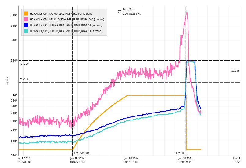
david.barker@LIGO.ORG - posted 10:12, Saturday 15 June 2024 (78455)
Sat CP1 Fill
Sat Jun 15 10:10:28 2024 INFO: Fill completed in 10min 25secs
Images attached to this report
Sat Jun 15 10:10:28 2024 INFO: Fill completed in 10min 25secs
TITLE: 06/15 Day Shift: 1430-2330 UTC (0730-1630 PST), all times posted in UTC
STATE of H1: Lock Acquisition
OUTGOING OPERATOR: Corey
CURRENT ENVIRONMENT:
SEI_ENV state: CALM
Wind: 19mph Gusts, 15mph 5min avg
Primary useism: 0.05 μm/s
Secondary useism: 0.08 μm/s
QUICK SUMMARY:
IFO is LOCKING at MOVE_SPOTS
IFO was mid auto relock from its last lockloss at 12:56 UTC when I arrived. Expect to get locked and observing soon.
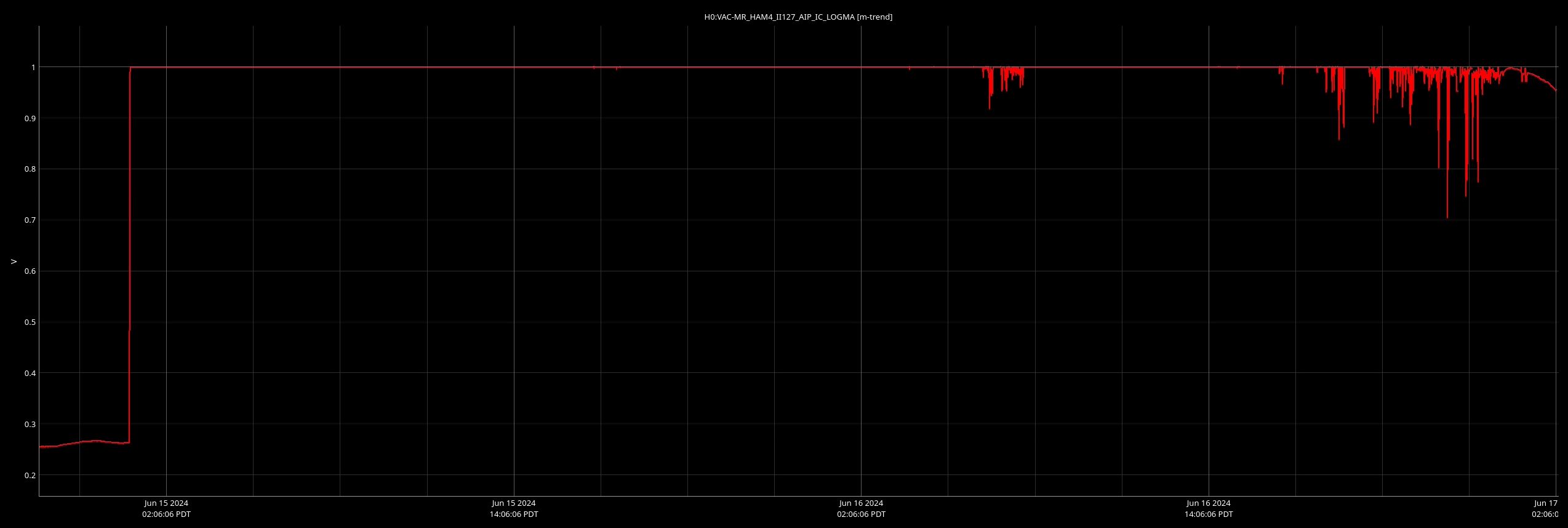
HAM4 annulus ion pump signal railed about 7:50 utc 06/15/2024. No immediate attention is required, per trend of PT120, an adjecent gauge, the internal pressure does not appear to be affected. HAM4 AIP will be assesed next Tuesday.
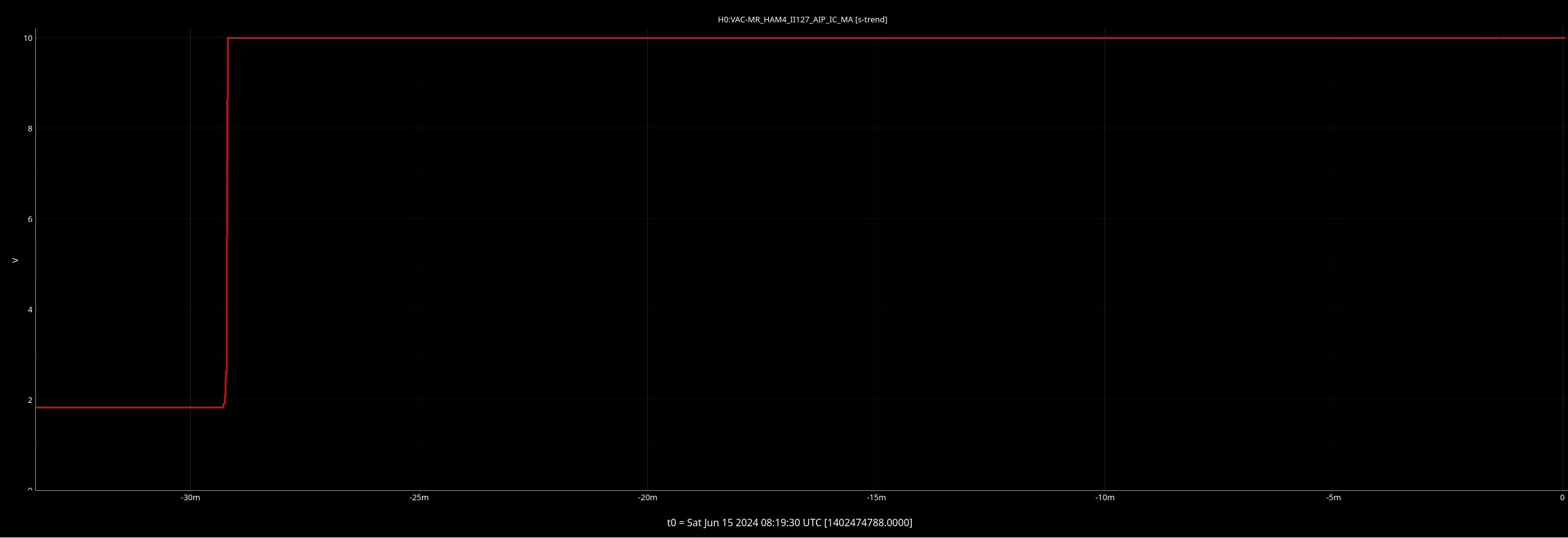
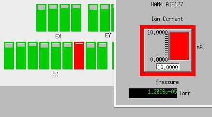
AIP is showing some good signs of coming back, see plot attached, regardless, we will keep the appointment to go and investigate this system on Tuesday.
TITLE: 06/15 Eve Shift: 2300-0800 UTC (1600-0100 PST), all times posted in UTC
STATE of H1: Observing at 148Mpc
INCOMING OPERATOR: Corey
SHIFT SUMMARY: We are Observing at 150 Mpc and have been locked for 13 hours now. Super quiet shift with no issues.
LOG:
23:00 Detector Observing and Locked for over 4 hours
| Start Time | System | Name | Location | Lazer_Haz | Task | Time End |
|---|---|---|---|---|---|---|
| 23:31 | PCAL | Francisco | PCAL Lab | y(local) | Putting covers on | 23:33 |
We are Observing at 154 Mpc and have been Locked for over 9 hours. Nothing to note
We continue the activities with the experimental vacuum chamber in the Mechanical Room, along the Eastern-wall. Now we are running another scroll pump there. Similarly to the already running one, a foam is placed underneath it.
In the meantime, the bakeout of this chamber's RGA has been finished.
TITLE: 06/14 Day Shift: 1430-2330 UTC (0730-1630 PST), all times posted in UTC
STATE of H1: Observing at 147Mpc
INCOMING OPERATOR: Oli
SHIFT SUMMARY:
IFO is in NLN and OBSERVING as of 21:33 UTC.
21:07 UTC to 21:33 UTC: COMISSIONING
19:28 UTC to 21:07 UTC: OBSERVING
Things of note:
LOG:
| Start Time | System | Name | Location | Lazer_Haz | Task | Time End |
|---|---|---|---|---|---|---|
| 15:29 | PCAL | Tony | Pcal Lab | Local | LLO Measurements | 17:59 |
| 16:33 | PCAL | Francisco | Pcal Lab | Local | LLO Measurements | 17:21 |
| 17:13 | SQZ | Sheila | LVEA | Y | Move magnetometer | 17:59 |
| 19:03 | PCAL | Tony, Miriam | PCAL Lab | N | LLO Measurements | 19:55 |
| 19:43 | RUN | Camilla, Neil | Y Arm | N | Improve and/or maintain health | 19:43 |
| 19:56 | PCAL | Francisco | PCAL | N | Preparing for lab upgrade steps | 19:58 |
| 22:12 | PCAL | Francisco, Miriam | PCAL Lab | Local | Preparing for lab upgrade steps | 22:40 |
| 22:41 | SAF | LVEA | LVEA | YES | LVEA IS LASER HAZARD | 15:52 |
| 22:42 | WALK | Francisco, Miriam | Overpass | N | Walking | 23:02 |
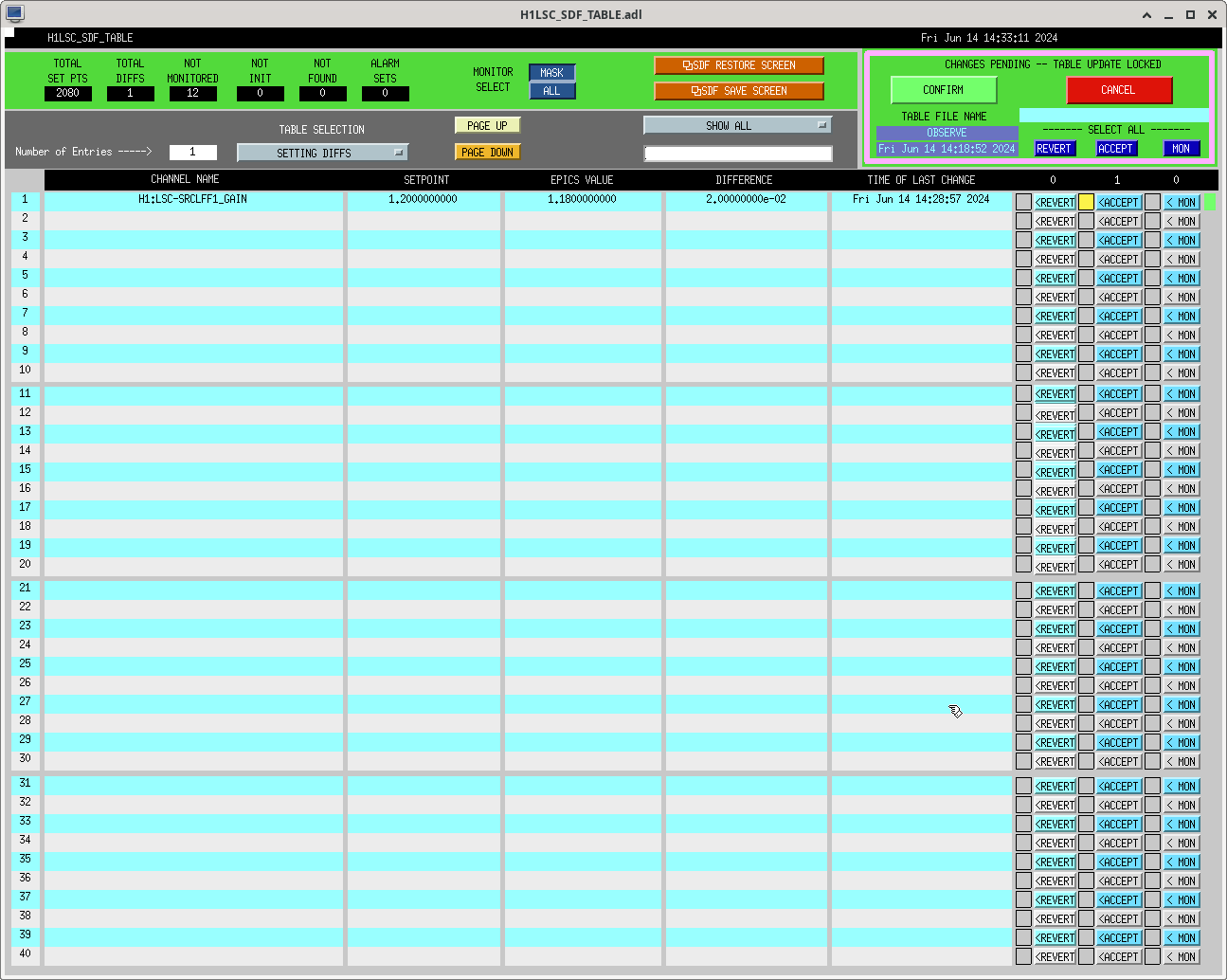
SRCLFF gain started as 1.14, was adjusted to 1.2 then readjusted to 1.18. First sdf accepted attached.

TITLE: 06/14 Eve Shift: 2300-0800 UTC (1600-0100 PST), all times posted in UTC
STATE of H1: Observing at 147Mpc
OUTGOING OPERATOR: Ibrahim
CURRENT ENVIRONMENT:
SEI_ENV state: CALM
Wind: 5mph Gusts, 3mph 5min avg
Primary useism: 0.02 μm/s
Secondary useism: 0.10 μm/s
QUICK SUMMARY:
Detector Observing and has been locked for over 4 hours. Range isn't great, around 148 MPc, but besides that everything is good.
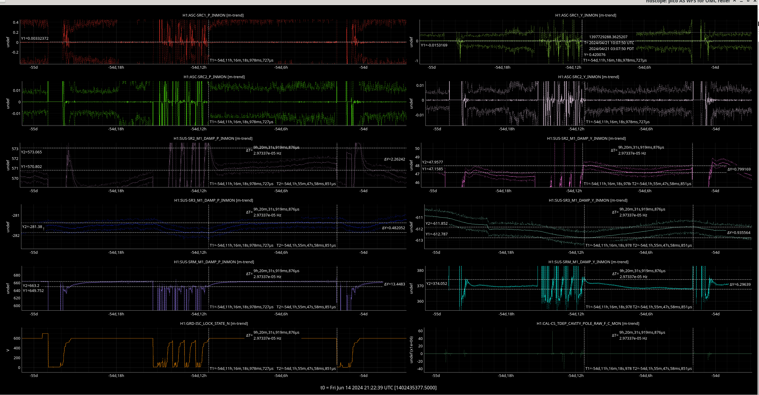
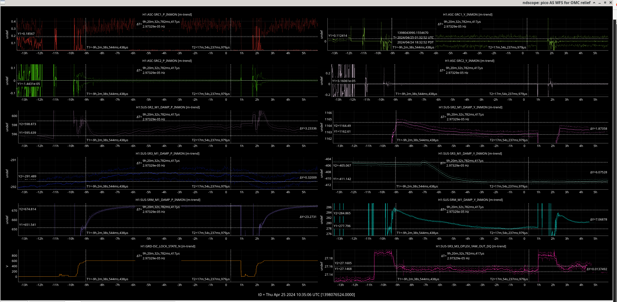
I looked at the SUS-{SR2,SR3,SRM_M1_DAMP_{P,Y}_INMON channels for a period on the 21st April before the OFI, and after we had re-aligned through the OFI to rcover our optical gain on the 25th April after the OFI burn.
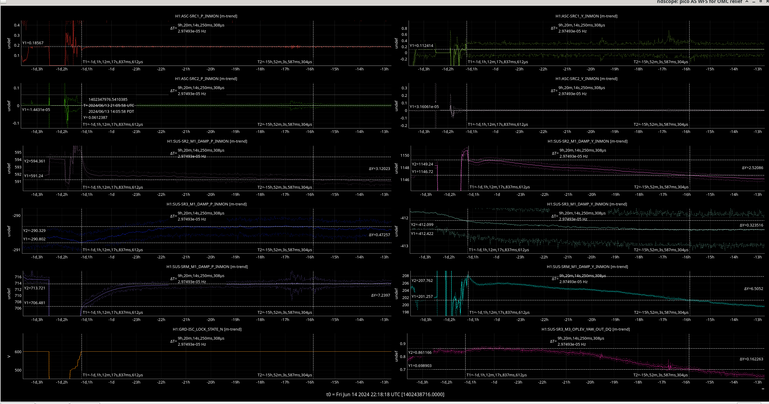
I have compared these to the drift in alignment in the signal extraction cavity yesterday. This is partly to figure out why we have to keep retuning our SRCL feedfoward.
| Date | Mirror | delta pitch value | delta yaw value |
| 21st April | SR2 | 2 | 0.8 |
| 25th April | SR2 | 3 | 2 |
| 13th June | SR2 | 3 | 3 |
| 21st April | SR3 | 0.5 | 0.9 |
| 25th April | SR3 | 0.3 | 6 |
| 13th June | SR3 | 0.5 | 0.3 |
| 21st April | SRM | 13 | 6 |
| 25th April | SRM | 23 | 7 |
| 13th June | SRM | 7 | 7 |
The only angular degrees of freedom that changed significantly between these dates were:
Ibrahim, Sheila, Camilla
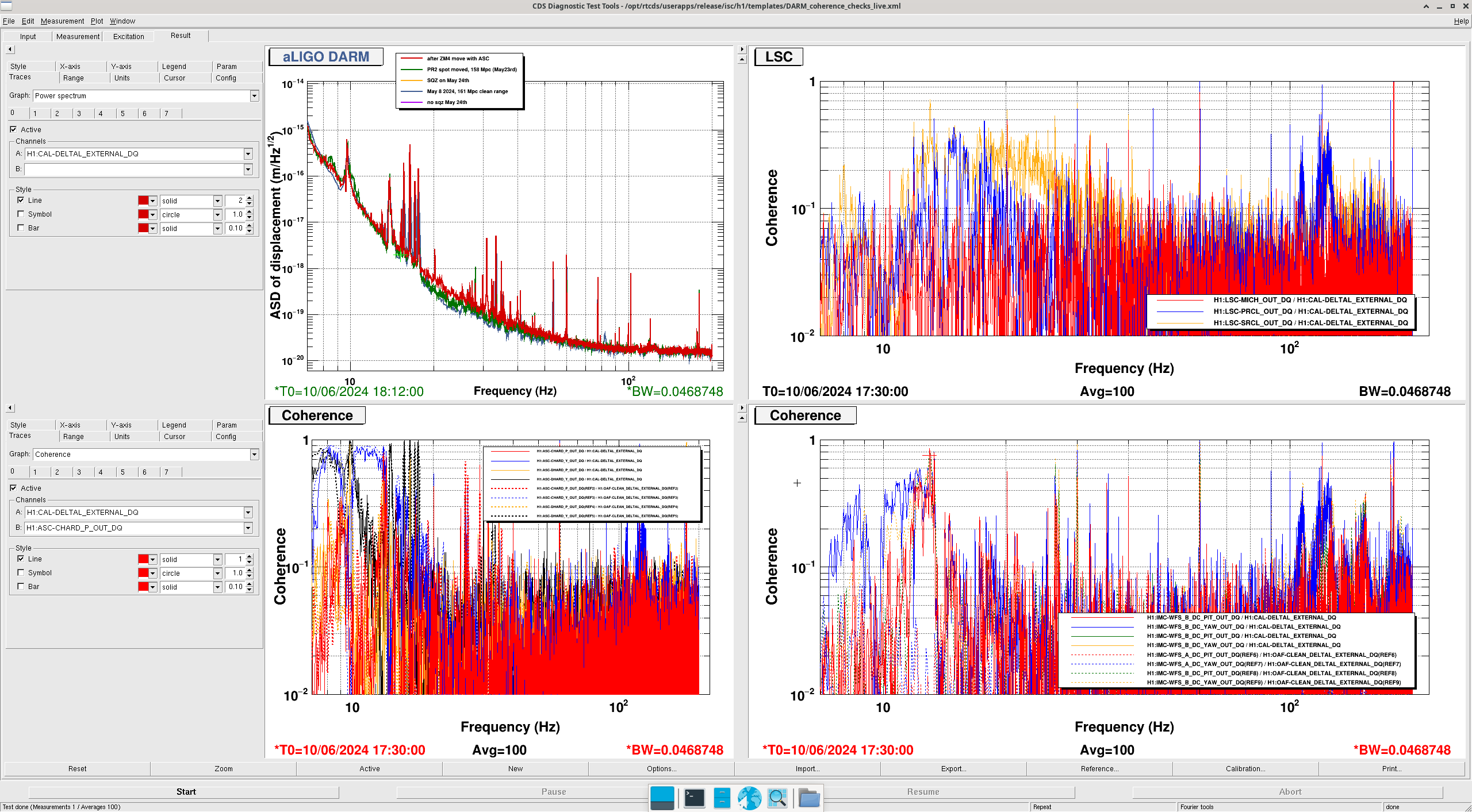
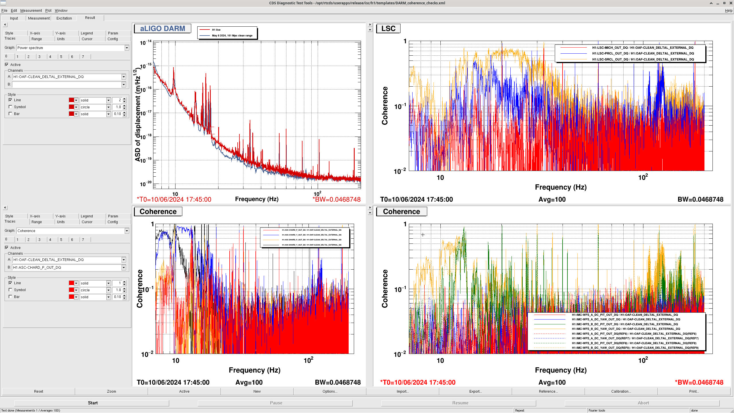
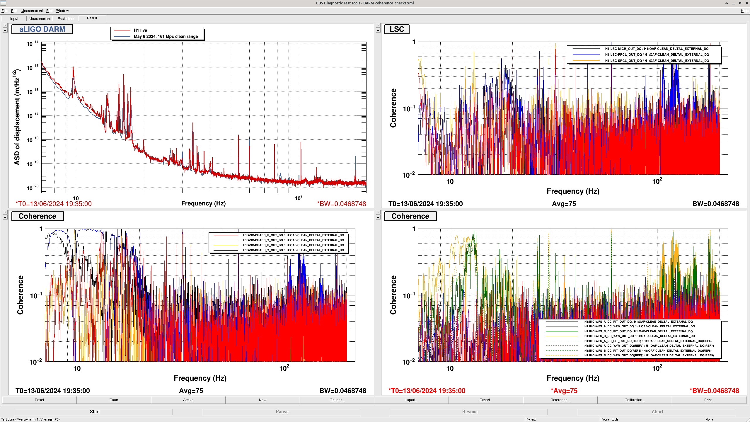
After Ibrahim relocked the IFO, the range is lower around 150 Mpc. Ibrahim ran the coherence checks from the low range wiki, and saw that there was braod SRCL coherence. He double checked that the SRC ASC offsets 78415 from yesterday are correctly still in place. The squeezing level is quite good in this lock.
I accidentally started to run the A2L script (by clicking in a terminal I didn't mean to), so we took a few minutes to try to retune SRCL FF. We tried the feedforward that Gabriele fit last week, 78307, which gives us worse coupling than the April 29th filters do. Then we adjusted the gain using the April 29th filter, screenshot attached. The SRCL coherence is still highly, and the range is still low. We would need a new filter to get good SRCL decoupling in this lock, but we do not understand why this has changed since last lock.
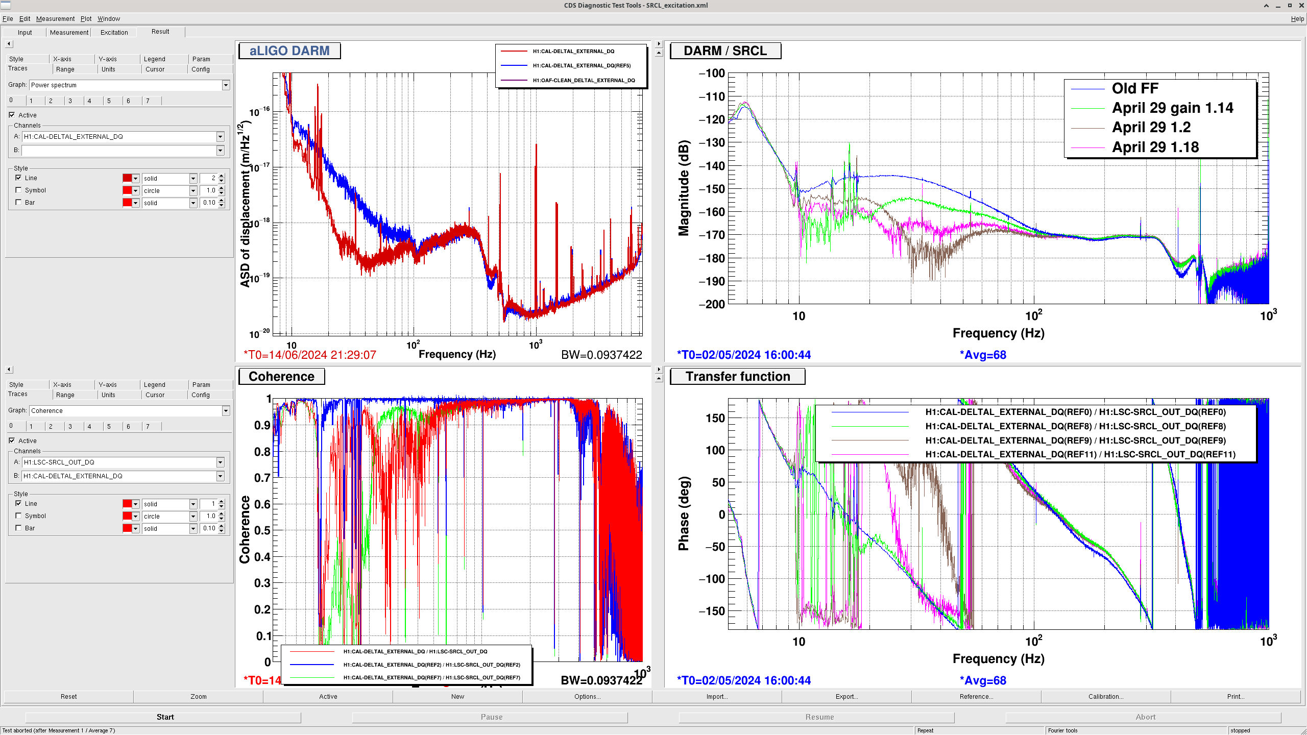
DARM Coherence Plots below (labeled as before and after changes)
IFO is in NLN and OBSERVING as of 19:26 UTC
Mini-Events Today:


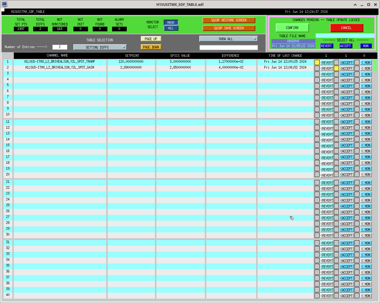


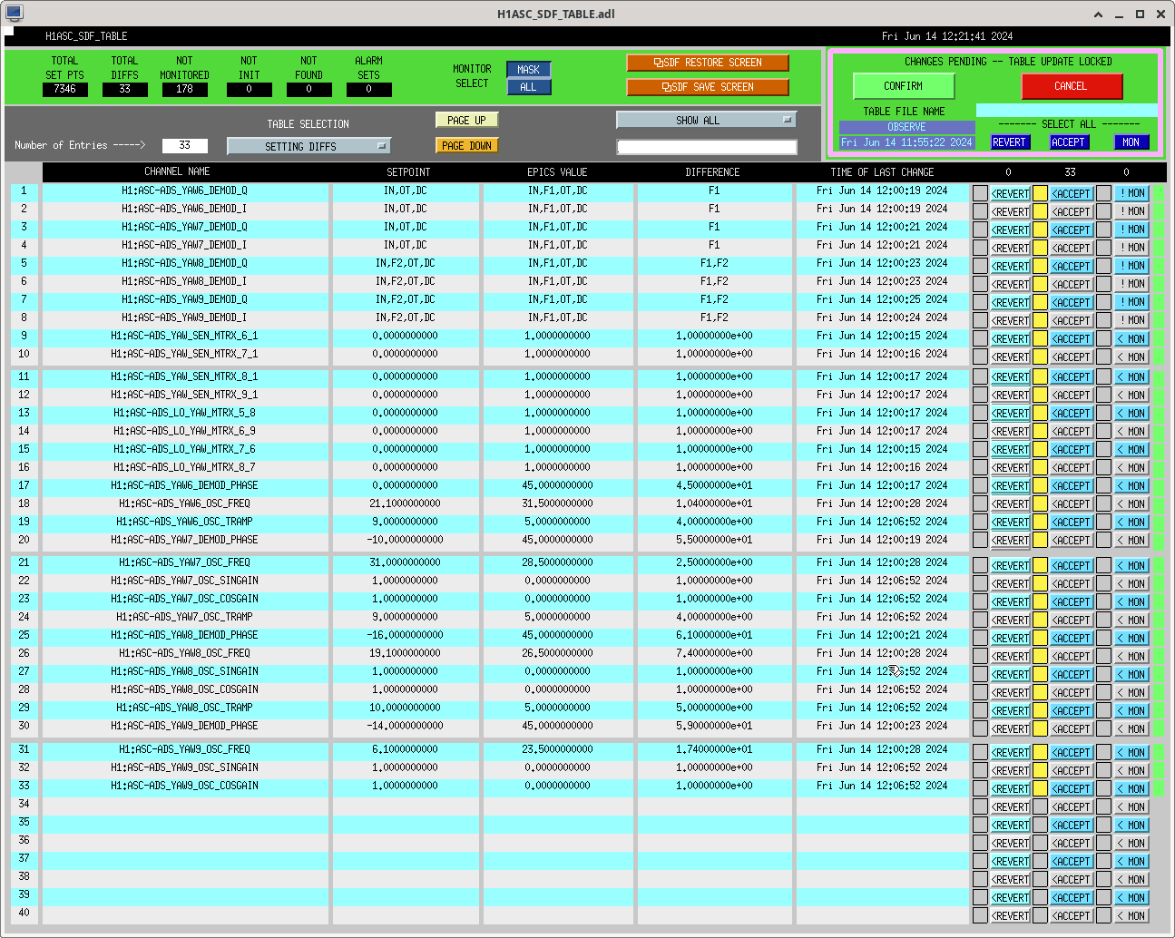
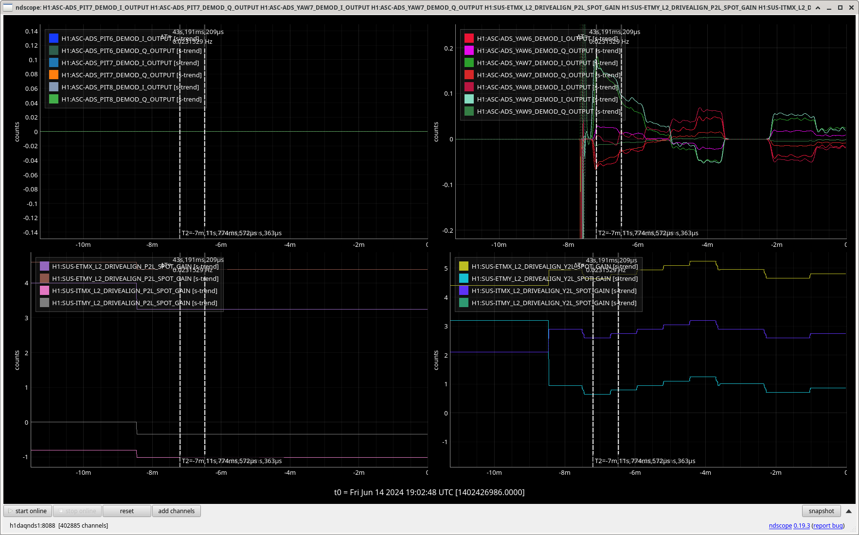
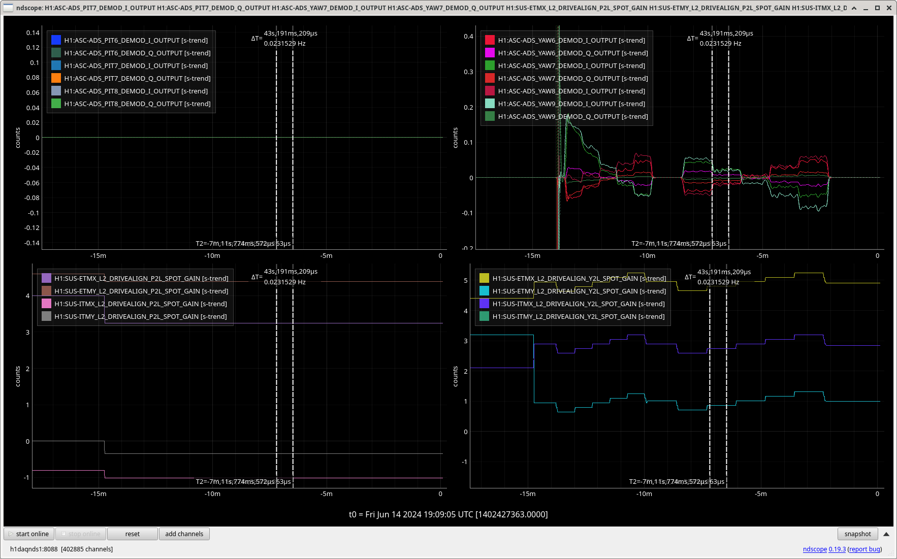
Since the yaw ASC cross couplings to DARM were high in our last lock, Ibrahim and I took a couple minutes before going into observing to run the script that TJ edited yesterday (78419) again. The attached screenshot shows that in our first time running the script the ADS values were still drifting when the script moved on to measuring the next step. This might have been because the IFO had locked recently, or because it needs to wait longer. We added a 30 second wait after we change the A2L gains before checking the values by adding +30 on line 185, after this it looked like things had settled well.
We ran the script for all test masses yaw only from the terminal using: python a2l_min_multi.py --quads ETMX ETMY ITMX ITMY --dofs Y
After the script ran, there were many SDF diff that Ibrahim has screenshots of. It would be good to edit the end of the script to have fewer of these diffs each time we run it. We added these new values to lscparams and loaded ISC_LOCK.
Here are our first and second run results.
*************************************************
RESULTS
*************************************************
ETMX Y
Initial: 4.94
Final: 4.95
ETMY Y
Initial: 0.94
Final: 1.01
ITMX Y
Initial: 2.89
Final: 2.89
ITMY Y
Initial: -2.51
Final: -2.39
Diff: 0.11999999999999966
*************************************************
RESULTS
*************************************************
ETMX Y
Initial: 4.95
Final: 4.91
Diff: -0.040000000000000036
ETMY Y
Initial: 1.01
Final: 1.0
Diff: -0.010000000000000009
ITMX Y
Initial: 2.89
Final: 2.85
Diff: -0.040000000000000036
ITMY Y
Initial: -2.39
Final: -2.45
Diff: -0.06000000000000005
Woke up to see that the SQZ_OPO_LR Guardian had the message:
"disabled pump iss after 10 locklosses. Reset SQZ-OPO_ISS_LIMITCOUNT to clear message"
Followed 73053, but did NOT need to touch up the OPO temp (it was already at its max value); then took SQZ Manager back to FRE_DEP_SQZ, and H1 went back to OBSERVING.
Received wake-up call at 440amPDT (1140utc). Took a few minutes to wake up, then log into NoMachine. Spent some time figuring out the issue, and ultimately doing an alog search to find steps to restore SQZ (found an alog by Oli which pointed to 73053). Once SQZ relocked, automatically taken back to OBSERVING at 517am(1217utc).
Sheila, Naoki, Camilla. We've adjusted this so it should automacally relock the ISS.
IFO went out of observing from the OPO without the OPO Guardian going down as the OPO stayed locked, just turned it's ISS off. We're not sure what the issue with the ISS was, SHG power was fine as the controlmon was 3.5 which is near the middle of the range. Plot attached. It didn't reset until Corey intervened.
* this isn't really a lockloss counter, more of a count of how many seconds the ISS is saturating.
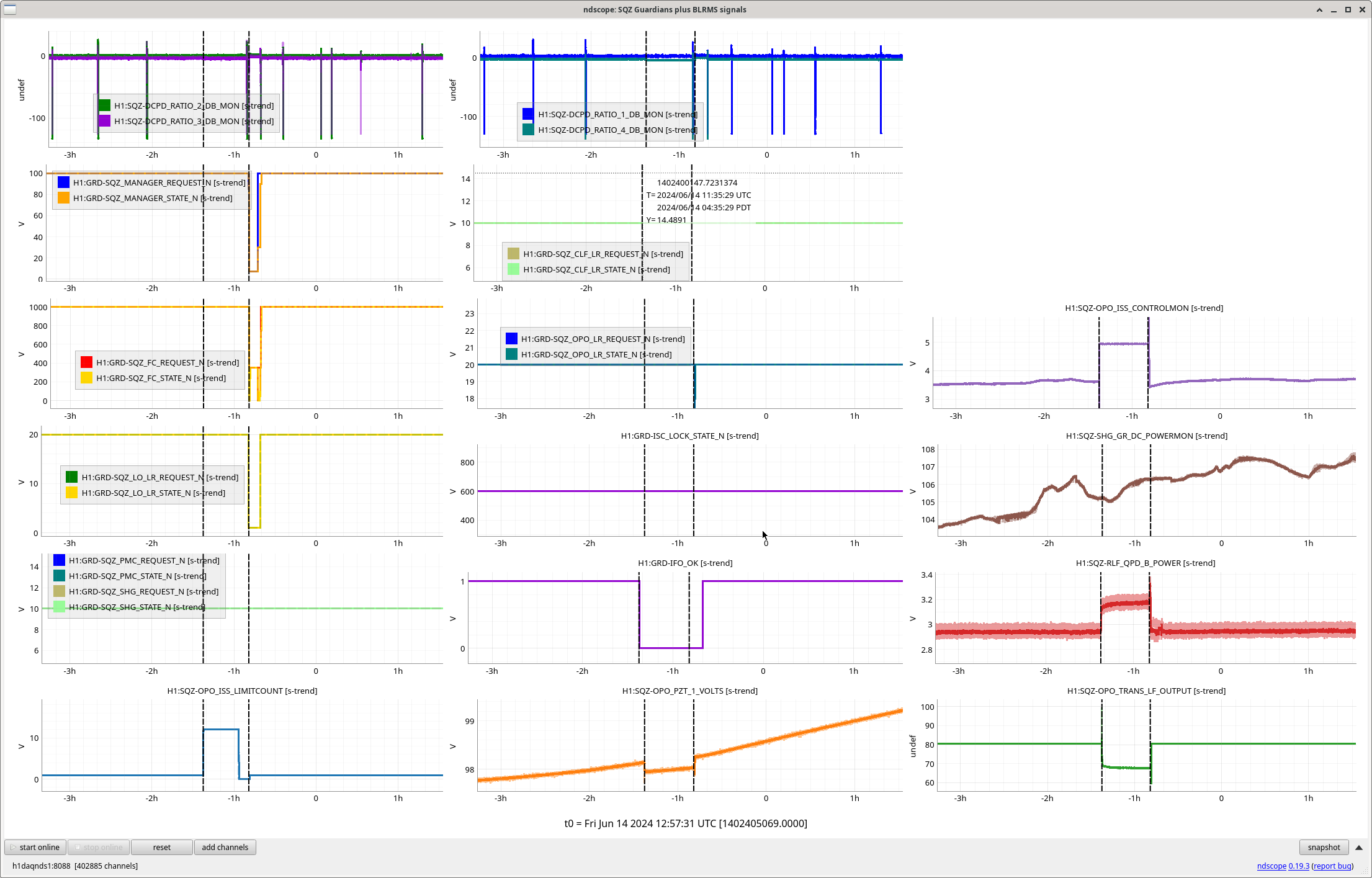
Worryingly the squeezing got BETTER while the ISS was unlocked, plot attached of DARM, SQZ BLRMs and range BLMS.
In the current lock, the SQZ BLRMs are back to the good values plot, why was the ISS injecting noise last night? Has this been a common occurrence? What is a good way of monitoring this? Coherence with DARM and the ISS
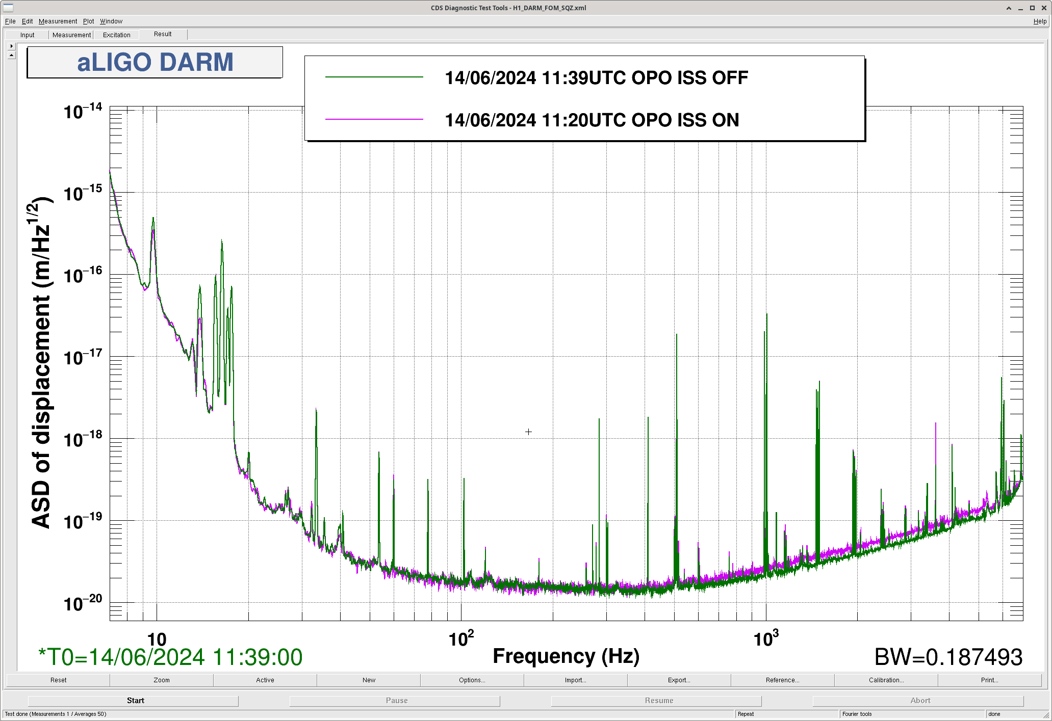
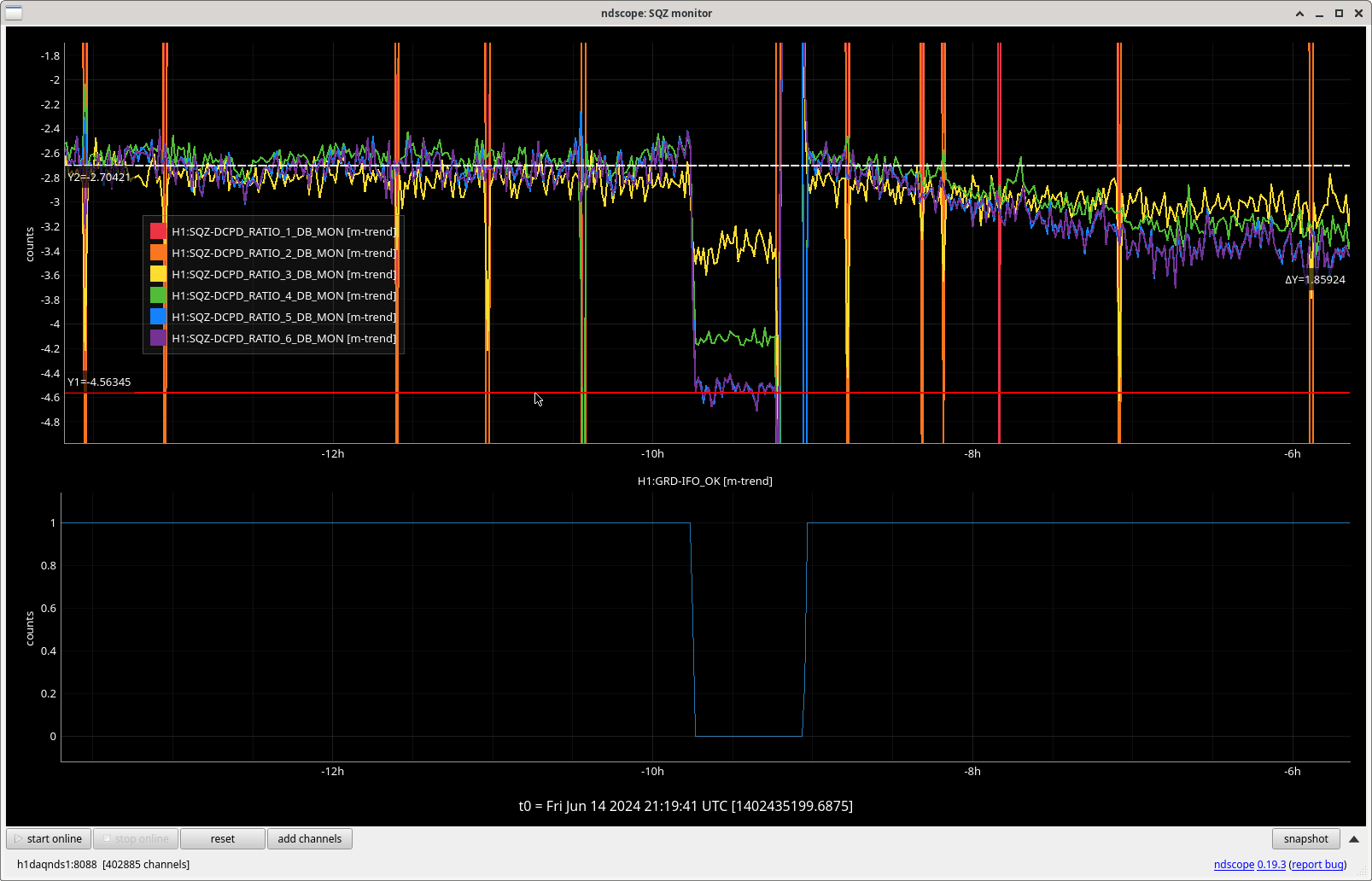

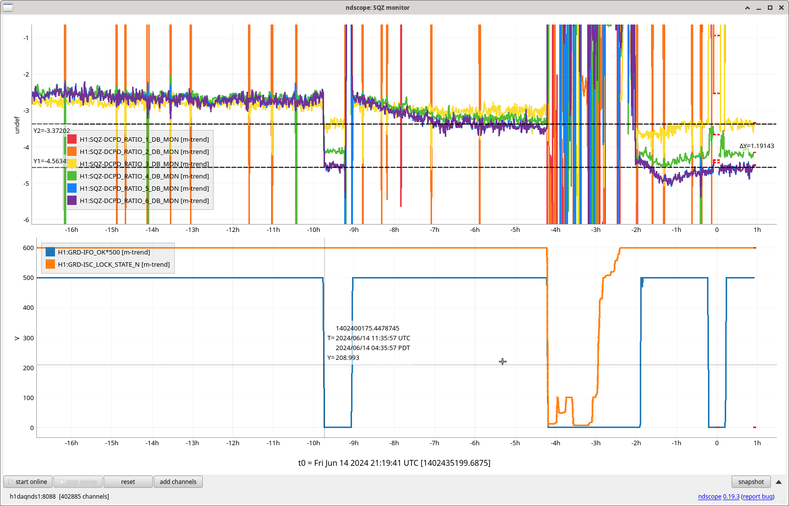
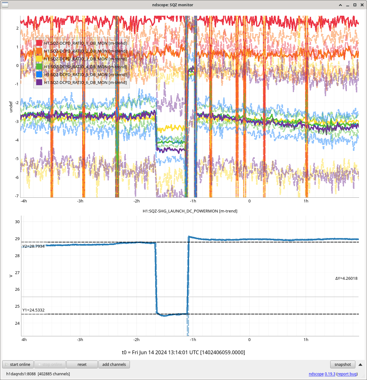
Check on this is 78486. Think that the SQZ OPO temperature or angle wasn't well tuned for the green OPO power at this time, when the OPO ISS was off, the SHG launch power dropped from 28.8mW to 24.5mW, plot. it was just chance that SQZ was happier here.
State of H1: Observing at 157Mpc, locked for 6.5 hours.
Quiet shift so far except for another errant Picket Fence trigger to EQ mode just like ones seen last night (alog78404) at 02:42 UTC (tagging SEI).
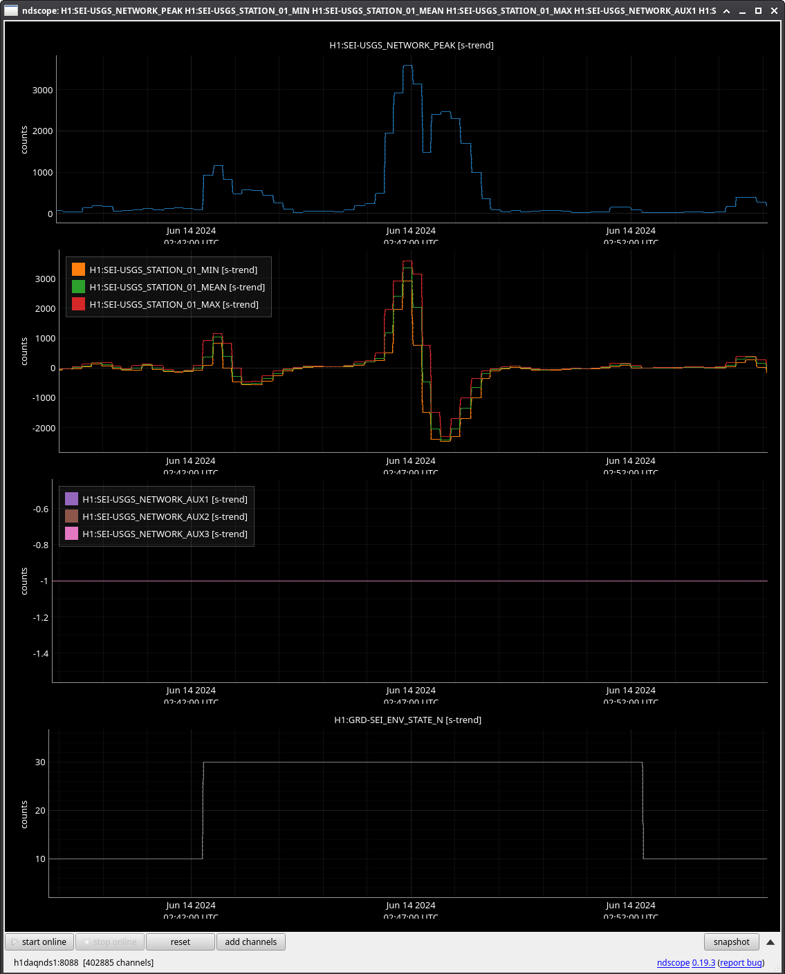
That's about two triggers in a short time. If the false triggers are an issue, we should consider triggering on picket fence only if there's a Seismon alert.
The picket fence-only transition was commented out last weekend on the 15th by Oli. We now will only transition on picket fence signals if there is a live seismon notificaition.
Thanks Jim,
I'm back from my vacation and will resume work on the picket fence to see if we can fix these errant triggers this summer.
I took the script that we have been using to run our A2L and converted it to run the measurements for all quads and degrees of freedom at the same time, or less, as desired. The new script is (userapps)/isc/h1/scripts/a2l/a2l_min_multi.py. Today Sheila and I tested it for all quads with just Y with the results below. These values were accepted in SDF, updated in lscparams.py, and ISC_LOCK reloaded. More details about the script at the bottom of this log.
Results for ETMX Y
Initial: 4.99
Final: 4.94
Diff: -0.04999999999999982
Results for ETMY Y
Initial: 0.86
Final: 0.94
Diff: 0.07999999999999996
Results for ITMX Y
Initial: 2.93
Final: 2.89
Diff: -0.040000000000000036
Results for ITMY Y
Initial: -2.59
Final: -2.51
Diff: 0.08000000000000007
The script we used to use was (userapps)/isc/common/scripts/decoup/a2l_min_generic_LHO.py which was, I think, originally written by Vlad B. and then Jenne changed it up to work for us at LHO. I took this and changed a few things around to then call the optimiseDOF function for each desired quad and dof under a ThreadPool class from multiprocess to run all of the measurements simultaneously. We had to move or change filters in the H1:ASC-ADS_{PIT,YAW}{bank#}_DEMOD_{SIG, I, Q} banks so that each optic and dof is associated with a particular frequency and used the ADS banks 6-9. These frequencies needed to be spaced apart enought but still within our area of interest. We also had to engage notches for all of these potential lines in the H1:SUS-{QUAD}_L3_ISCINF_{P,Y} banks (FM6&7). We also accepted the ADS output matrix values in SDF for these new banks with a gain of 1.
This hasn't been tested for all quads and both P&Y, so far only Y.
Here's a screenshot of the ASC coherence after TJ ran this script yesterday, there is still high coherence with YAW ASC and DARM.
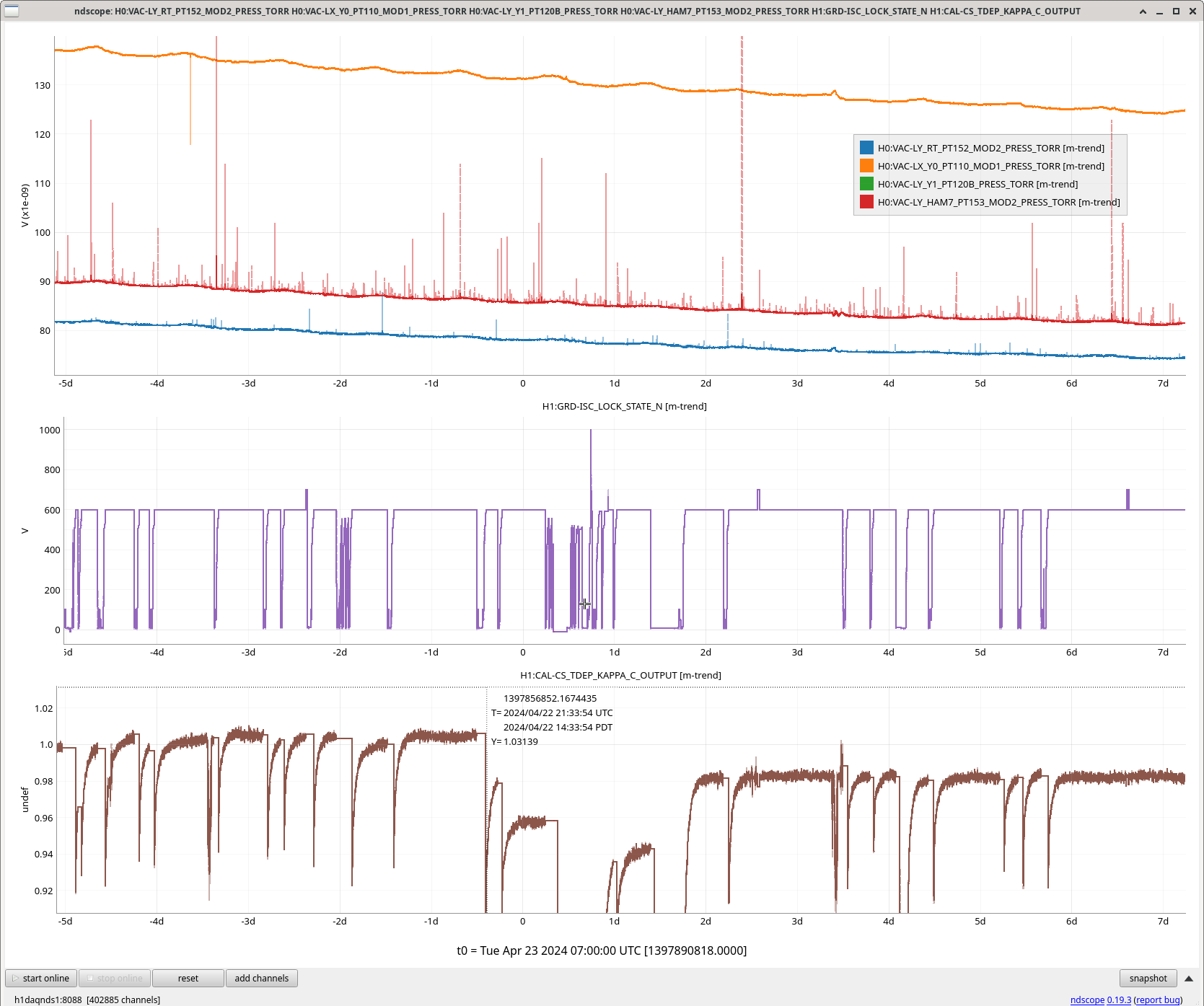
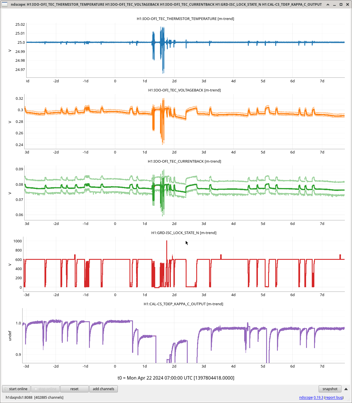
Following on from Sheila's alog 77427, checked on VAC trends and OFI temperature around April 22nd.
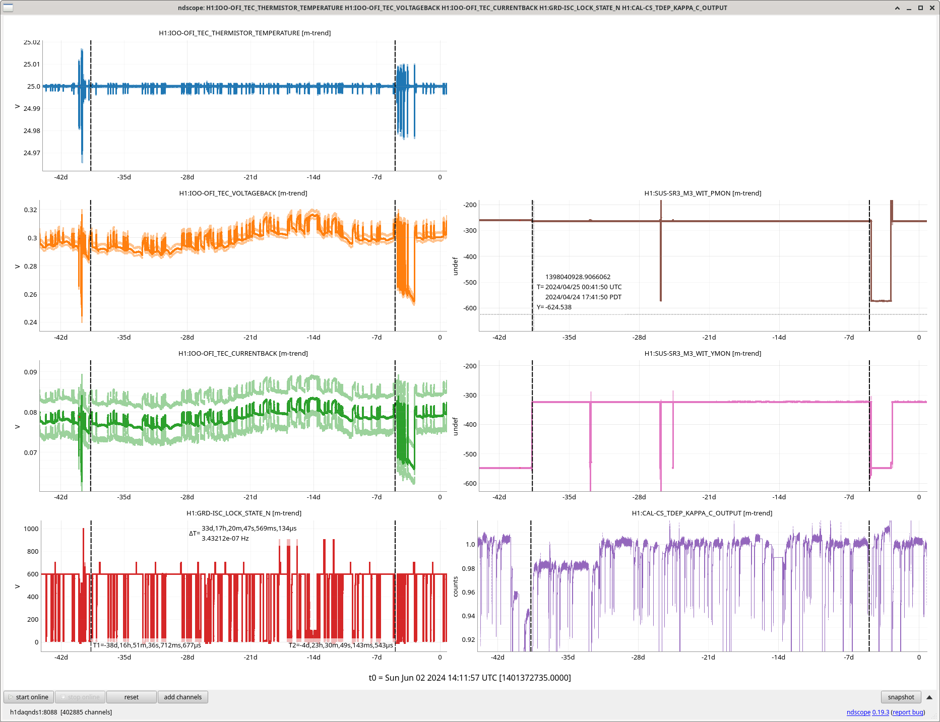
I checked (maybe a repeat of someone else) that there were no vacuum spikes during the locks when Kappa_C dropped or the locklosses afterwards. Plot of Kappa_ C with VAC channels attached.
Looking at the OFI TEC readbacks during that time, they were significantly noisier than usual during Tuesday maintenance after the 5% optical gain drop, before out alignment shift. Noisy between 6:30am and 4pm. This is before any Tuesday maintenance 77363 or injections start. Plot attached, including zoom out and zoom in. It also happened the May 28th to May 30th.
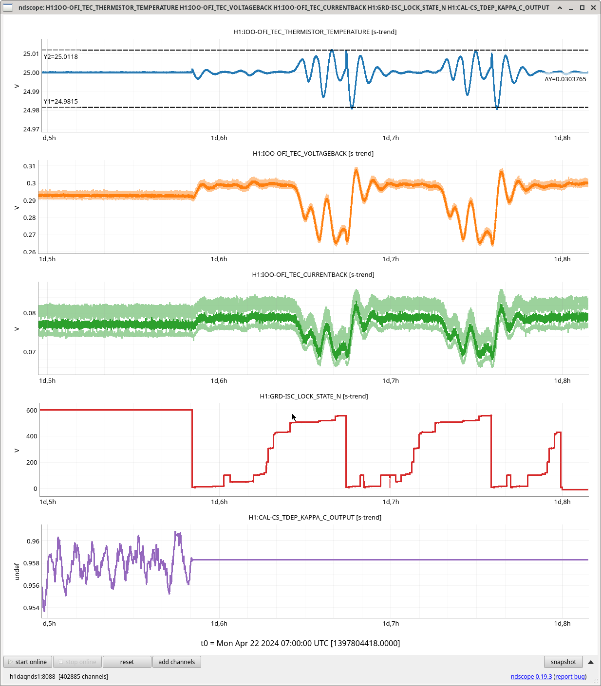
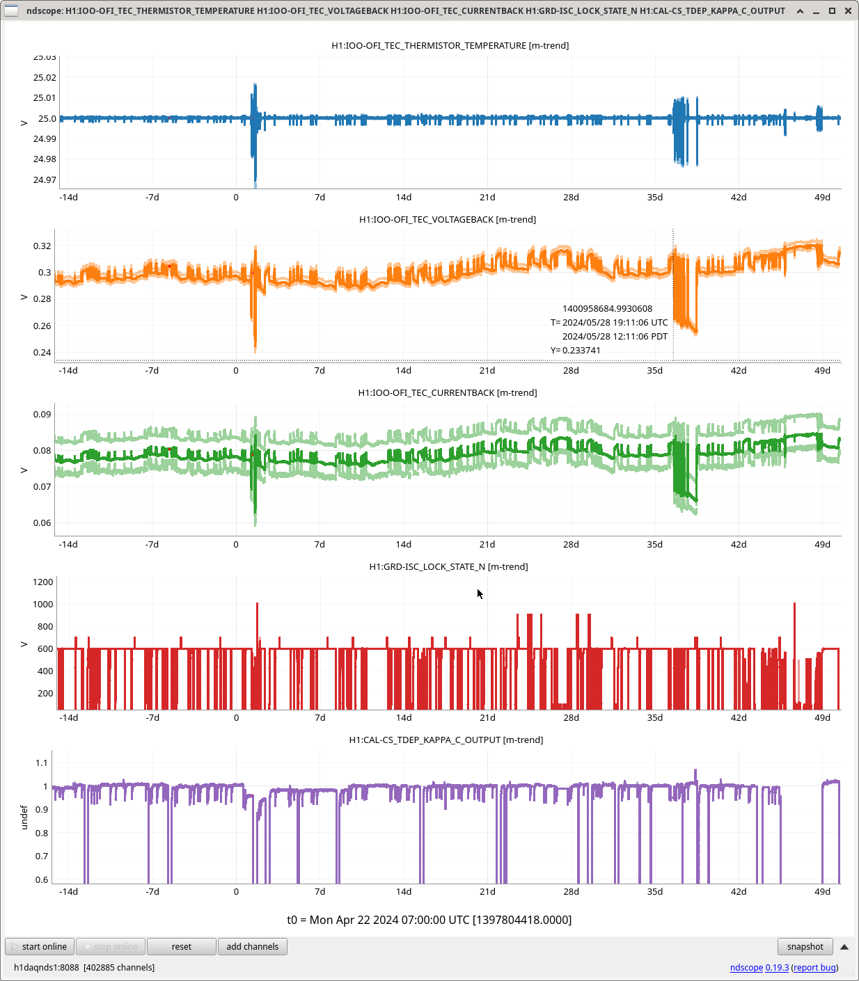
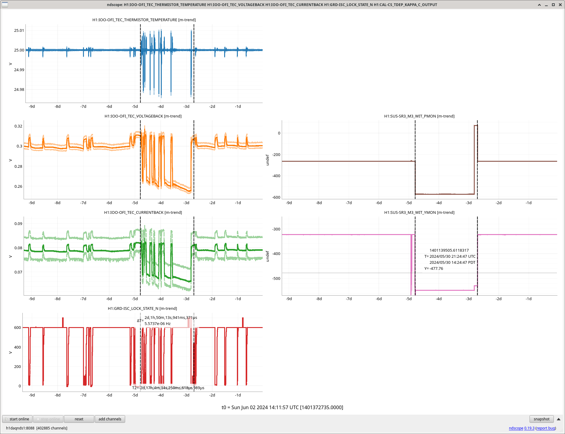
In 78442, we show that these larger than usual OFI temperature swings on locklosses and powerups so happened May 28th/29th when we adjusted our SRC alignment (SRC 250urad). Is this a sign there is an alignment where we are hitting something in the OFI?
Last night and today we are in a different spot through the OFI. See Sheila's alog 78096 for the move that was made.
Overall, SR2 and SRM yaw are much closer to center in this position, however SRM pitch is farther from center. I did a quick double check of the SRM pit, and indeed this is where it wants to be.
The previous spots (with the previous SR3 alignment) are recorded in alog 77443.
| ampl [cts] of line at 31.0 Hz | A2L gain step size when minimizing | CAL-DELTAL line reduction factor | Final A2L gain | Inferred new spot position [mm] | Change from alog 77443 position | |
| SR2 P2L | 1.0 | 0.1 | 100x | -1.0 | -2.0 | 13.1 mm other side of center |
| SR2 Y2L | 1.0 | 0.1 | 100x | +0.3 | 0.6 | 9.7 mm other side of center |
| SRM P2L | 2.0 | 0.1 | 50x | -5.5 | -11.1 | 4.3 mm farther from center |
| SRM Y2L | 2.0 | 0.1 | 30x | +1.85 | 3.7 | 3.5 mm closer to center |
Attached are the saved SDF diffs for both Observe and Safe snap files.
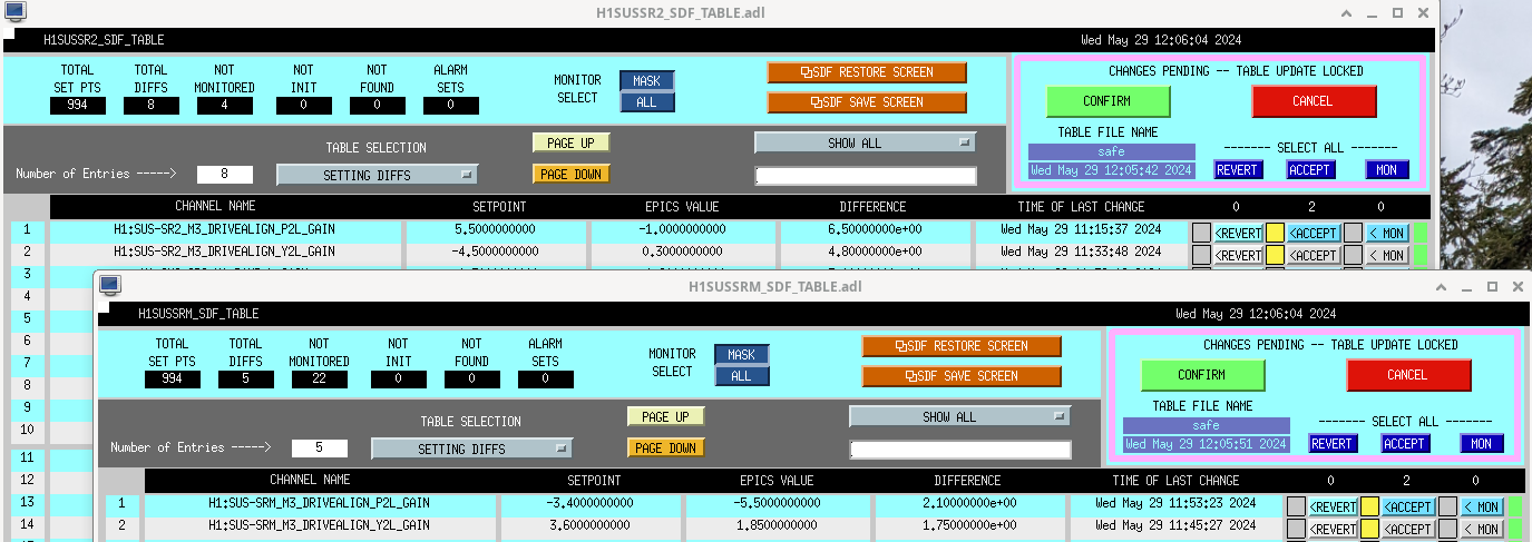
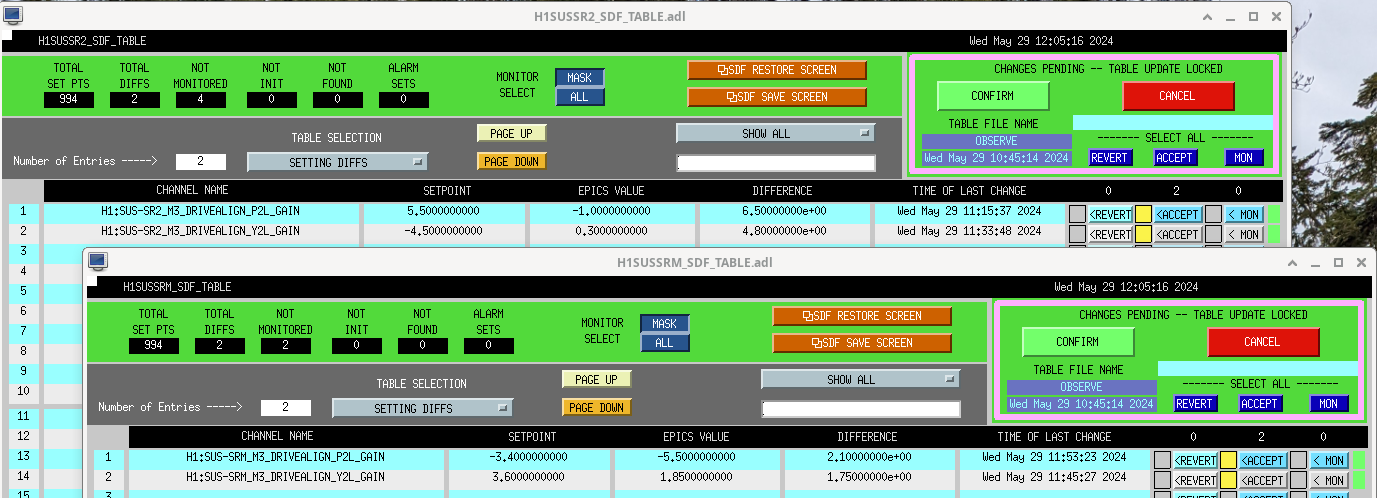
Sheila and Keita have recently found and fixed sign convention errors. Please see alog 78393 for the corrected interpretation of A2L gains.
Sheila, Camilla. During this May 28th/29th SRC alignment, the OFI sees larger than usual temperature swings on locklosses and powerups. See plot attached. We saw similar larger OFI temperature swings on the re-locking attempts after our April 22nd optical gain drop before we changes alignments, shown in 78399 and second attached plot. Is the beam in this alignment hitting something in the OFI? Could be more likely the yaw alignment as that is common in both alignments with larger temperature swings.
Today Dripta and I went to EY and did what would have previously call a standard ES measurement with PS4.
And We also employed the new End Station procedure.
Details and analysis ccoming in a comment to this alog.
A PCAL ENDY Station Measurement was done on May, the PCAL team (Dripta B. & Tony S.) went to ENDY with Working Standard Hanford aka WSH(PS4) and took two End station measurements to verify that the results were consistent with each other. One with our previous version of T1500062-V16 procedure and another with T1500062-V17.
The ENDY Station Measurements was carried out mostly according to the procedures outlined in Document LIGO-T1500062-v16 & v17, Pcal End Station Power Sensor Responsivity Ratio Measurements: Procedures and Log.
Measurement Log
First thing we did was take a picture of the beam spot before anything is touched!
Martel:
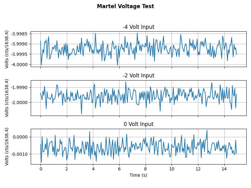
Martel Voltage source applies voltage into the PCAL Chassis's Input 1 channel. We record the GPStimes that a -4.000V, -2.000V and a 0.000V voltage was applied to the Channel. This can be seen in Martel_Voltage_Test.png . We also did a measurement of the Martel's voltages in the PCAL lab to calculate the ADC conversion factor, which is included on the above document.
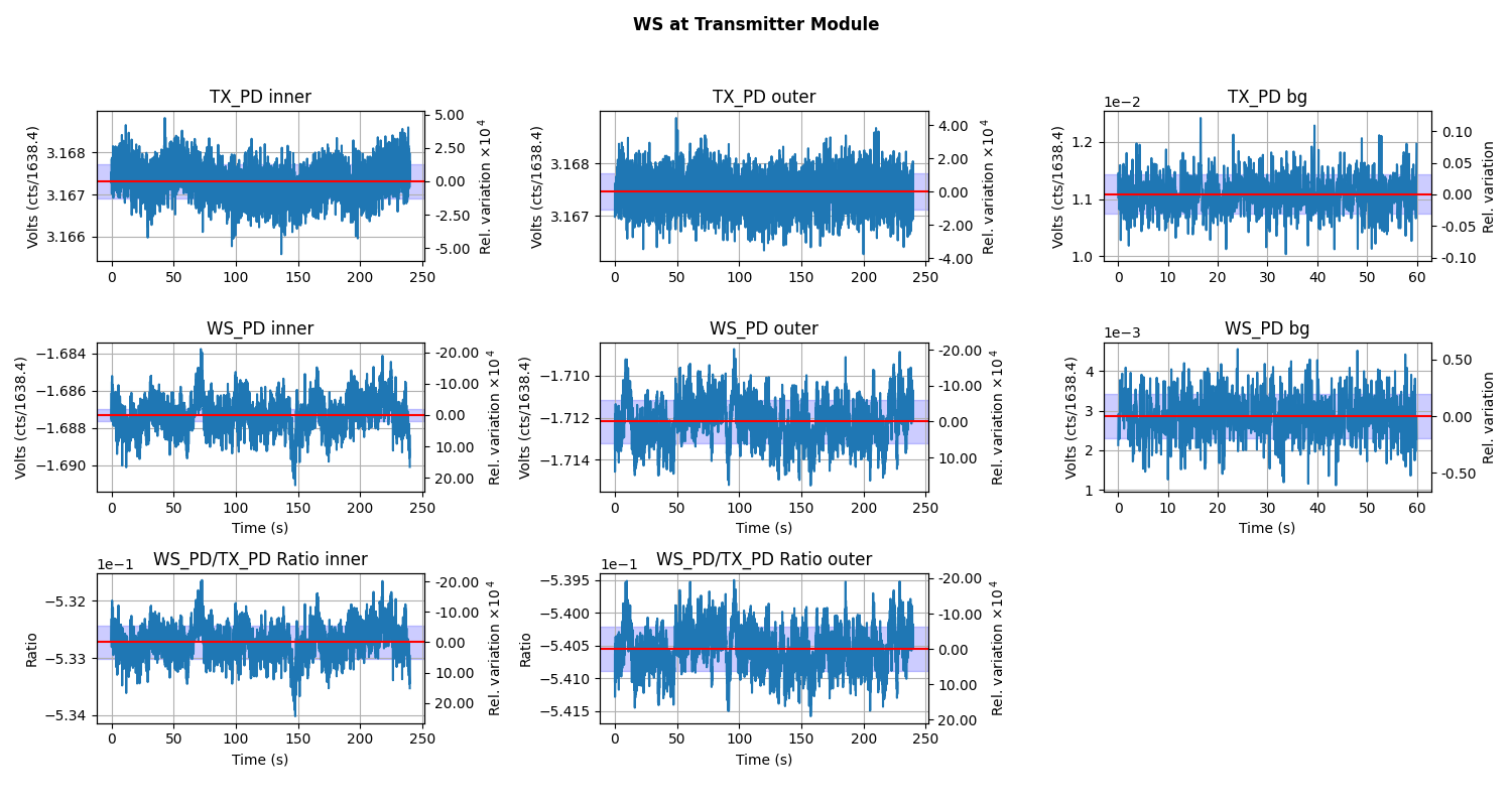
Plots while the Working Standard(PS4) is in the Transmitter Module during Inner beam being blocked, then the outer beam being block, followed by the background measurment: WS_at_TX.png.
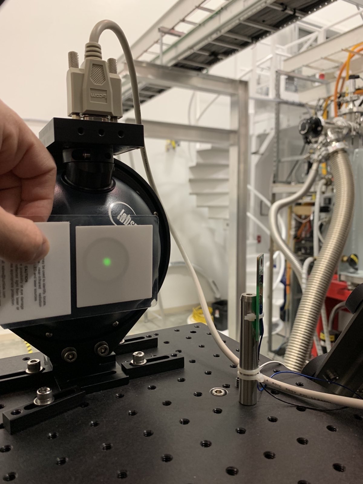
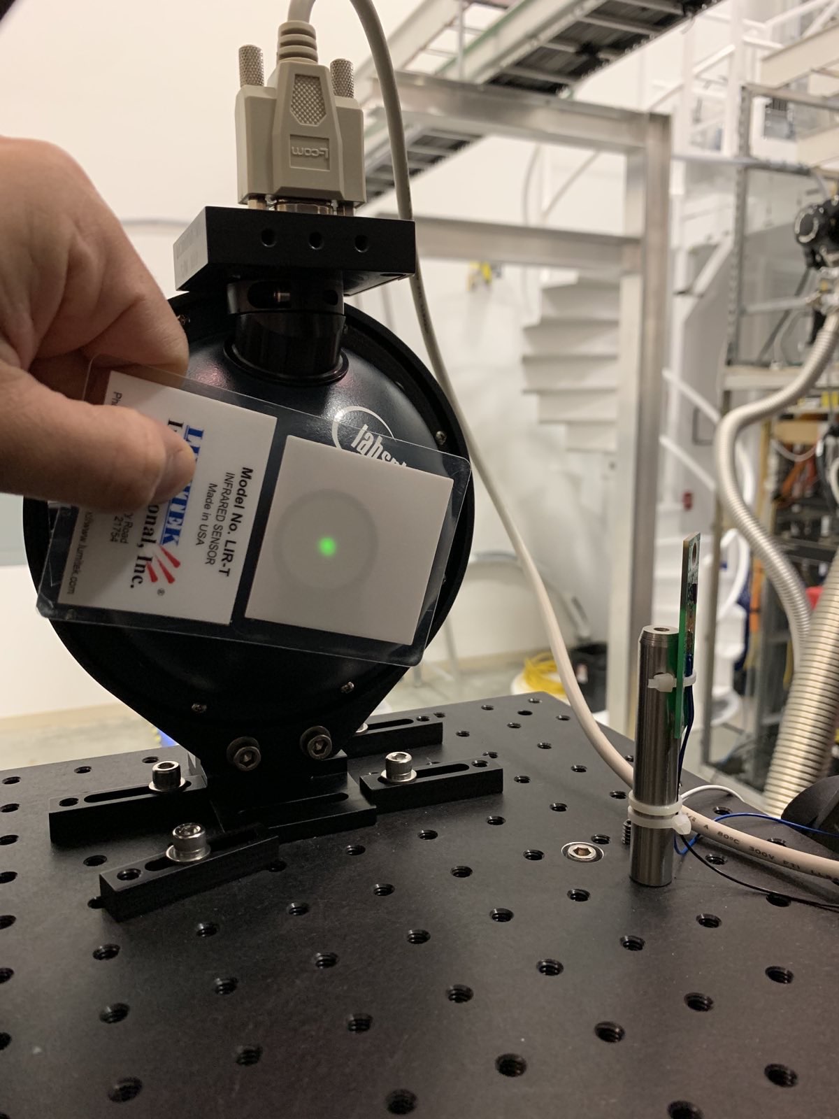
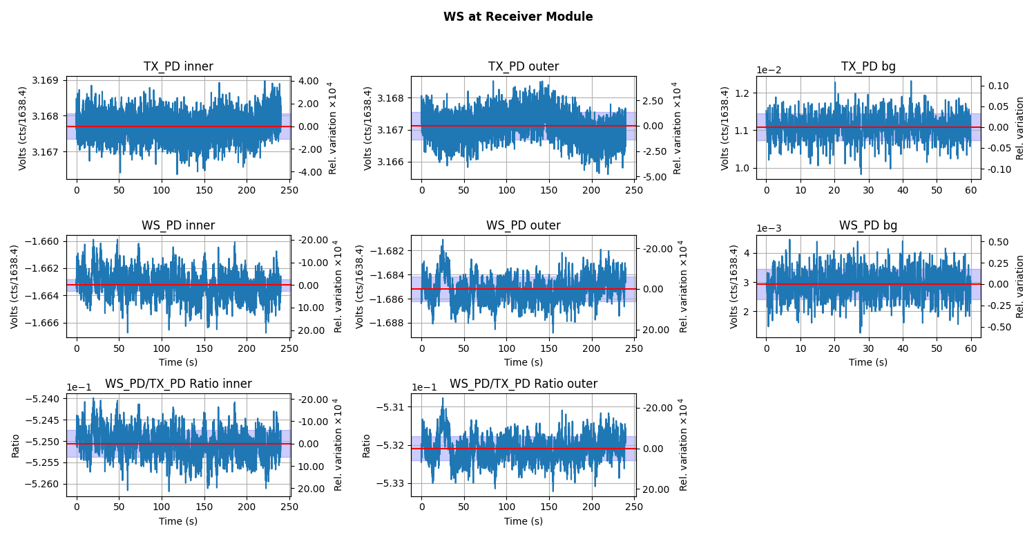
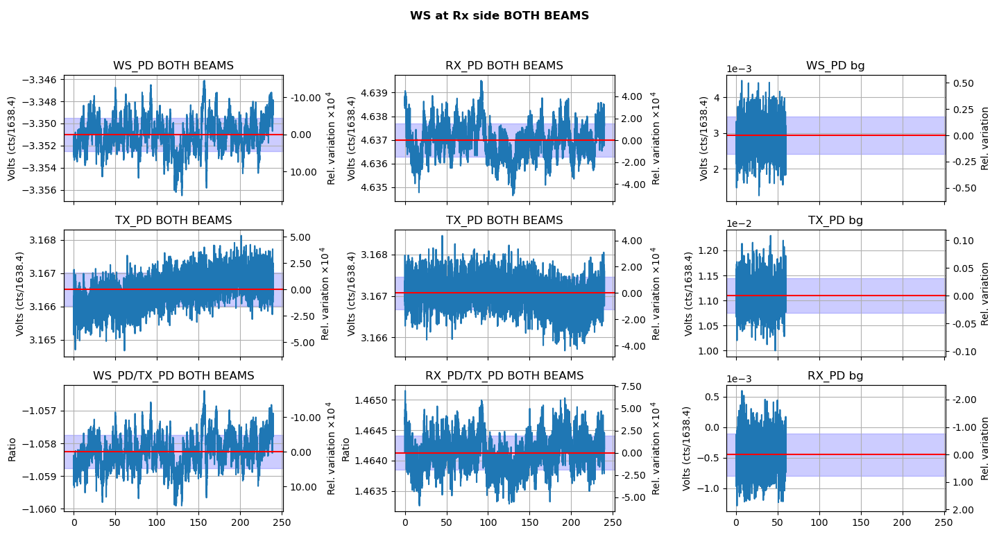
The Inner, outer, and background measurement while WS in the Receiver Module: WS_at_RX.png.
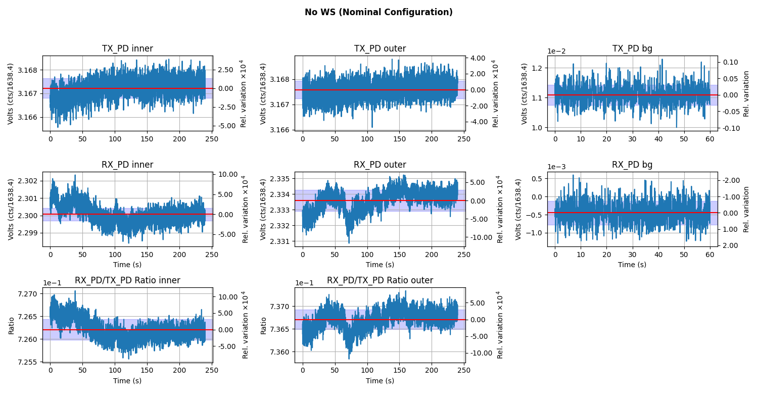
The Inner, outer, and background measurement while RX Sphere is in the RX enclosure, which is our nominal set up without the WS in the beam path at all.: TX_RX.png.
-----------------------------------------------------------------------------------------------------------------------------------------------
The New Document has a different order of measurements that are taken and are taken in a different way.
We placed the Working Standard (PS4) in the path of the INNER Beam at the TX module.
Then the Working Standard (PS4) in the path of the OUTER Beam at the TX module.
A background measurement.
Then we take the Working Standard and put it in the RX module to get the INNER Beam.
Then the OUTTER Beam in the RX Module.
And a Background.
This is where things get different....
We remove the beam block and give the Working Standard Both Inner and Outer Beams at the SAME TIME while it's at the RX module.
We also put the RX sphere back to the RX module and put both beams on it at the same time. Like nominal opperation when the PCAL lines are turned off.
Then we take a background.
This was repeated ~10 mins later because we wanted to see if there is any time dependent variations.
The last picture is of the Beam spots after we had finished the measurement.
Old procedure measurement results : "rhoR_prime": 10565.2
New Procedure Measurement: rhoR_prime : 10571.1. This 5 hop difference is well within our uncertainty .
second New Procedure rhoR_prime 10574.3, was off by less than 3hops ,well within uncertainty.
Preliminary analysis suggests that discrepancy in rhoRprime calculated via two methods is allowed within the uncertainty.
All of this data and Analysis has been commited to the SVN or GIT:
https://svn.ligo.caltech.edu/svn/aligocalibration/trunk/Projects/PhotonCalibrator/measurements/LHO_ENDY/
Obligitory BackFront PS4/PS5 Responsivity Ratio:
PCAL Lab Responsivity Ratio Measurement:
A WSH/GS (PS4/PS5)BF Responsivity Ratio measurement was ran, analyzed, and pushed to the SVN.
PS4PS5_alphatrends.pdf to show that the recent changes to the lab have not impacted the Lab measurements
This adventure has been brought to you by Dripta B. & Tony S.