thomas.shaffer@LIGO.ORG - posted 16:30, Tuesday 11 June 2024 (78379)
Ops Day Shift End
TITLE: 06/11 Day Shift: 1430-2330 UTC (0730-1630 PST), all times posted in UTC
STATE of H1: Wind
INCOMING OPERATOR: Tony
SHIFT SUMMARY: Longer maintenance day today, with activities wrapping up an hour or two ago. We've made it through initial alignment but there was no green light in the arms when Oli and I first started locking. We ran the baffle align scripts for the TMS and ITMs but ended up finding the arms by hand. The rest of initial alignment was hands off. The wind has increased and ALS is now having a rough time staying locked, so we'll see how the rest of locking goes.
LOG:
| Start Time | System | Name | Location | Lazer_Haz | Task | Time End |
|---|---|---|---|---|---|---|
| 21:03 | SAF | HAZARD | LVEA | YES | LVEA is Laser HAZARD | 15:46 |
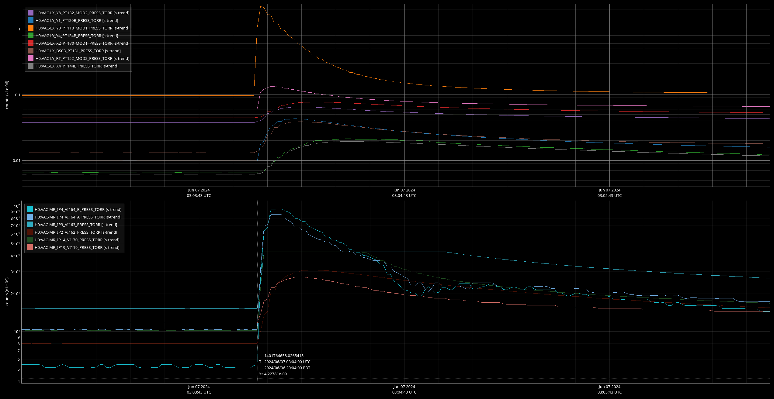
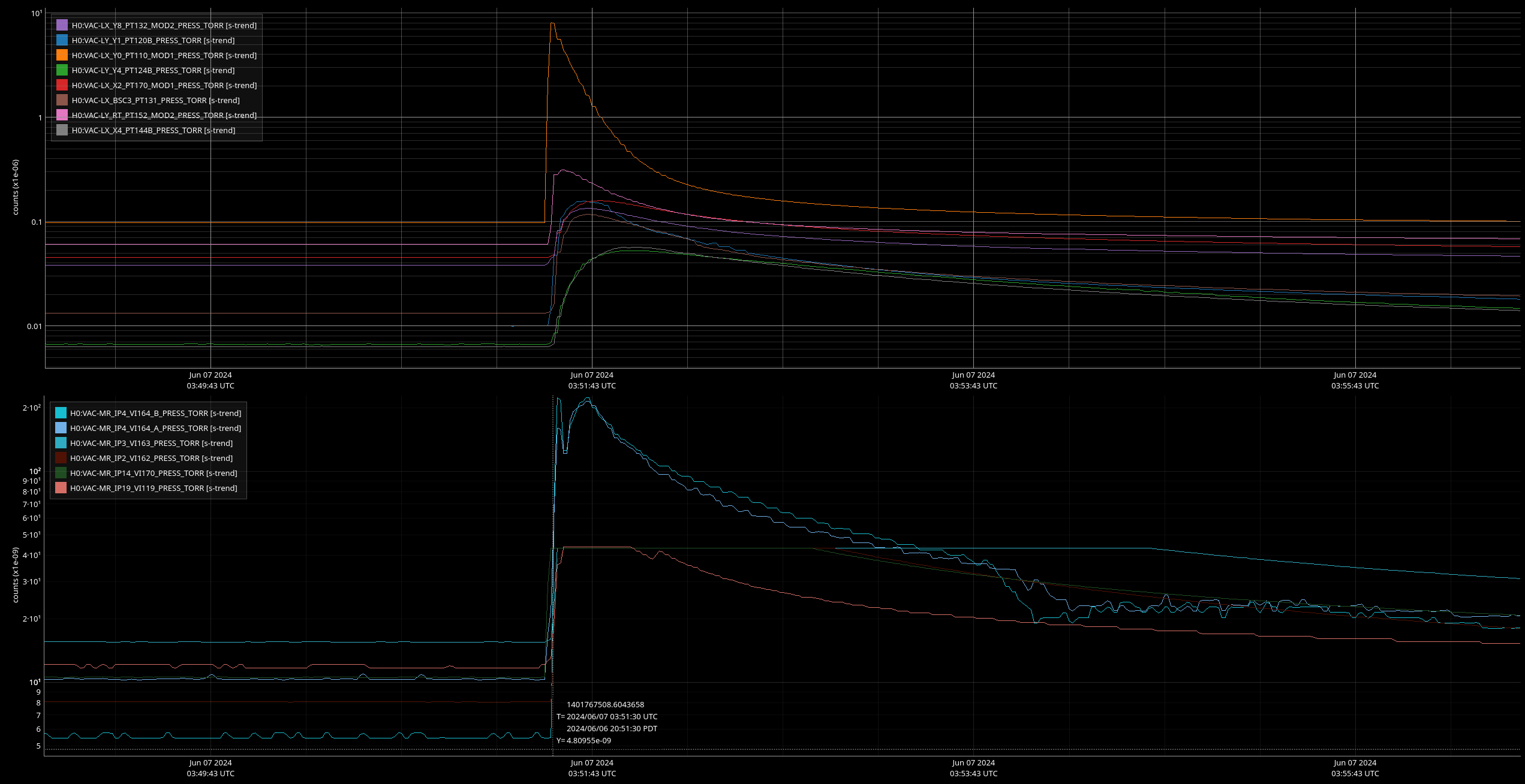
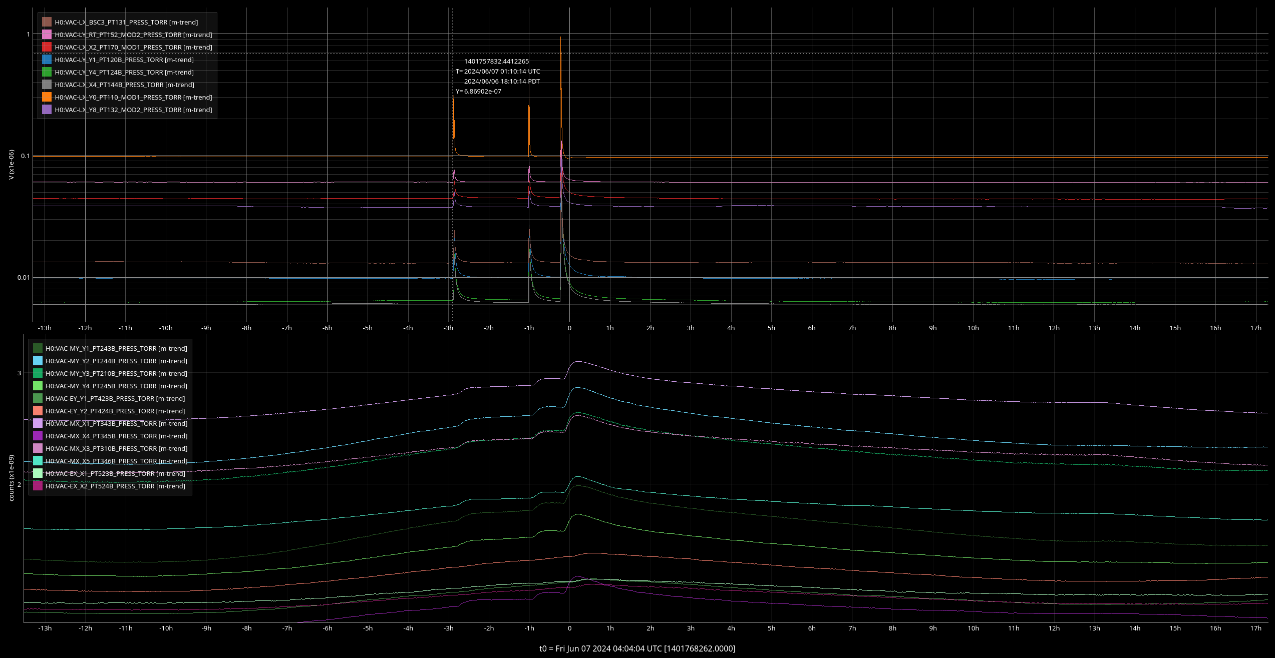
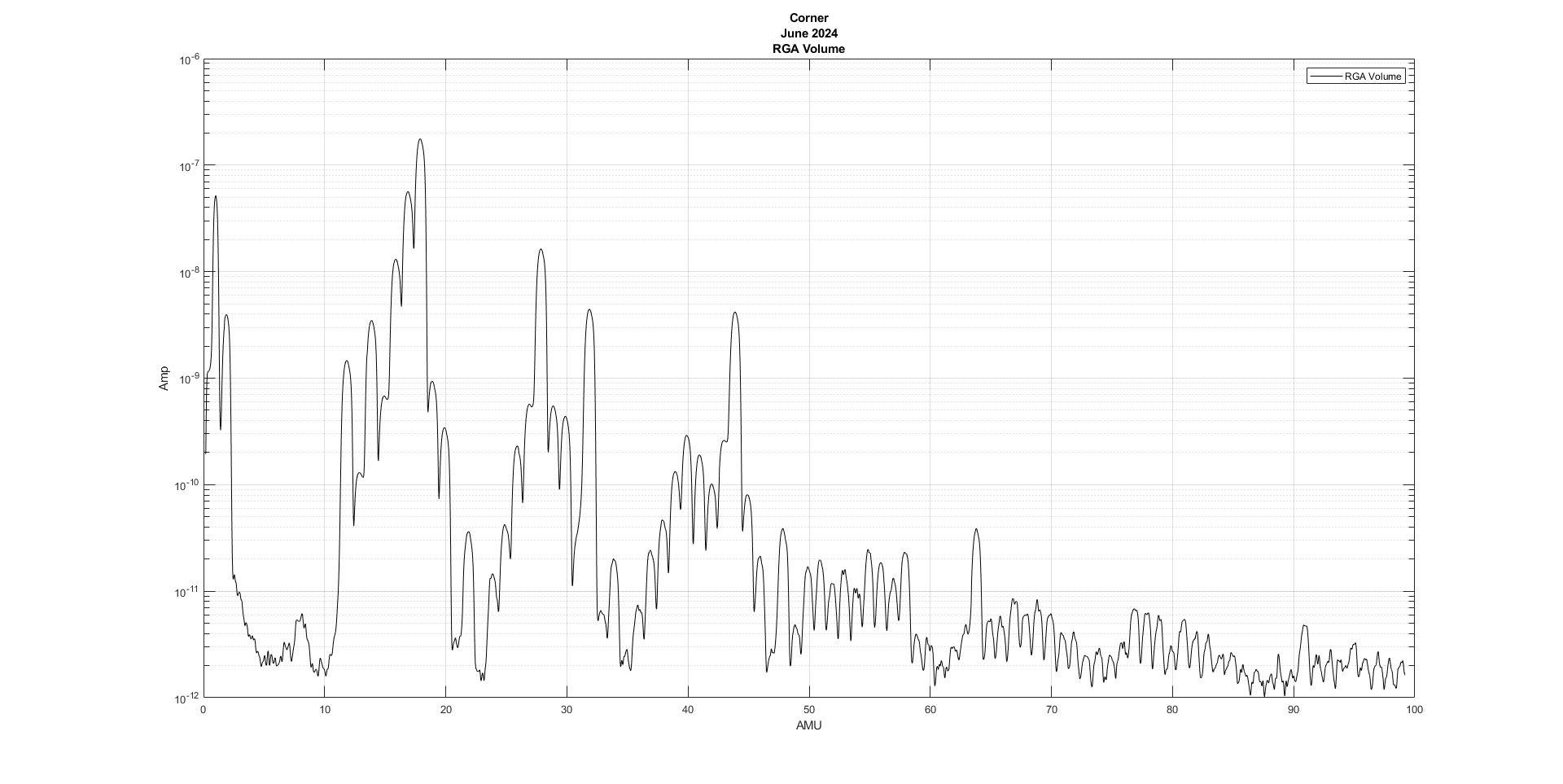
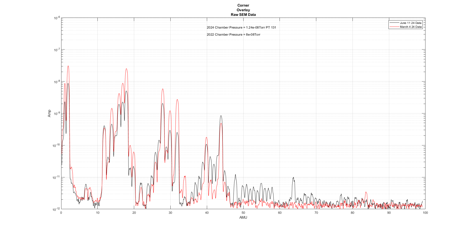
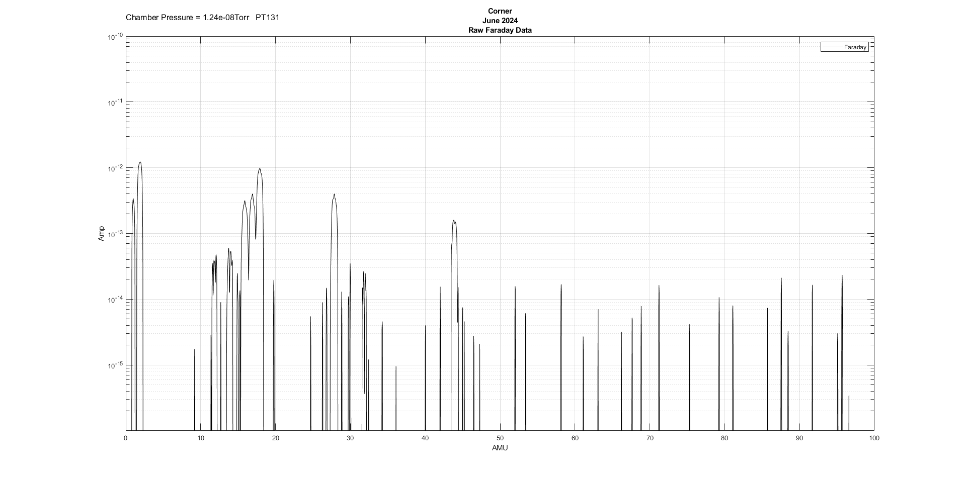
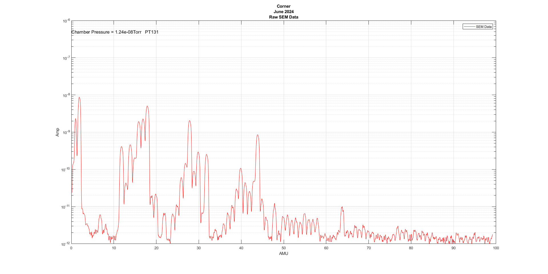
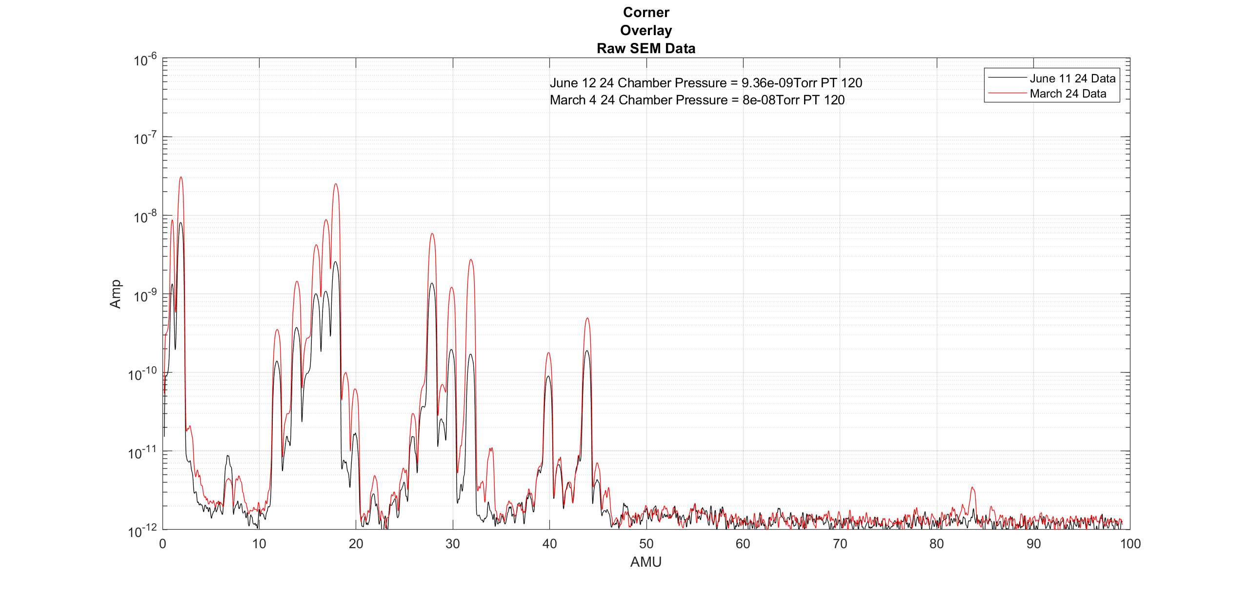
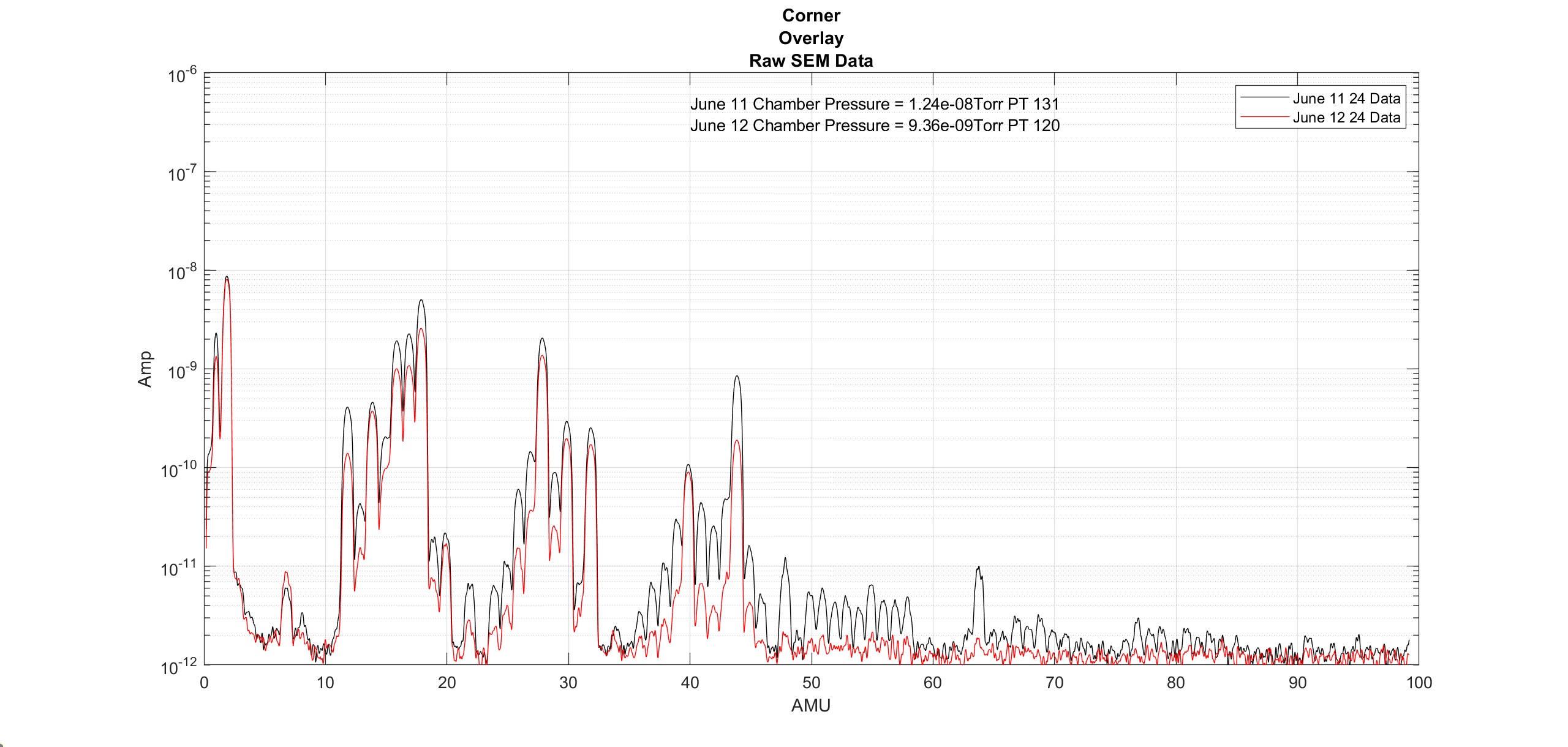
| 15:09 | VAC | Jordan | LVEA | n | Setup RGAs on output arm | 18:11 |
| 15:10 | FAC | Karen, Kim, Nelly | LVEA | n | Tech clean | 16:18 |
| 15:14 | VAC | Gerardo | LVEA | n | Input tube AIP work (climbing on tube) | 16:31 |
| 15:15 | CDS | Erik | EX | n | ADC install | 15:53 |
| 15:19 | SAF | Oli | LVEA | n | Transition LVEA to laser SAFE | 15:53 |
| 15:21 | IAS | Jason, TJ O., Tyler, Ryan C | LVEA | yes | FARO work | 21:58 |
| 15:28 | Film | Mike, Richard, film crew | LVEA | YES | Filming | 22:47 |
| 15:32 | OMC | Jeff | LVEA - HAM6 | - | DCPD electronics testing | 19:39 |
| 15:51 | CDS | Erik, Fil | EX | n | Add ADC to h1iscex | 16:18 |
| 15:52 | DAQ | Dave | remote | n | DAQ RESTART for EX work | 16:21 |
| 15:52 | VAC | Janos, Isaiah | EX, LVEA | n | Pump testing | 17:34 |
| 15:54 | FAC | Ken | LVEA | n | Cable tray install on FC tube area | 18:27 |
| 16:08 | FAC | Chris | LVEA, FCES, EX, EY | n | FAMIS tasks | 18:00 |
| 16:10 | PEM | Sheila | LVEA | n | Magnetometer move | 16:10 |
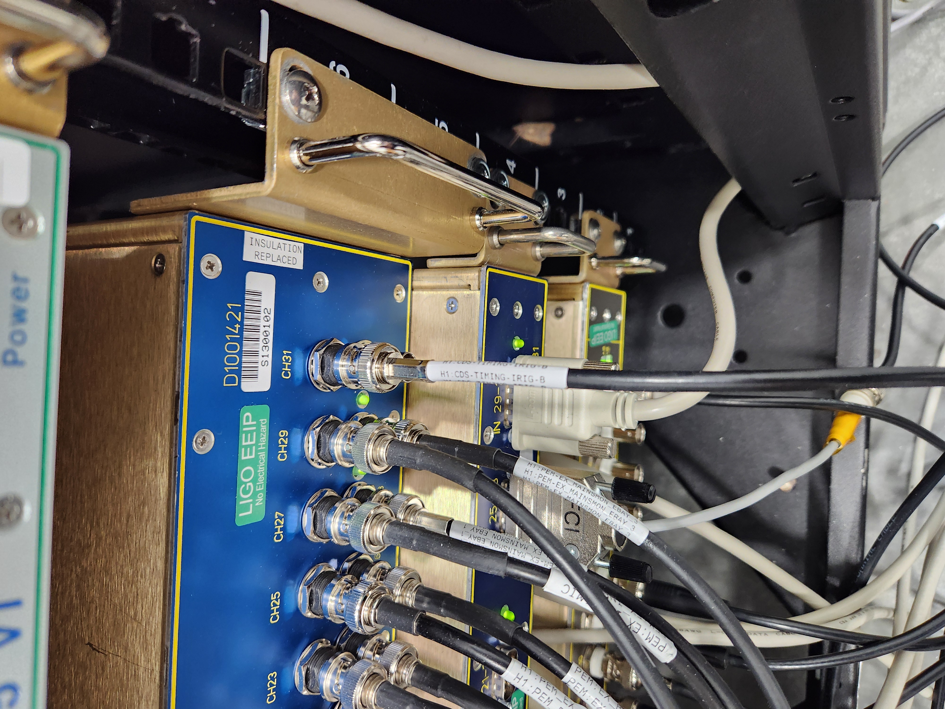
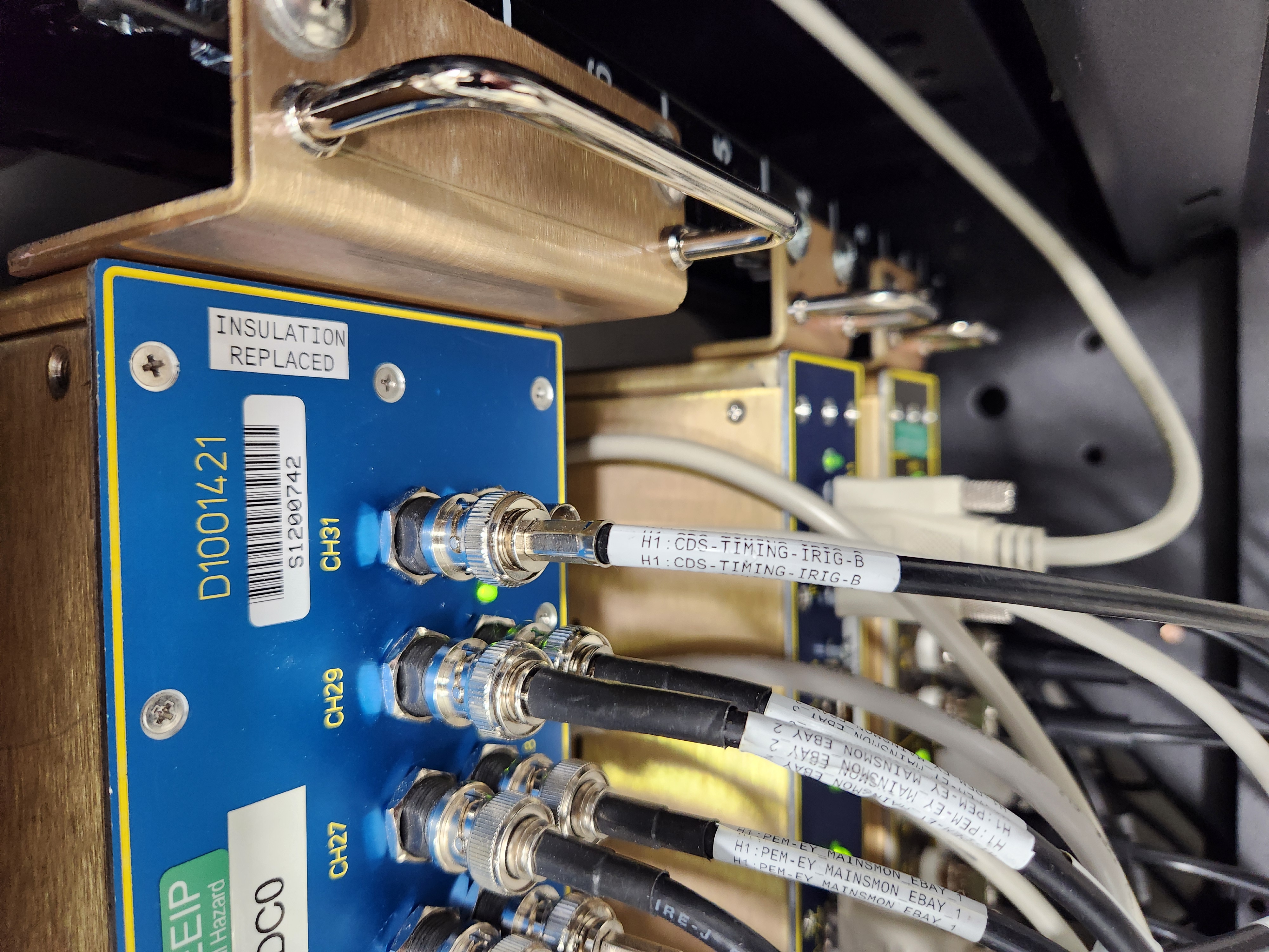
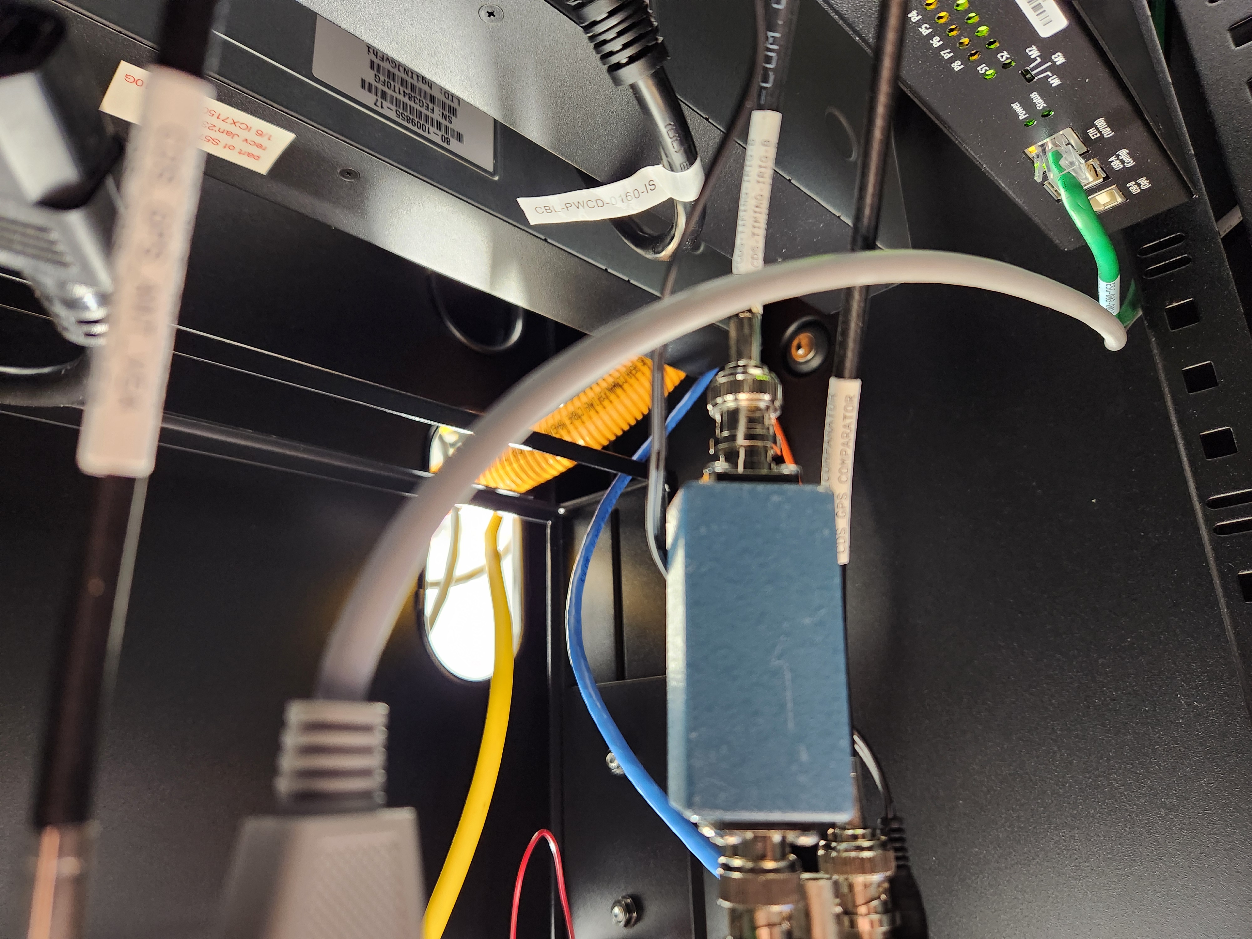
| 16:21 | CDS | Fil, Marc | EY | n | Reconnect IRIGb, install PEM AA chassis but not plug in | 17:01 |
| 16:32 | VAC | Norco | EY | n | CP7 fill | 19:24 |
| 16:36 | VAC | Travis | MX, EX | n | Turbo testing | 19:24 |
| 17:11 | SEI | Jim | Ends | n | Look for regulator | 18:18 |
| 17:19 | FAC | Kim | EX | n | Tech clean | 18:18 |
| 17:20 | FAC | Karen, Nelly | EY | n | Tech clean | 18:11 |
| 17:44 | PCAL | Francisco | EX | LOCAL | PCAL meas. | 19:34 |
| 17:58 | SAF | HAZARD | EX | YES | EX is Laser HAZARD | 19:34 |
| 18:11 | VAC | Norco | CS | n | CP2 fill | 20:04 |
| 18:14 | VAC | Gerardo, Jordan, Fil, Marc | LVEA | n | Pull cable from Y BM to mech room | 18:57 |
| 19:00 | VAC | Janos, Isaiah | EX | yes | Pump testing | 20:28 |
| 19:09 | CDS | Fil | High bay | n | Clearing out for genie lift to fit | 19:36 |
| 19:21 | SQZ | Kar Meng | Opt Lab | local | SHG work | 20:05 |
| 19:46 | CDS | Jonathan, Jamie, Dan | Remote | n | GDS/DMT restarts | 20:59 |
| 21:48 | VAC | Gerardo | LVEA | yes | Looking at VPs | 22:12 |
| 21:54 | VAC | Janos | EX | n | AIP check | 22:12 |
| 23:13 | Film | Film crew | FCTE | n | Filming the FCTE | 00:13 |