Andrei, Naoki, Sheila
Following the research of aLOG 78125 and aLOG 78262, we aimed to quantify the value of backscattering from the ZM2 and ZM5. We performed backscattering measurements under the assumption that modulation of the optical path between scatterer and interferometer would introduce additional noise in the DCPD spectrum [1-4].
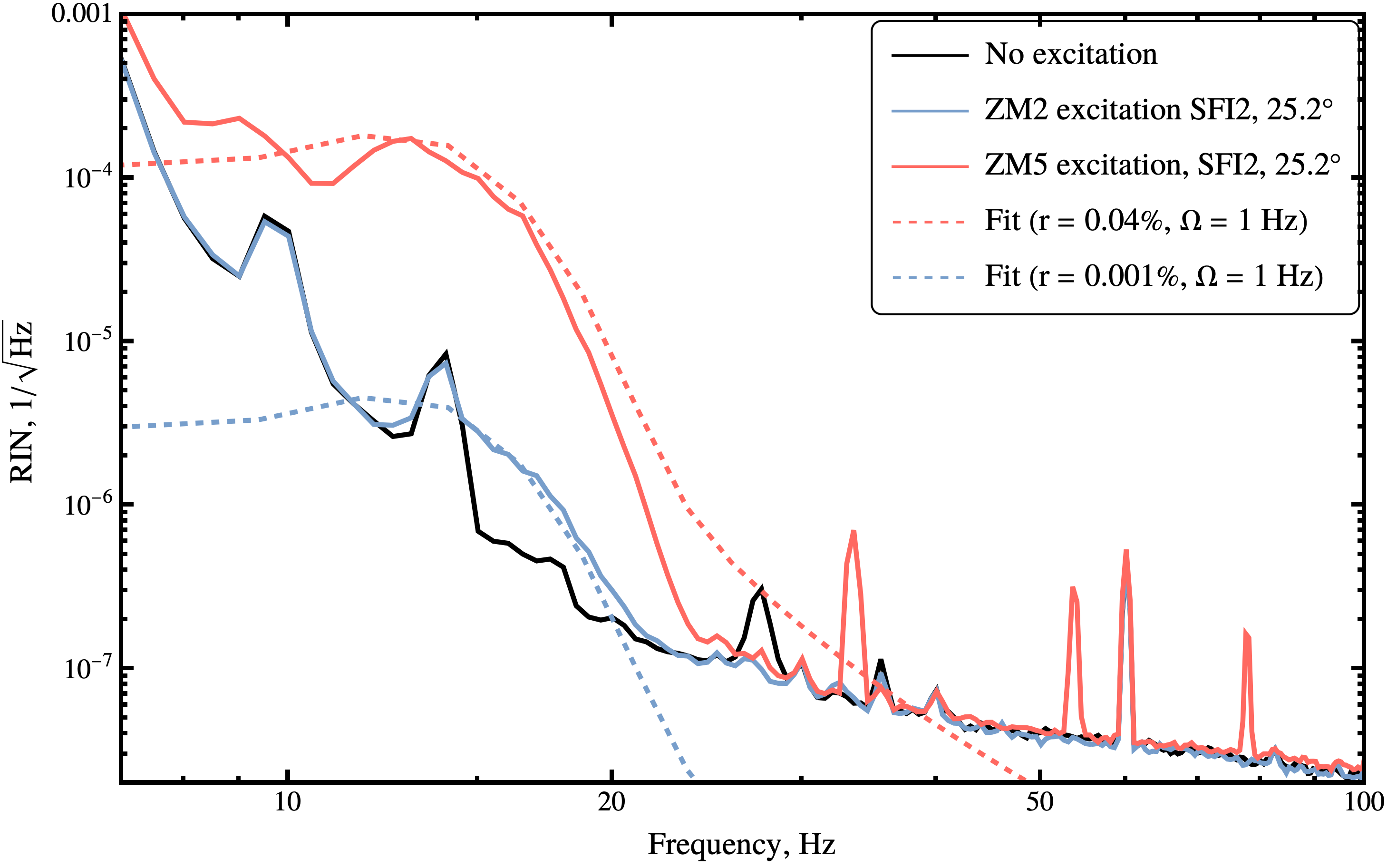
We used data from the H1:OMC-DCPD_SUM_OUT_DQ channel (calibrated to mA of photocurrent) for the times of aLOG 78125. We've then calculated RIN with correction for the DARM control loop. Using Eq. 25 from [1], we performed manual fit. Although we couldn’t perfectly fit within the range from 15 Hz to 21 Hz (probably because of the chosen Welch's transform parameters), we were still able to obtain meaningful results for the backscattering coefficients (see Fig. Backscattering_meas.png). The resulting coefficients are below:
rZM5 ≈ 4 x 10⁻⁴
rZM2 ≈ 0.1 x 10⁻⁴
Also note, that the amplitude of the excitation used for fit is several times larger than that we've measured from the H1:SUS-ZM#_M1_DAMP_L_INMON channel (1.2 μm unstead of 0.4 μm).
Code that was used for this calculation is attached to this report. OM1_fringewrapping_test.m (Sheila's code) was used to calculate RIN, main.nb was used for manual fit and plotting.
[1] Martynov, D. V., Hall, E. D., Abbott, B. P., Abbott, R., Abbott, T. D., Adams, C., ... & McIver, J. (2016). The sensitivity of the Advanced LIGO detectors at the beginning of gravitational wave astronomy. Physical Review D, 93(11), 112004.
[2] Ottaway, D. J., Fritschel, P., & Waldman, S. J. (2012). Impact of upconverted scattered light on advanced interferometric gravitational wave detectors. Optics express, 20(8), 8329-8336.
[3] Nguyen, P., Schofield, R. M. S., Effler, A., Austin, C., Adya, V., Ball, M., ... & Moreno, G. (2021). Environmental noise in advanced LIGO detectors. Classical and Quantum Gravity, 38(14), 145001.
[4] Fricke, T. T. (2011). Homodyne detection for laser-interferometric gravitational wave detectors. Louisiana State University and Agricultural & Mechanical College.