Sheila, Jennie W
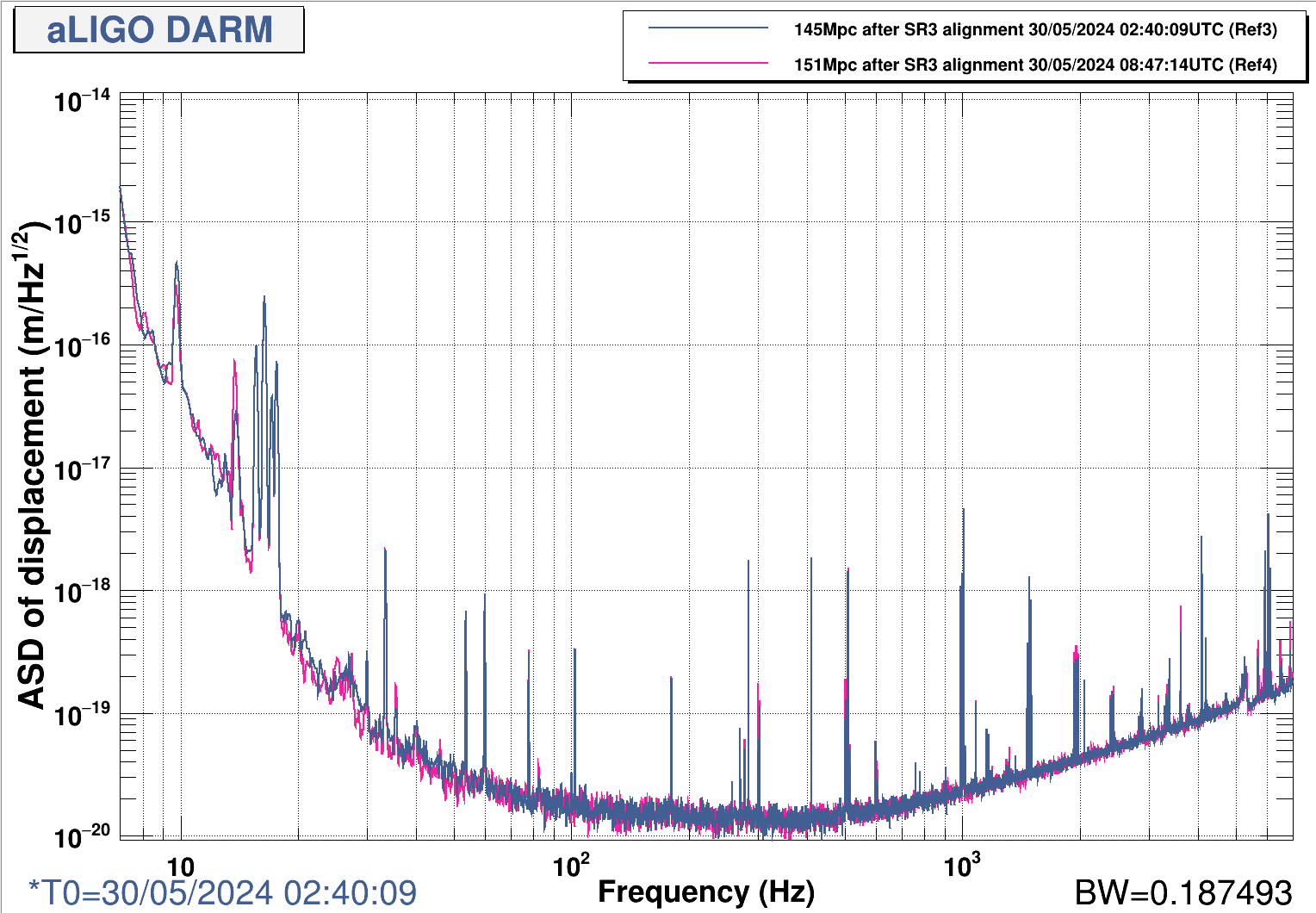
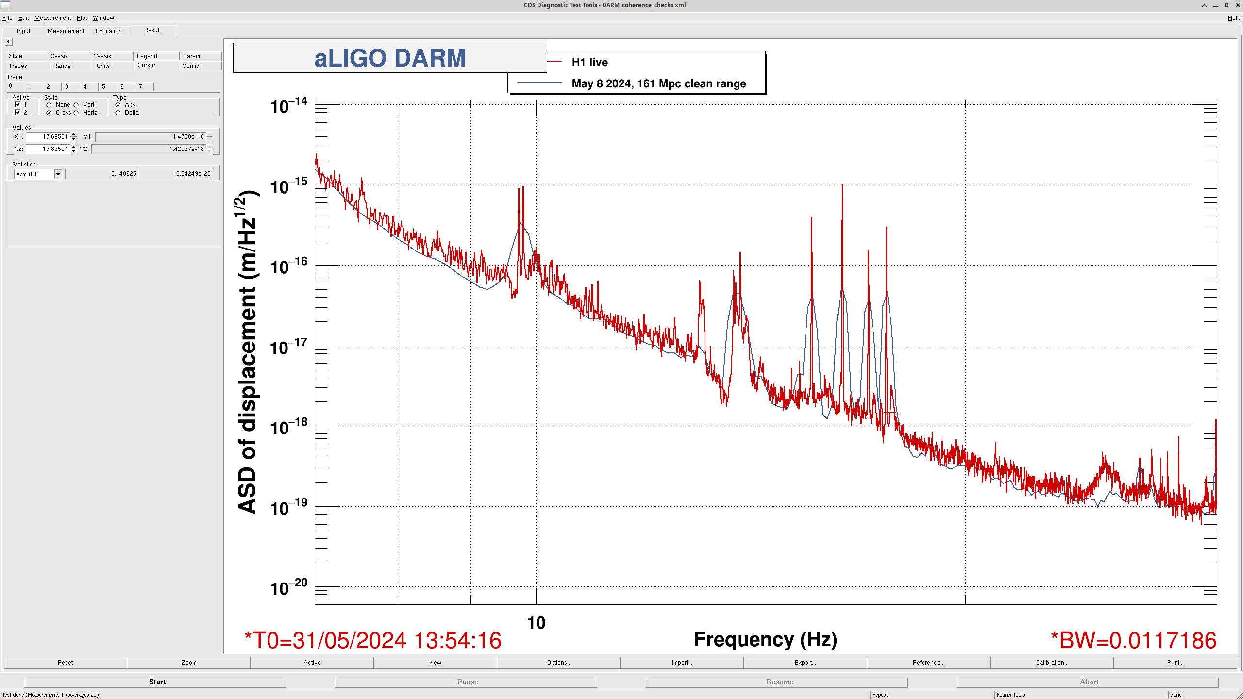
Sheila and Annamaria realised we have a noise bump around 17.75 Hz and hypothesised it could be the bounce mode of the beamsplitter which we have not retuned since adding the BRD (bounce-roll mode dampers) on the beamsplitter.
The LSC-MICH loop feeds back to the beamsplitter.
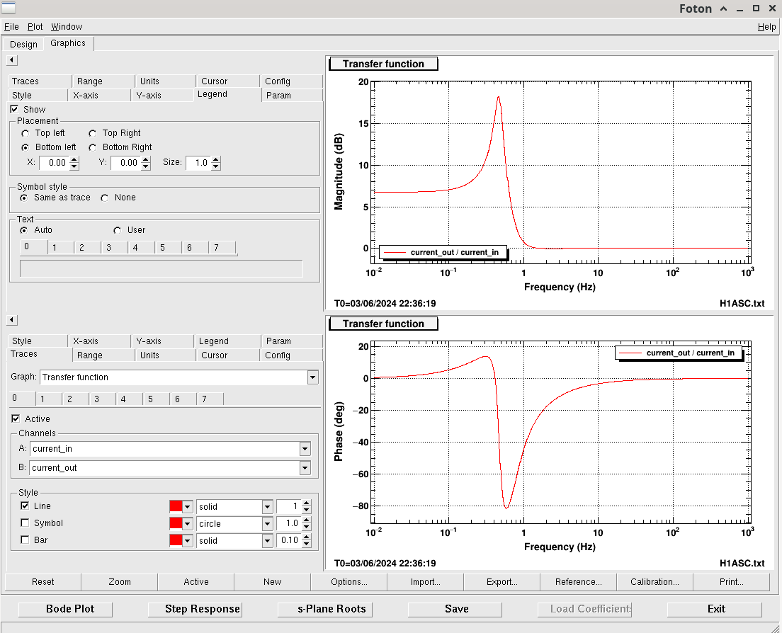
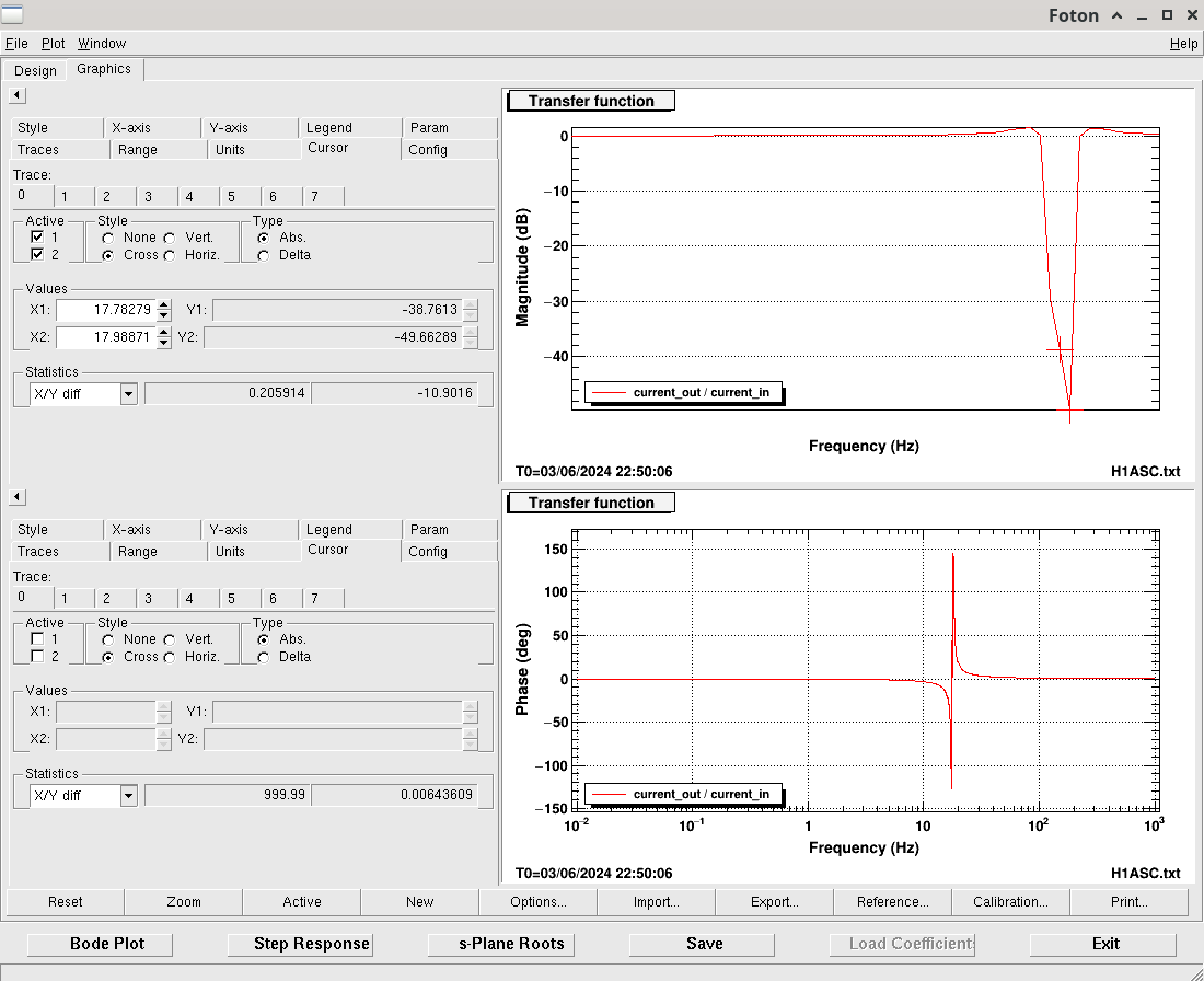
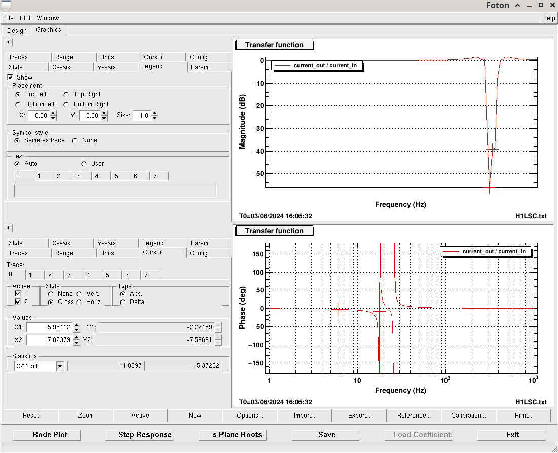
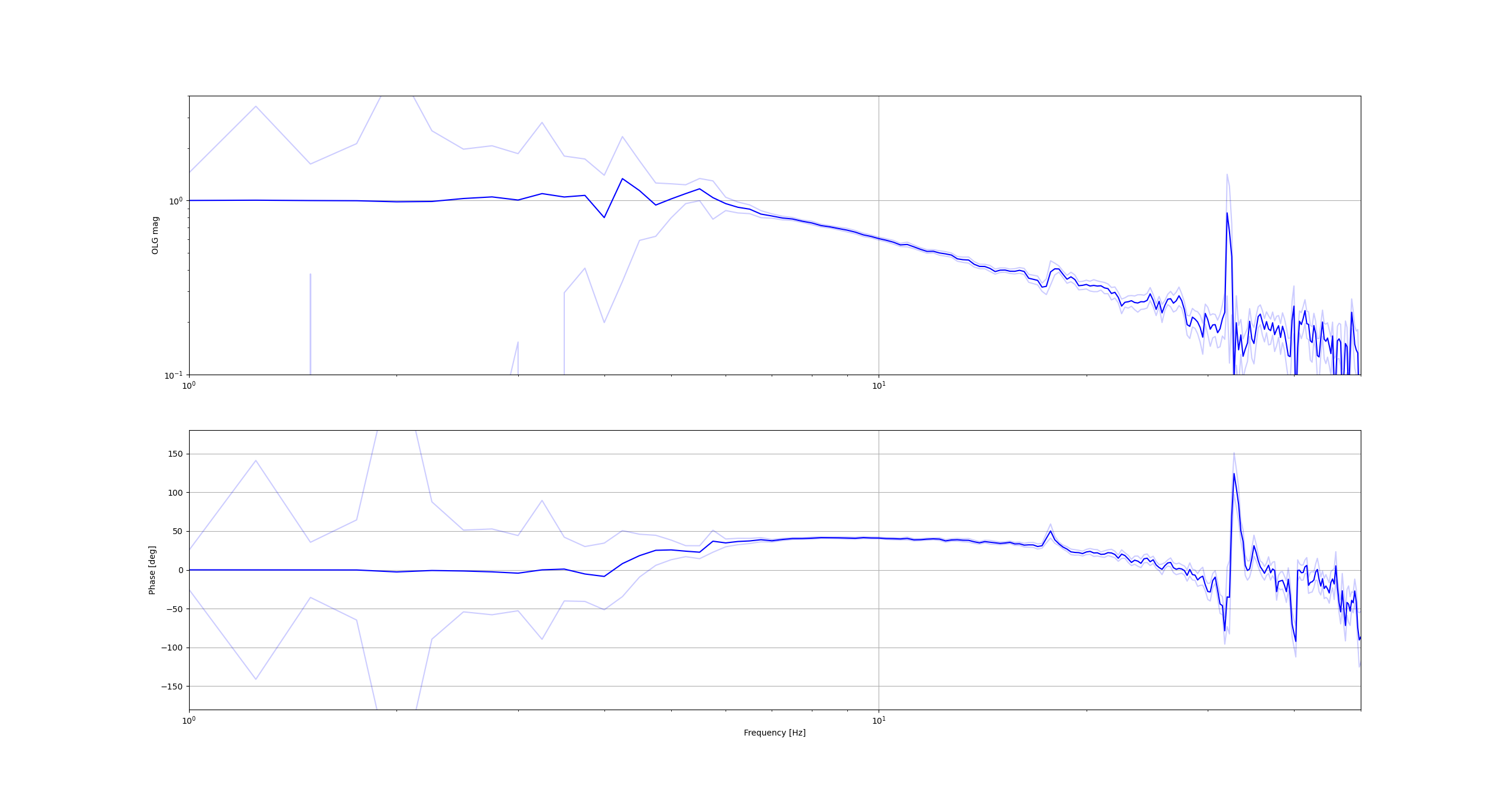
The measurement of the MICH loop is shown in this plot where it has a UGP 5.87Hz and phase margin of 35.5 degrees.
Code was adapted from Sheila's in this alog and is saved in /ligo/home/jennifer.wright/Documents/Filter_Design/plot_noise_OLG.py - although we are not sure if uncertainty estimates are accurate and the measurement is low coherence below 6Hz (near the UGP).
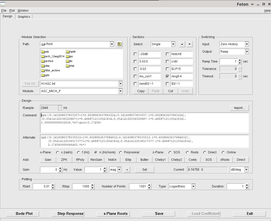
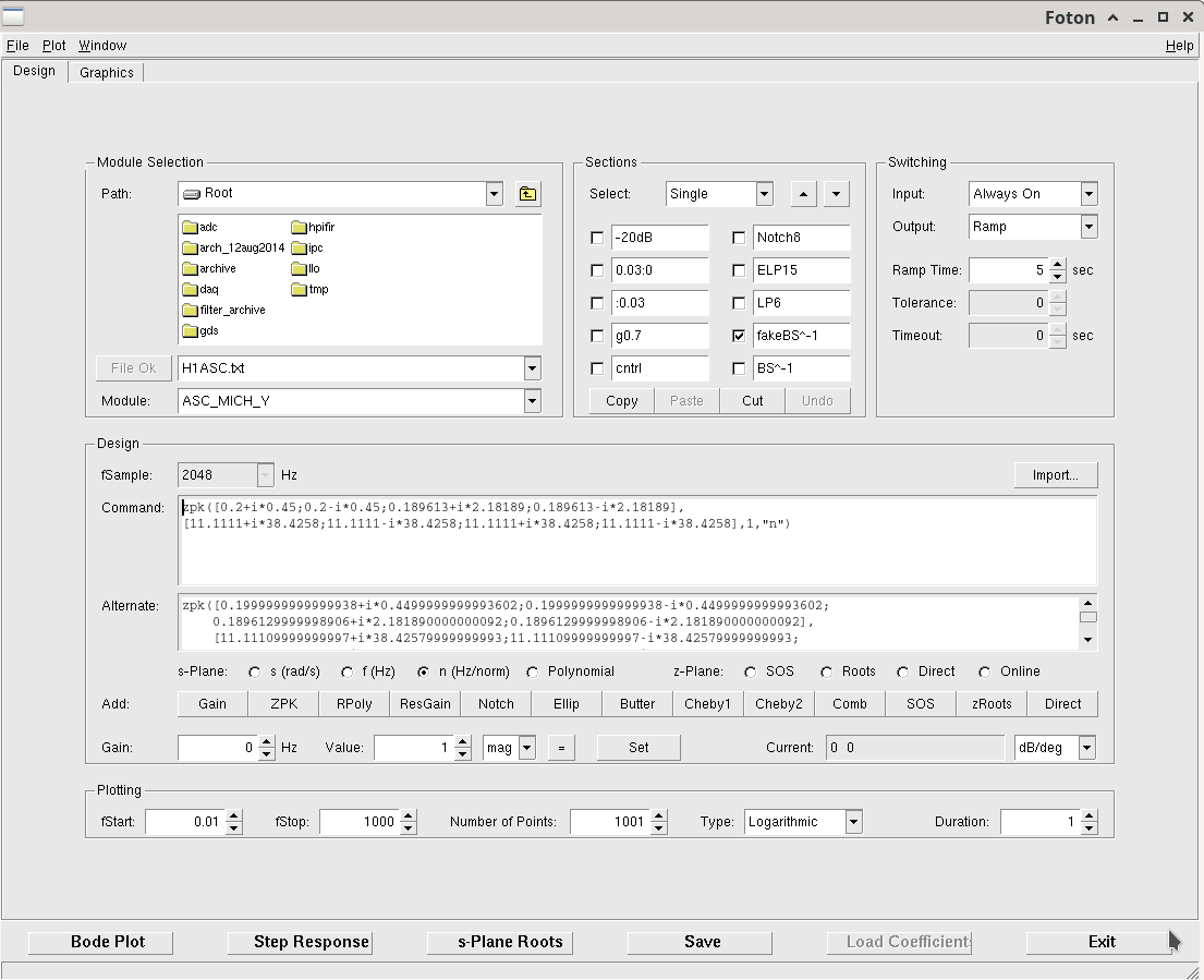
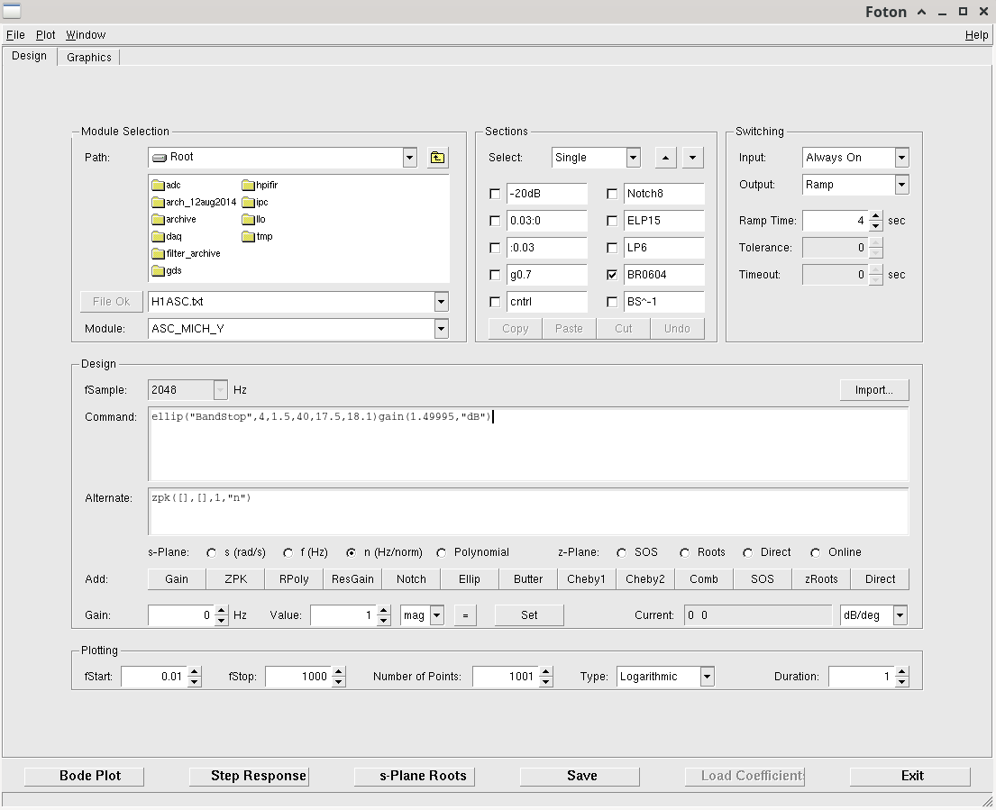
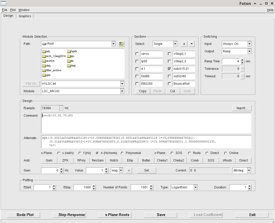
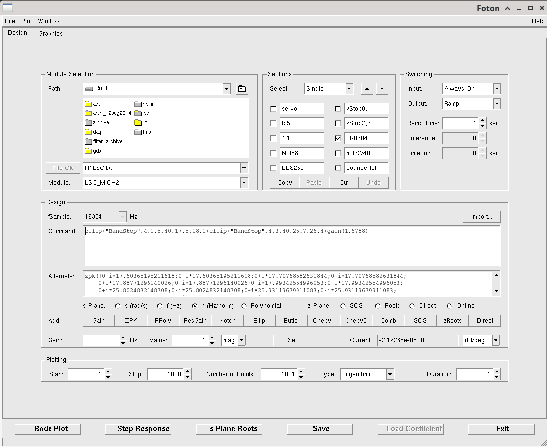
Sheila looked through the guardian and realised that we don't use FM8 in locking so we will overwrite the 15Hz notch here. Therte is an existing BRD bandpass in FM10 with this shape, which is used in locking, we don't want to overwrite this at the moment but we might once we test the new filter.
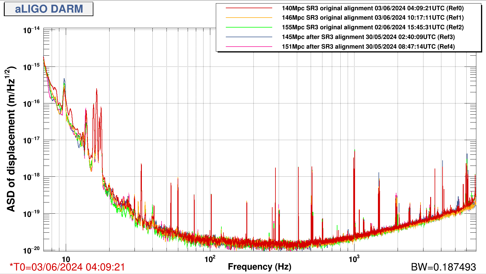
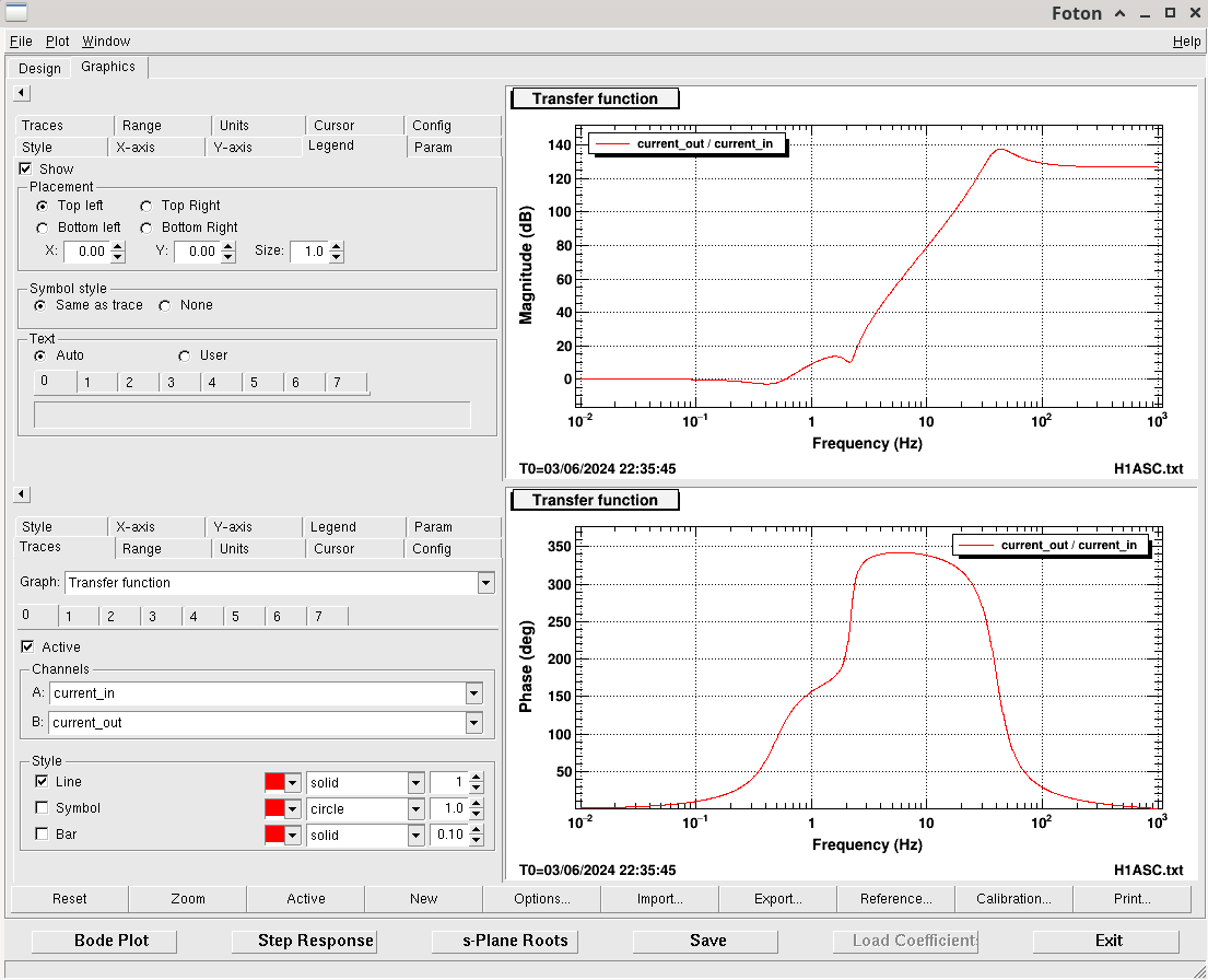
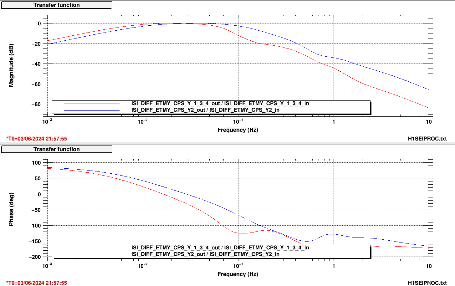
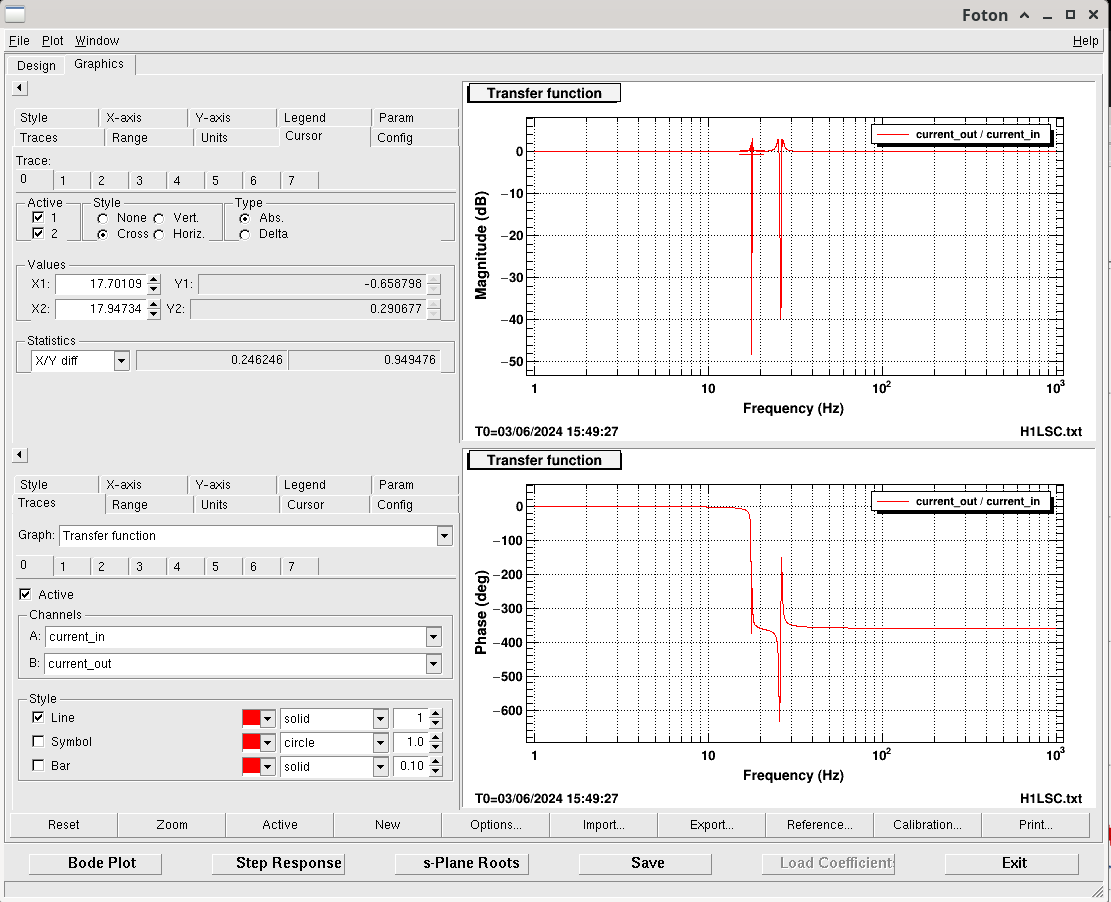
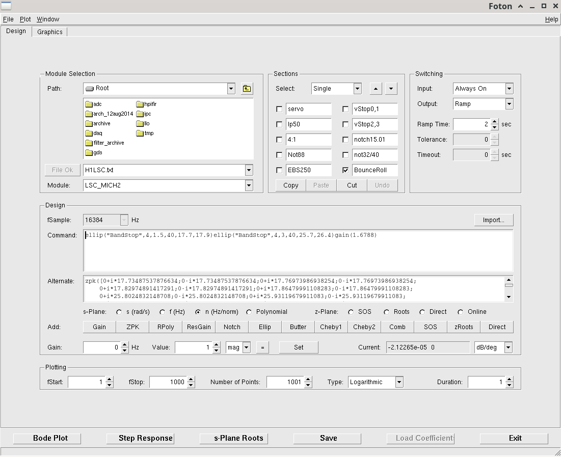
I copied over the FM10 filter to FM8 and then made it a bit wider to match the width of the bounce mode in the DARM spectrum found in this measurement from the 8th May.
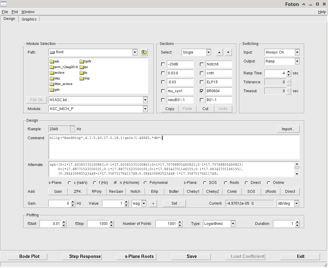
The new filter is here and has this shape. We made it always on with a ramp of 4s and it is called BR0604.
I reloaded the LSC model coefficients (twice because I forgot to change the filter name the first time).
We will not test it till our next commissioning period.


Back to Observing at 05:19UTC